Week 10
Mechanical Design
Machine Design
Brief Overview
This assignment is about documenting what we as a group learned in Mechanical Design and Machine Design week that includes what all we did as a group. The tasks were divided as per the processes and yet work was completed through a collaborative and concurrent approach. This documentation includes our concept, brainstorming and processes (work break-down) we followed in designing and constructing our machine in brief.
Heroshot for this Week
.jpeg) |
.jpeg) |
 |
.jpeg) |
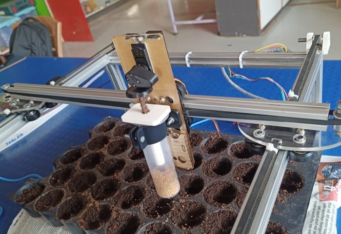
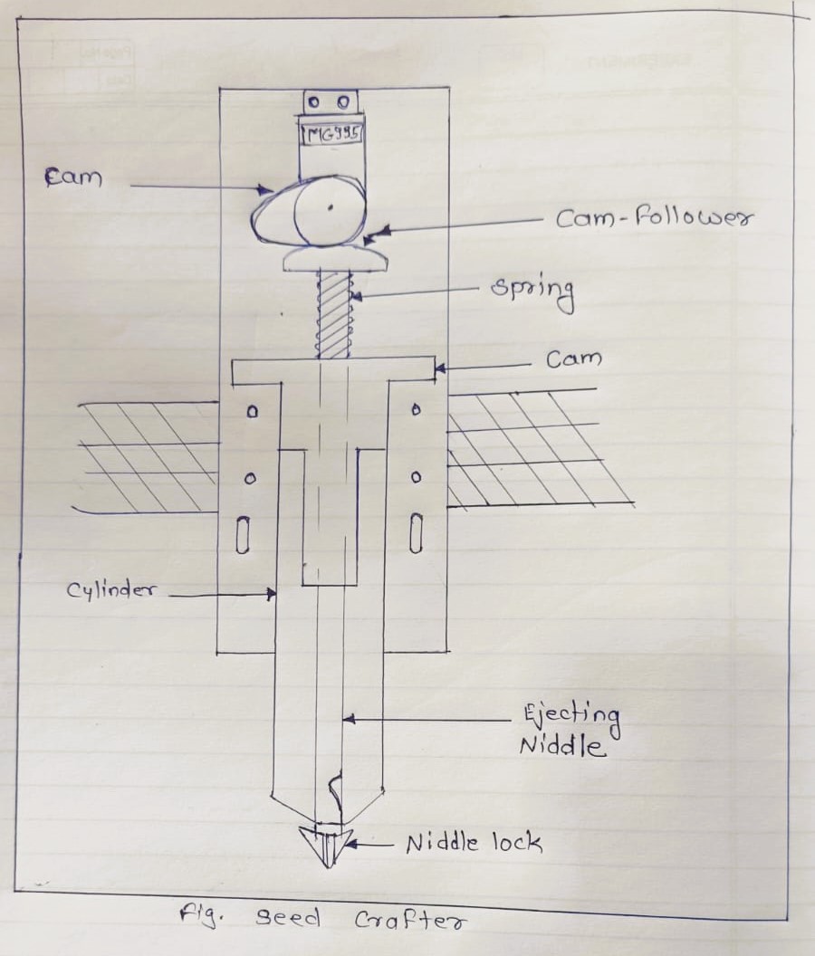
Seed Crafter
Machine Video Presentation:-
You can refer our Group Page here
Introduction:-
Roles and Responsiblities
In this journey we had many individual contributor also who helped us a lot including our intructor, colleagues and other co-working person in Vigyan Ashram
Inspiration :-
 |
 |
So this inspires us to make a machine which could do this automatically do this without human intervention.
Sketching
So we start sketching and collecting ideas and put on a piece of paper to final a sketch
CAD Modelling
We have decided to make basic gantry, and XY mechanism to navigate the machine at particular geaometric points.
We have refered some pre- designed part form GRABCAD, to assemble our machine.
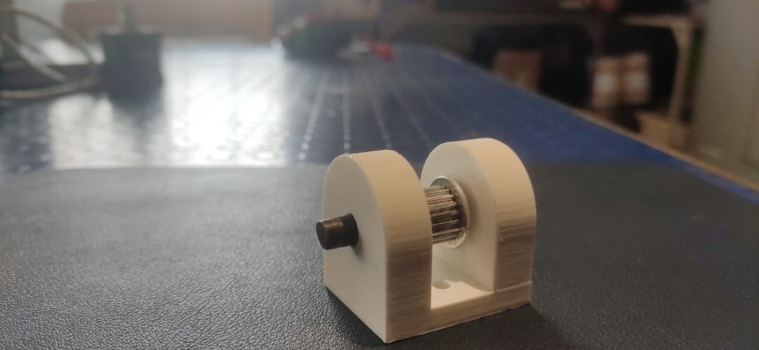
We have also made our own part for pulley holder.
.jpeg)
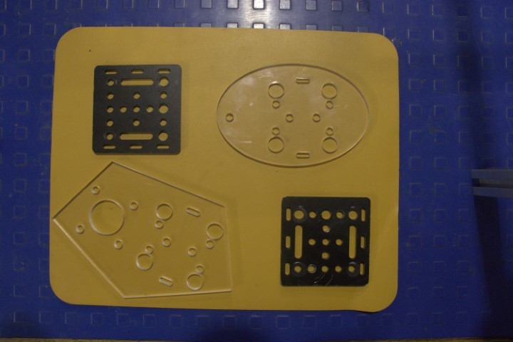
We have also designed and laser cut a plate to mount the stepper motor and attached the mounting plate to the gantry plate.
.jpeg)
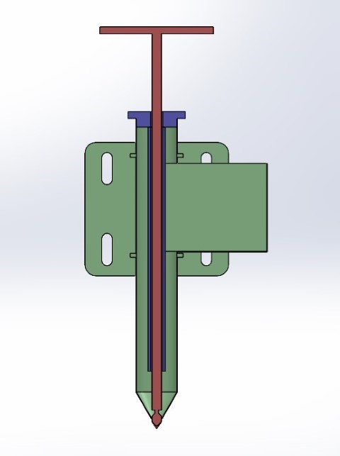
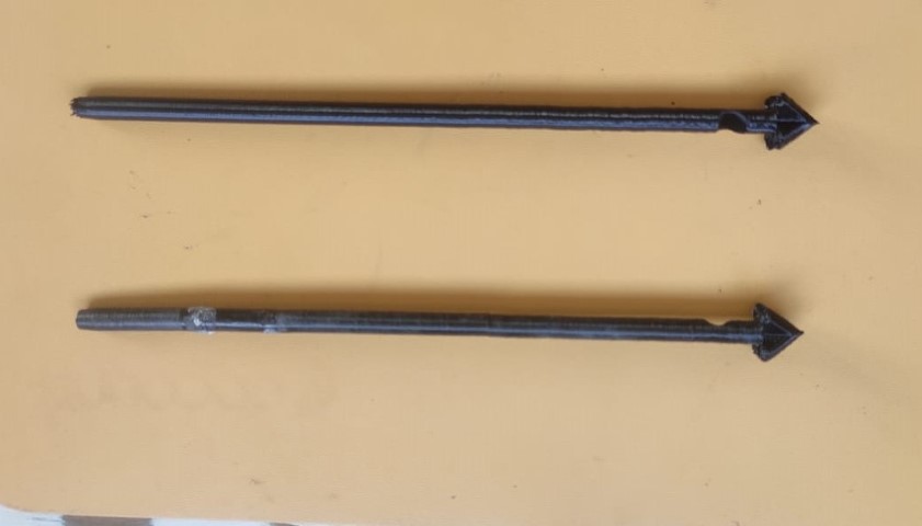
The most important part in the Machine is the end efector, so we have designed a integrated, extrude designed for drop seeds
 |
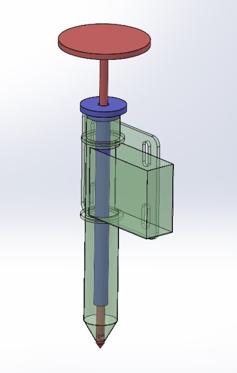 |
 |
.jpeg)
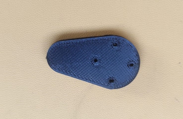
Similarly we have desihgned a part to hold our end effector with the gantry on Y axis.
.jpeg)
Parts and Components Used:-
Mechanical Components
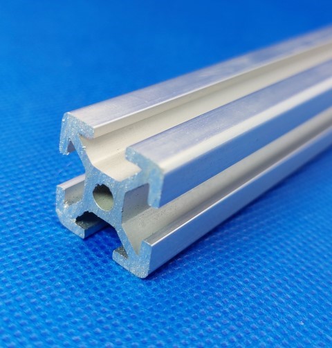
1) Aluminium Extrusion Channels
Aluminium extrusion channels serve various purposes in framing, creating reveals, and protecting millwork edges. They enhance surfaces with ease of maintenance, cleaning, and polishing, making them ideal for diverse design projects.
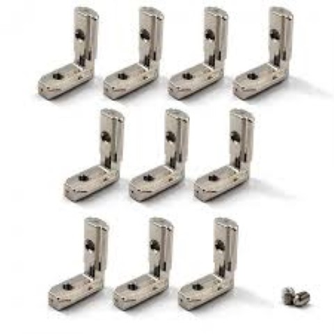
2) Extrusion V Slots Joint
The L-shaped hidden corner bracket facilitates right-angle connections between aluminum profiles. Inserting the bracket ends into profile grooves and tightening set screws securely fixes the profiles. Widely used in industrial aluminum frame structures, 3D printers, CNC routers, laser engravers, and robotics projects.
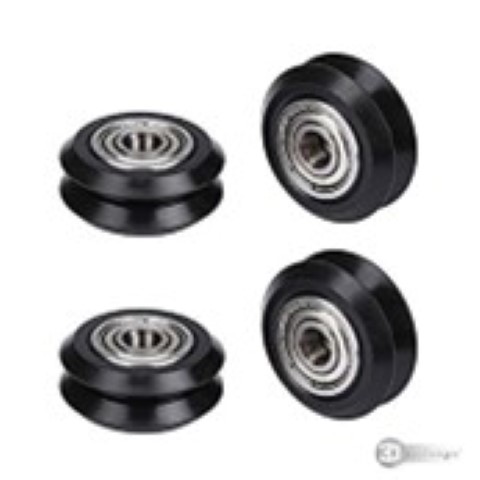
3) Bearing Wheels
These spindle bearings offer a unique structure with large load capacity, high smoothness, reliability, and performance. Equipped with special anti-backlash gear pulleys, suitable for various printers, advertising copiers, printing machines, and industrial applications.
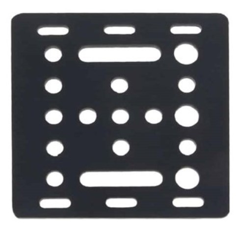
4) V Slot Gantry Plate
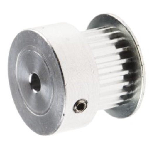
5) Aluminium Pulley
The GT2 Aluminium Pulley features 40 teeth, a 5mm bore, and a 6mm width. Constructed with high-quality aluminum, it offers strength, durability, and compatibility with GT2 6mm wide timing belts. Two set screws ensure firm attachment to a 5mm diameter shaft.
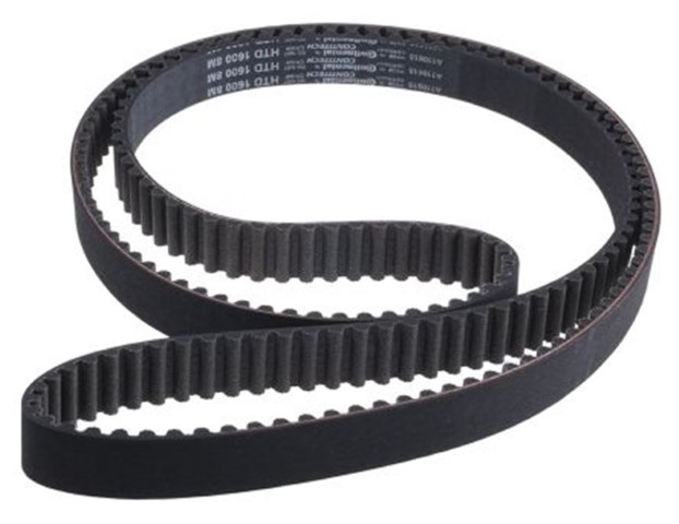
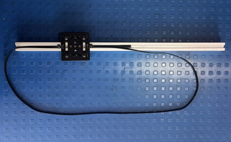
6) Timing Belt
The precision 10M GT2 Width 6mm Black Open Timing Belt is made from NEOPRENE Synthetic Rubber reinforced with fiberglass cords, providing superior strength. Suitable for various 3D printers and industrial applications.
Electronics
Arduino Uno
The Arduino Uno is an open-source microcontroller board based on the Microchip ATmega328P. Developed by Arduino.cc, it offers sets of digital and analog input/output pins for interfacing with various circuits and expansion boards.

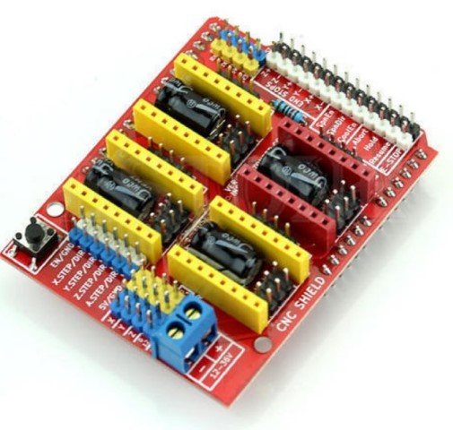
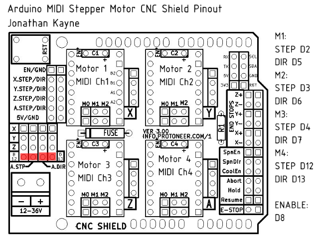
CNC Shield
The CNC Shield V3.0 enables the construction of engraving machines, 3D printers, and mini CNC devices using an Arduino. Designed as a shield, it plugs directly onto an Arduino, requiring no external connections. Equipped with slots for stepper motor drive modules, enabling easy setup and control.
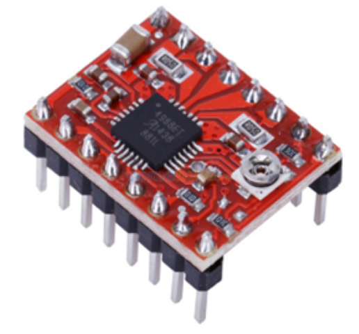
Motor Driver
The A4988 Module is a compact breakout board for Allegro's A4988 Stepper Motor Driver. Offering adjustable current limiting, over-temperature, and over-current protection, it provides precise control for stepper motors with a wide operating voltage range.
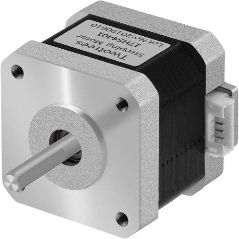
Nema 17 Stepper Motor
Known for precise position control, the NEMA17 4.8 kg-cm Stepper Motor offers 4.8 kg-cm of torque at 2.5A current per phase. Ideal for applications requiring excellent response to starting, stopping, and reversing pulses.
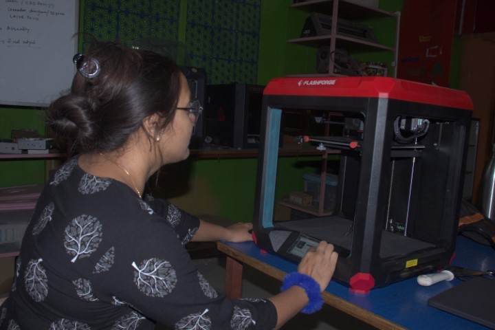
Fabrication
3D Printed Parts
We have printed and tested the 3D printed parts and assembled togheter to form a machine.

Laser Cutting Parts
We have laser cut the Mounting Plate on 6mm acrylic sheet.
Assembly Process
So we have now all the part togheter to start the assembly
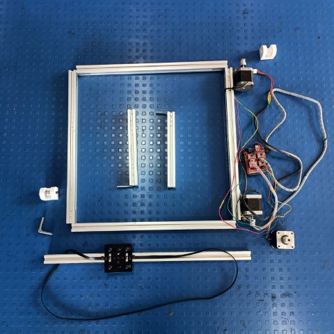
1) Chassis Fitting
Firsty we have assembled the individual part of machine toghether to assemble this individual part into machine, we had followed the Bottom-up approach.

.jpeg)
.jpeg)
.jpeg)
.jpeg)
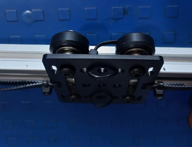
2) Gantry Plate Mounting
Mounted gantry plate with roller wheels for smooth X & Y axis motion, ensuring linear flow.
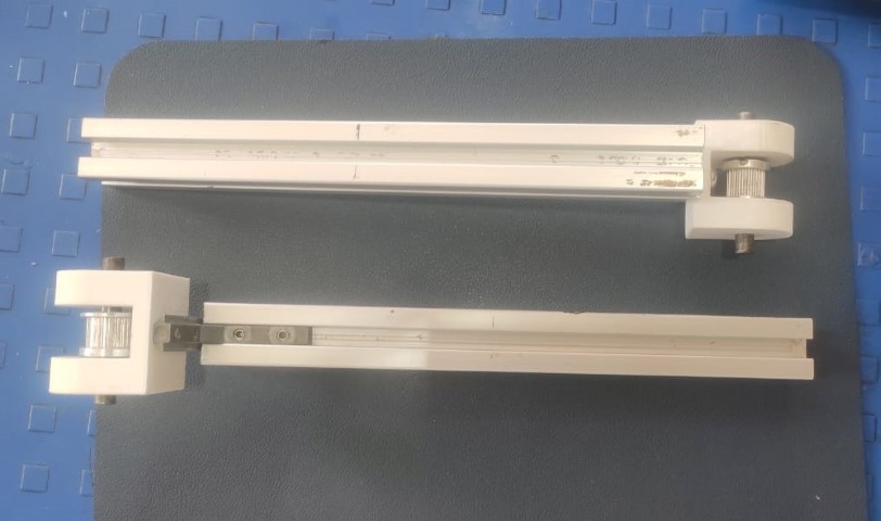
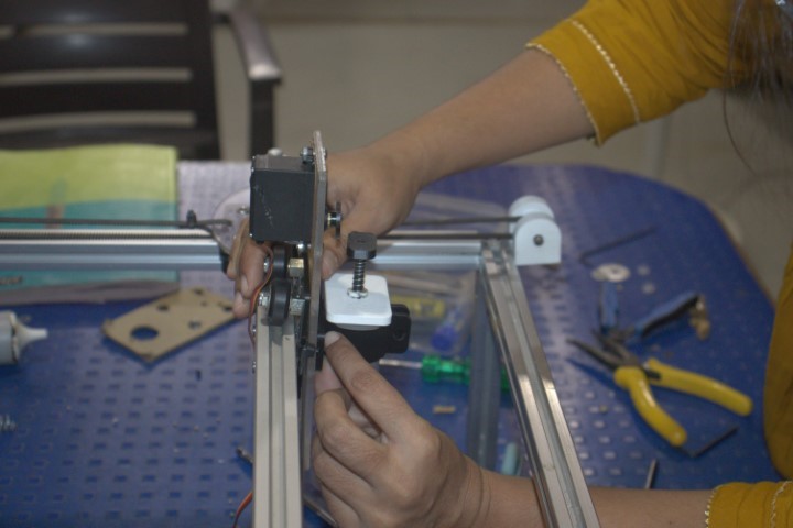
4) Timing Belt & Pulley Fitting
Utilized threaded pulleys and timing belts for motion transfer from motor to gantry plate.
6) Electronics Fitting
Completed all electronic connections and mounted components onto the machine.

.jpeg)
5) Electronic Component Testing
Completed all electronic connections and conducted testing.
.jpeg)
Individual Contribution:-
So as we were only 2 fabcademy students, we have to split the work and manage the project work between both of us, so as Prachi took the responsiblity of Design 3D part and I have work on Electronics connection and Coding.
This is how I automated the work by using GRBL and Universal Gcode sender.
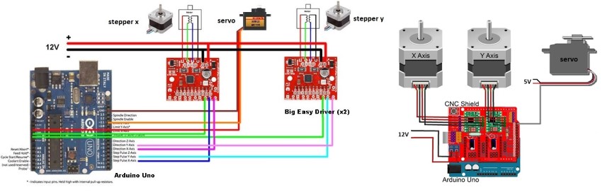
7) GRBL with Arduino UNO
What is GRBL?
GRBL is an open source software or firmware which enables motion control for CNC machines. We can easily install the GRBL firmware to an Arduino and so we instantly get a low cost, high performance CNC controller. The GRBL uses G-code as input, and outputs motion control via the Arduino .

From the diagram we can see where the GRBL take place in the “big picture” of the working principle of a CNC machine. It’s a firmware that we need to install or upload to the Arduino so it can control the stepper motors of the CNC machine. In other words, the function of the GRBL firmware is to translate the G-code into motor movement.
How to Install GRBL:-
Firstly, to install or upload the GRBL to the Arduino we need the Arduino IDE.
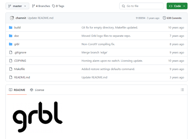
Then we can download the GRBL from github.com
Download it as .ZIP file and then follow these steps:-
- Open the grbl-master.zip file and extract the files
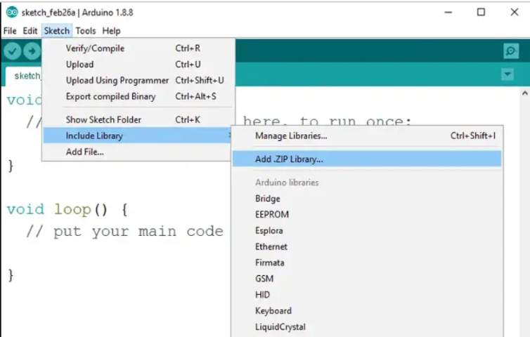
- Open the Arduino IDE, navigate to Sketch > Include Library > Add .ZIP Library…
- Add new library to Arduino IDE
- Navigate to the extracted folder “grbl-master”, in there select the “grbl” folder and click the open file. Now we have to GRBL as an Arduino Library.

How to install grbl on arduino
8) Gcode Testing with Universal Gcode

Universal Gcode Sender Tutorial
Grbl firmware is uploaded to Arduino Uno. Now we need software to convert our file into Gcode and calibrate our machine.
1. Download and install "Universal Gcode Uploader" software.
2. Open the software. You'll see options for machine connection, XY and Z controlling, console, and a visualizer.
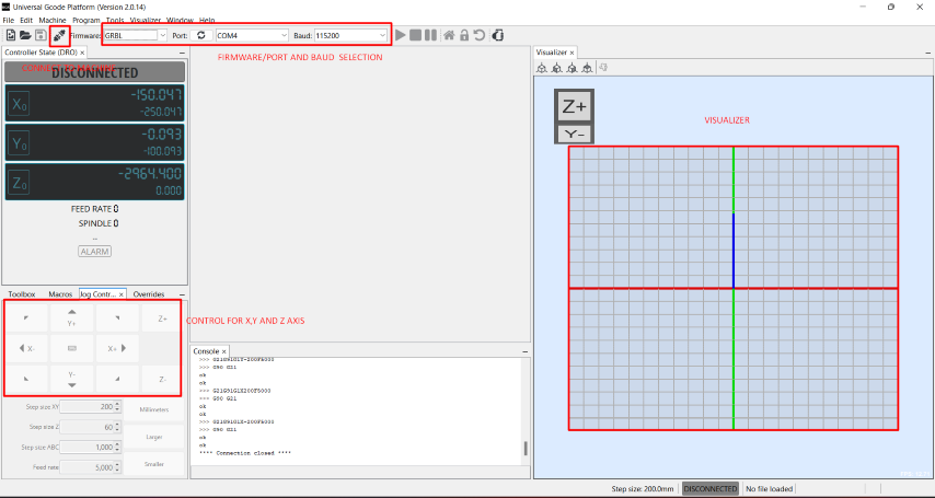
3. Select the Grbl firmware, Arduino port, and baud rate. Then click on the connect option to connect the machine.

4. Setup and calibrate the machine by selecting the "Machine" option and then "Setup Wizard."
5. In the setup wizard, confirm the connection between UGS and firmware, then click next.

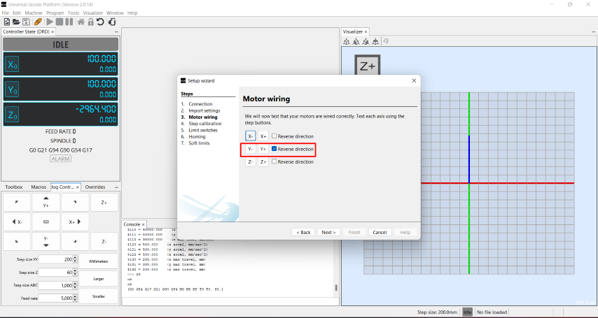
6. In the "motor wiring" option, correct any axis rotation direction if needed.
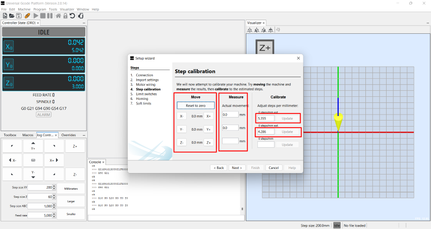
7. Calibrate the step by moving the axis in mm and checking the actual movement value in the machine. Enter the actual movement value, then update the calibration.
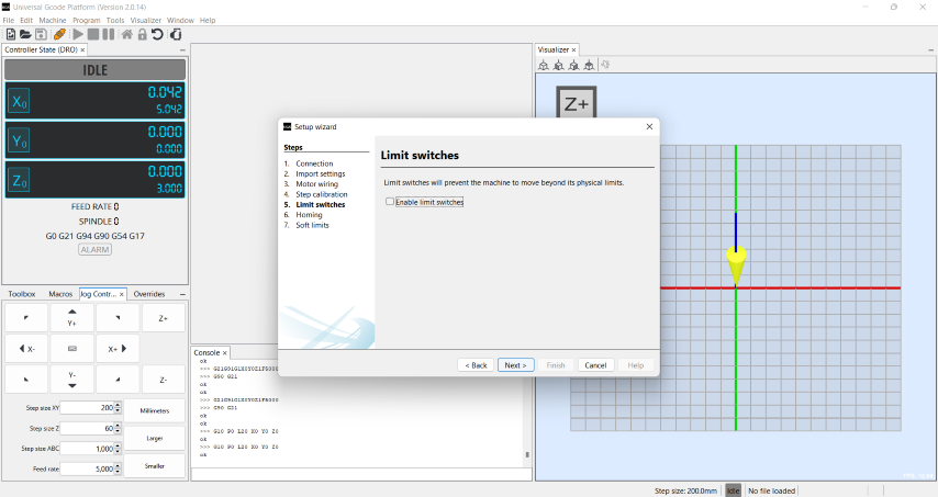
8. Enable limit switches if desired.
9. Use the console section to change axis speed, acceleration, and other parameters. Search for "$$" in the console, then copy and paste the values you want to change. Finally, click enter.
