Assignment 3: Computer Controlled Cutting
In Assignment 3, we explored the realm of computerized cutting processes. This portion of the course encompasses both individual and group tasks, each tailored to foster a comprehensive understanding of the subject matter. A fundamental aspect of this domain involves grasping the mechanics underlying machine cutting operations, particularly the relationship between power, velocity, and the resulting precision of the cut components. Within this context, we investigated the functionality of the vinyl cutting machine, a vital tool in modern fabrication facilities. Specifically, in our workspace, we utilized the SIL CO2 Laser Cutter for broader cutting requirements and the Graphtec CE60000-60 Plus for precise vinyl cutting tasks. These machines embody sophisticated technology and demand a thorough comprehension of their operations to be effectively employed in various fabrication endeavors.
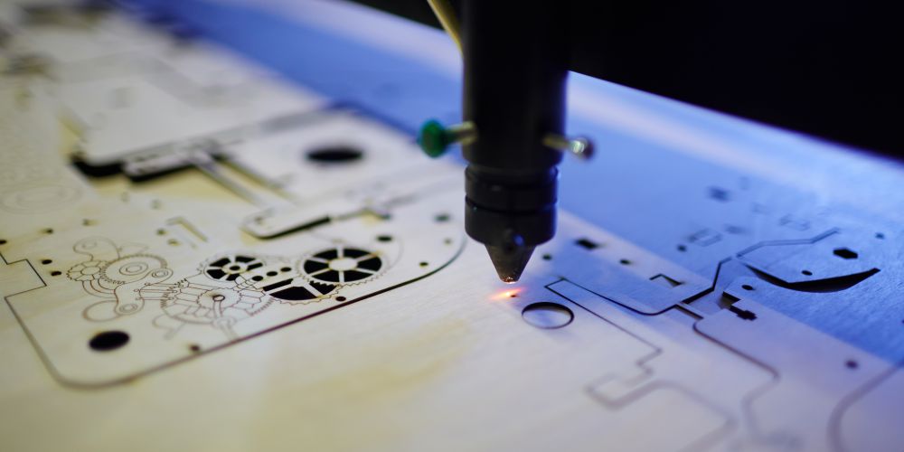
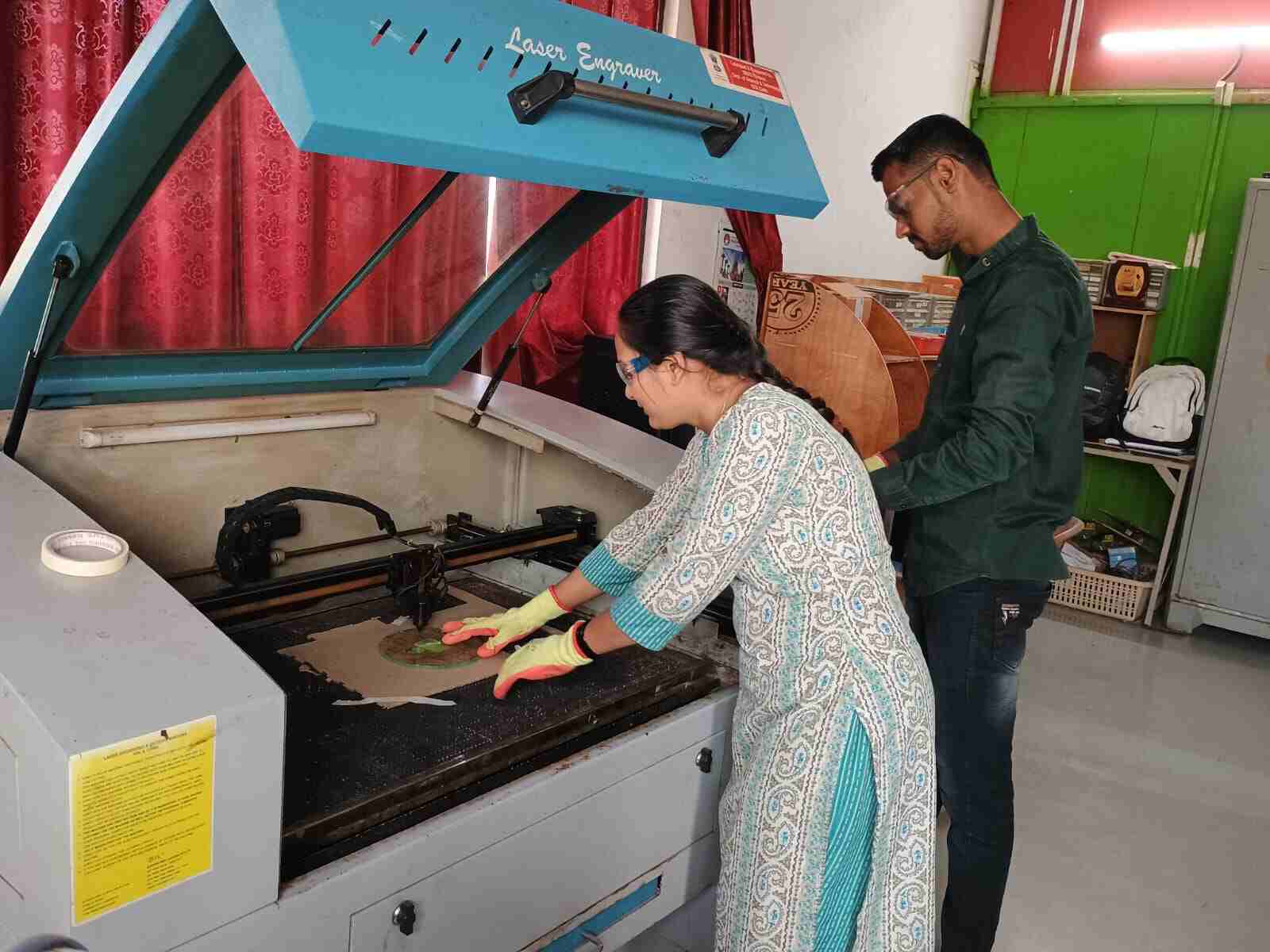
While, Leser Cutter machine The SIL CO2 Laser Cutter stands as a versatile tool frequently employed in fabrication endeavors. Its operation relies on harnessing a potent laser beam to meticulously slice through various materials with precision. Its utility spans across cutting wood, plastic, fabric, and select non-metallic substances. Embraced by diverse industries such as signage production, prototyping, and jewelry crafting, it holds a pivotal role. Noteworthy is its capability to execute intricate designs with finesse. Facilitated by computer software, users can conceptualize their cutting designs and exert control over the machine's execution. However, prudence is paramount in its utilization, given the inherent hazards of lasers. Adherence to safety protocols alongside routine maintenance routines, including cleaning and inspections, is imperative. In sum, the SIL CO2 Laser Cutter emerges as an indispensable asset for achieving precise fabrication across various domains.
Group Assignment Brief
We have a group assignment about laser cutting machines. In this assignment, we need to conduct various trials and experiments to learn about the SIL CO2 Laser Cutter. The tasks we need to cover in this assignment are as follows:
Objectives of the Group Assignment:
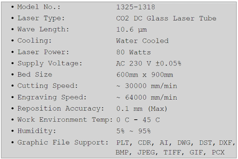
Understanding the machine's specifications and operation.
Understanding the cutting process and how it varies with different power and speed settings.
Identifying safety precautions that must be observed during machine operation.
Calculating the kerf at each power and speed setting.
Concluding the optimal speed and power settings for the machine's cutting operations.
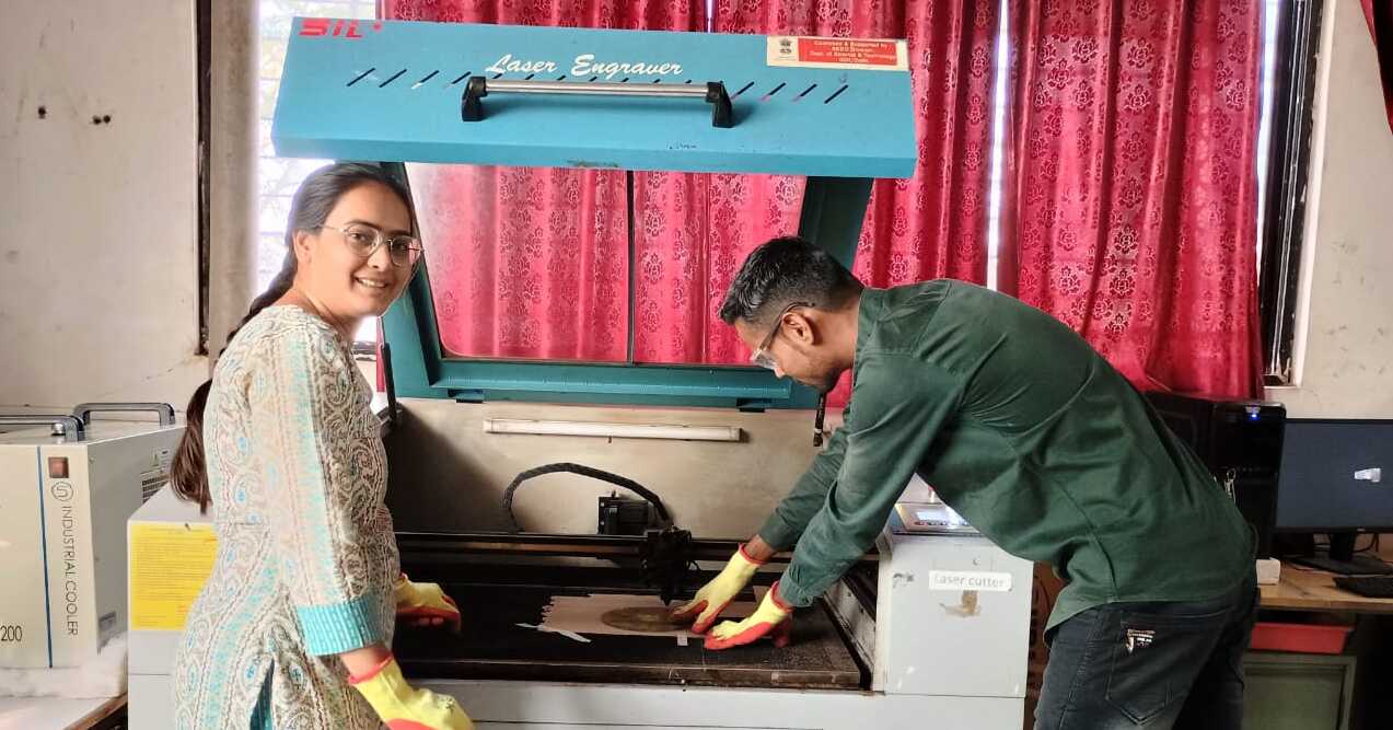
About VA Fablab Laser Machine
SIL laser engraving machine is versatile & finds application in signage, indoor & outdoor advertisement, art & craft, gift, shoes, toys, garments, model cutting, papers & packaging, wood & MDF cutting industry, interior, decorators and many more. SIL built laser engraver which is engineered & manufactured in india. SIL laser systems can be configured with two types of lasers, Glass Tube & Metal Tube. Glass Tube: The glass tube lasers are of very high quality, compact and come with warranty period of 6 months. Metal Tube: All metal tube lasers are RF excited with option of water cooling. Metal tube covers a warranty of 24 months. SIL series incorporates DSP based stand alone control system for offline work with 32 mb file space & easy to use printer driver software. The machine can print directly from AutoCAD, CorelDRAW, Photoshop etc. Printing real pictures, deep engraving, gradient engravings are the main features. High speed belt drive plotting unit with precise micro stepping drives. Rotary, Image Auto Tracing Camera, Two Laser Head, Four Laser Head, Honey comb are optionals Working table: 1300 X 2500 mm/ 1200 X 1200 mm/ 1300 X 900 mm/ 600 X 900 mm/ 600 X 400 mm.
 |
 |
Cutting Power and Speed Test
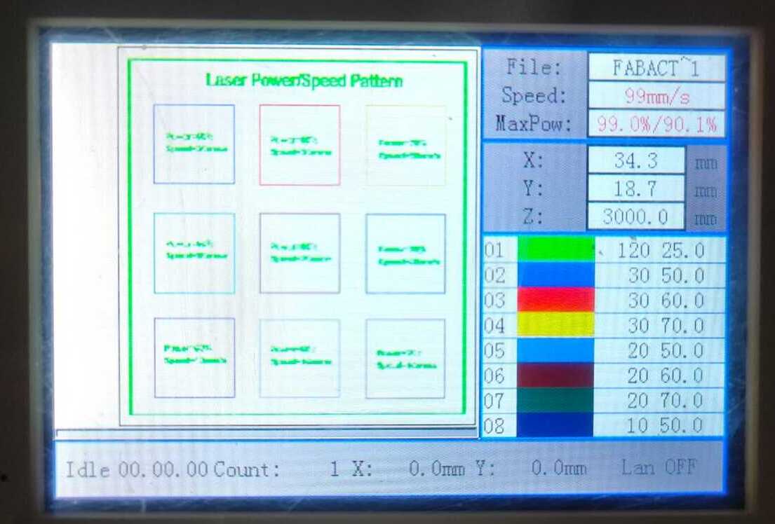
First, we discussed and planned the design for laser cutting. We created the design using SolidWorks. In SolidWorks, we saved the design file in DXF format. To import the design into the laser cutting machine, we used the RDWorks software. We imported the DXF file into RDWorks and then checked it, familiarizing ourselves with the functions of RDWorks. After importing our design, we applied offsets and assigned different power, speed, scan, and cut parameters for each type of cut, using different colors to denote each square. Finally, the file was prepared as input for the laser cutting machine.
.png)
When operating the Laser Cutting Machine, it is crucial to observe several precautions to ensure safety:
- Avoid Hand Placement: Never place your hand between the lenses when the laser beam is turned on. This precaution is essential to prevent accidental exposure to the laser beam.
- Keep Door Closed: Ensure that the machine's door is always shut closed while the laser cutter is in operation, either cutting or engraving. This helps contain the laser and ensures safety during the process.
- Wait Before Opening Door: After completing the cutting or engraving job, refrain from immediately opening the machine door. Allow time for the smoke generated during the process to vent out through the exhaust fan. Inhaling this smoke can be hazardous to health.
- Avoid Certain Materials: Do not attempt to cut or engrave materials such as Polycarbonate (PC), Lexan sheets, any material containing chlorine, PVC (Sintra), Vinyl, Glass, Fiberglass, Carbon fiber, etc. These materials may contain compounds that pose health risks when processed with the laser cutter.
By adhering to these precautions, users can operate the Laser Cutting Machine safely, minimizing potential risks associated with laser cutting processes and materials.
Turning ON the Laser Machine
As our Fablab is located in the small hamlet of Pabal, 60 km away from the main city of Pune, there is sometimes a variation in current. Therefore, we must ensure to connect our machines with a stabilizer and inverter for smooth, trouble-free operation. We then proceeded to switch on the laser machine, compressor, and chiller. Next, we imported the file by connecting the pendrive to the machine and set the material for cutting.
CardBoard, Plywood and Acrylic Cutting Test
Next, we imported the file by connecting the pendrive to the machine and set the material for cutting.We then placed and clamped the material properly on the machine working bed.
 |
 |
We adjusted the focus of the laser by setting the Z-axis, maintaining a 6mm standard clearance between the nozzle head and the workpiece.
In the next step, we set the origin to the desired area on the worksheet.
After locating the origin, we traced the frame of the file working area to check the outline of the work area.
After confirming that the frame is suitable for cutting, we initiated the cutting operation by giving the command.
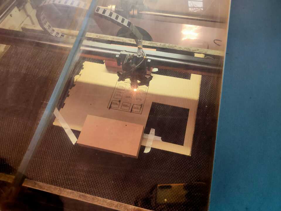
Then, we observed the cutting operation until it finished.
After the operation is finished, we turned off the laser button (but the main supply to the machine was on).
We then waited for a couple of minutes to let the smoke exhaust out of the chamber before taking out the cut piece of the machine.
Results and conclusion:
Below are the snapshots of Cardboard, Plywood and Acrylic Looking at the results, we concluded the ideal power and speed for the laser cutter. The results and Power Speed Chart is documented in excel form mentioned below.
Cardboard
 |
 |
Plywood
 |
 |
Acrylic
|
 |
After performing this test we have tabulated our observation and reading in the table mentioned below, we came to a conclusion;
Optimum Power and Speed:-
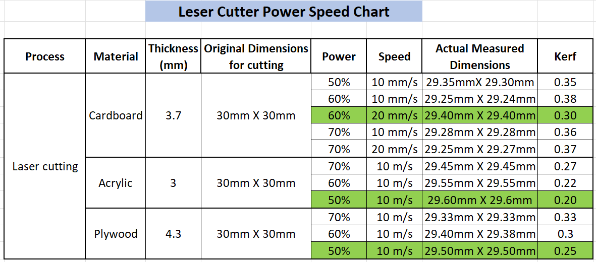
Cardboard 3.7mm = Power=60% ; Speed=20mm/s
Acrylic 4.3mmPower=50% ; Speed=10mm/s
Plywood 4.3mmPower=50% ; Speed=10mm/s
Kerf Calculation for CardBoard, Arcylic and Plywood
 |
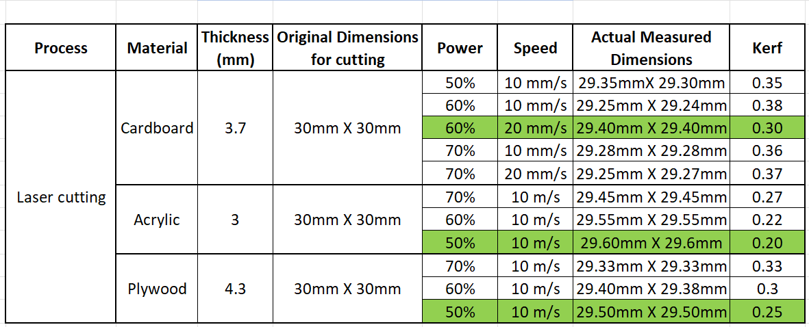 |
We proceeded to calculate the kerf for Cardboard, Plywood and Acrylic sheets by meticulously measuring the actual dimensions and comparing them to the designed dimensions.
The kerf value was determined by assessing the difference between these two dimensions.
It's noteworthy that the kerf value tends to increase with the power used; hence, a careful analysis was conducted to correlate the power settings with the resulting kerf dimensions.
Scanning Test on Acrylic Sheet
 |
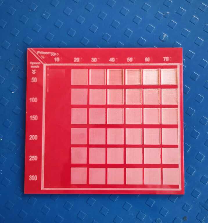 |
Scanning Observation
We have made a SCAN test pattern and tested it on Acrylic sheet of 4.3mm .
Increasing the power and reducing the speed led to a significant downside: deep engraving at the cost of engraving quality. Conversely, employing low power and high speed surprisingly resulted in superior engraving quality. For instance, at a speed of 300 and power set to 20%, we observed a remarkably smooth and clean engraving. In contrast, when the power was cranked up to 70% and speed set at 50mm/s, the engraving turned out to be rough and excessively deep.
We observed that as our laser was old now, it was not able to properly scan at power 10% or below.
Learning
This assignment was all about using a cool machine called the SIL CO2 Laser Cutter for cutting stuff. We learned how to make it work, what it's good at, and how to keep ourselves safe. We played with different materials like cardboard and acrylic to see how the machine cuts when we change its power and speed settings. It was like a little science experiment! We also used computer programs like SolidWorks to design what we wanted to cut. The best part was figuring out the best settings for making things just right. It was a mix of playing with the machine, solving problems, and learning how to use computer programs to create cool stuff.