Week 2 assignment: Computer-Aided-Design
Summary
This week I had to work an image using a software Raster and Vector, and a 3d model of my final project in a software for that. For the raster software I used Adobe Photoshop and for the vector I used Inkscape. For the 3d model, I used Autodesk Fusion 360.
Raster software: Adobe Photoshop
Adobe Photoshop is a raster image editing program. I used it to work with an image composed of a grid of individual pixels. This image is known as raster image or bitmap image. It allowed me to edit my principal image, modify the image in various ways like resizing, cropping, rotating, changing resolution, and others. It is capable of opening and saving images in a variety of file formats, such as JPEG, PNG, TIFF, BMP, GIF, among others. I used a trial free version accessing the software for 7 days.
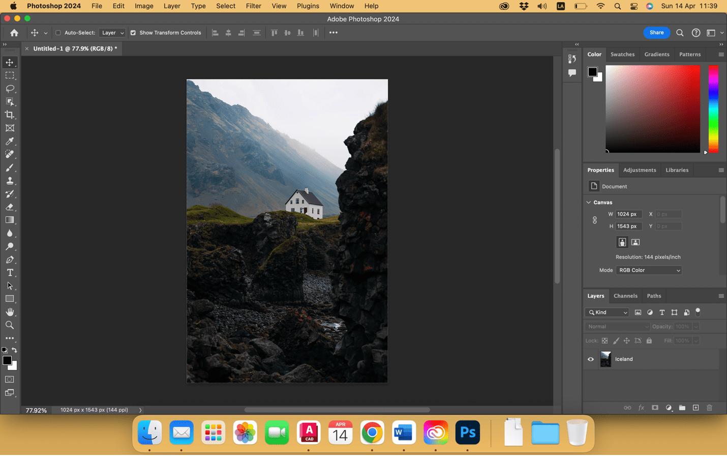
First, we open an image in Adobe Photoshop and select the part of the image we want to work with.
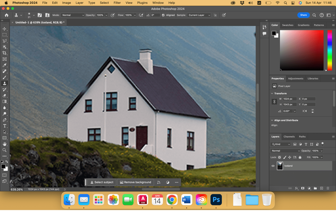
In this case we work with the clone tool because there are many textures in the image. To use this tool we will be selecting the part we want to clone with the Option + Click keys on the selection, then letting paste with another click on the area we want to delete.
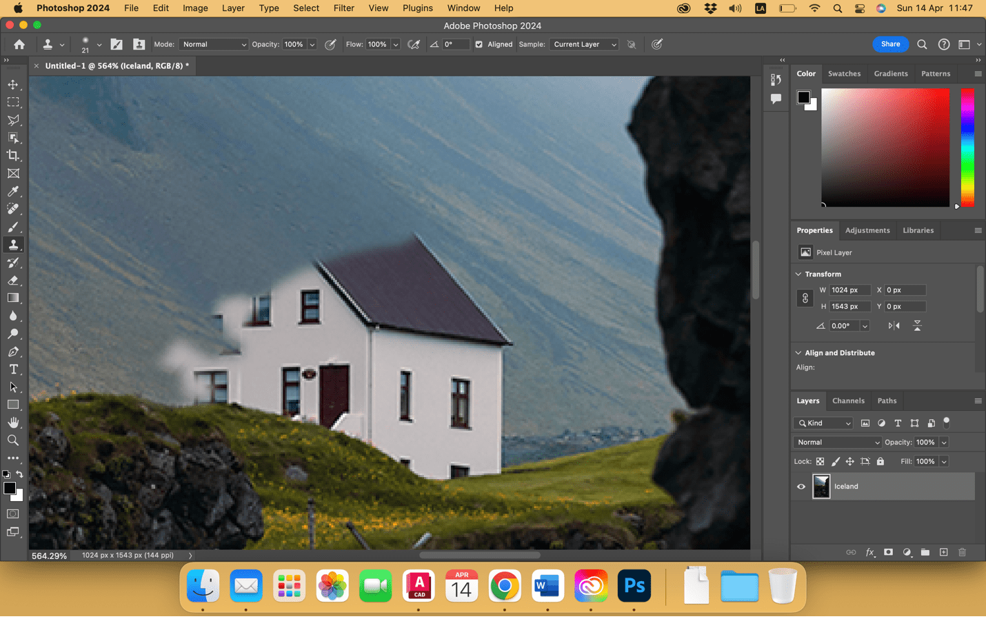
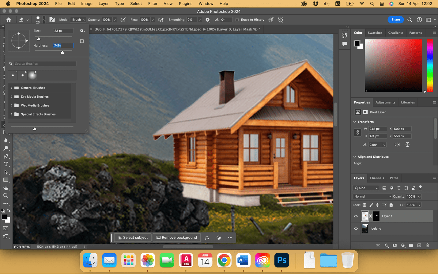
For this we are going to help ourselves by adjusting the size of the brush and the hardness, so we can play with cloning the image.

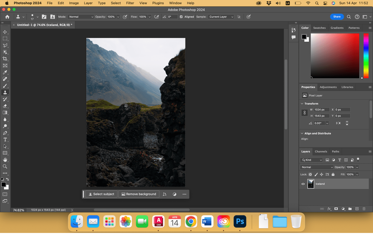
We continued working with the clonation until the house disappeared, like the following image.
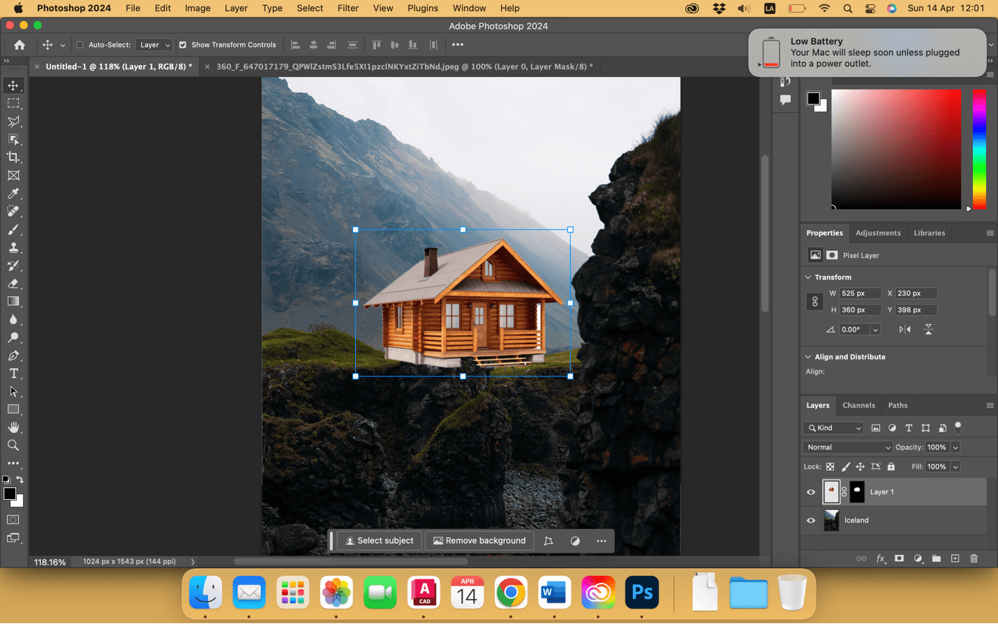
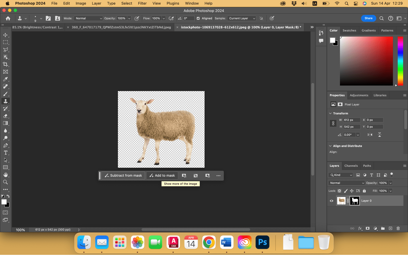
In another Photoshop worksheet we are going to open the image that we want to replace with, in this case the cabin. Here, together with the magic wand, we are going to select the image and remove the background.

Once it no longer has a white background and becomes png, we are going to select the layer and drag it to the first working hour.

Once dragged we are going to position it and with the Shift control we can regulate the size of the cabin and with the command shift move the perspective if necessary.
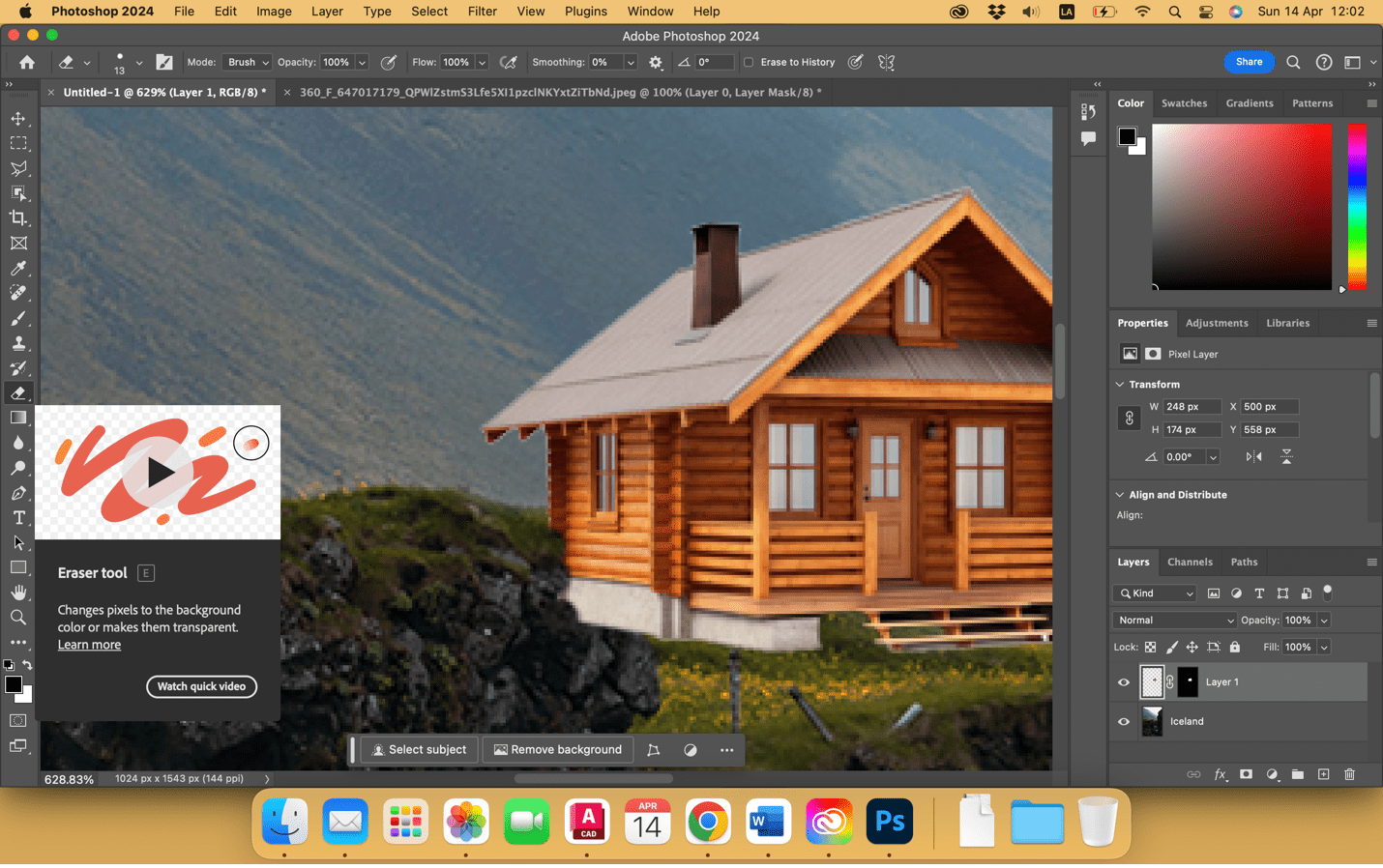
After that we are going to use the eraser and erase part of the cabin to make the idea that it is behind the rock, regulating the size and hardness of the working brush.
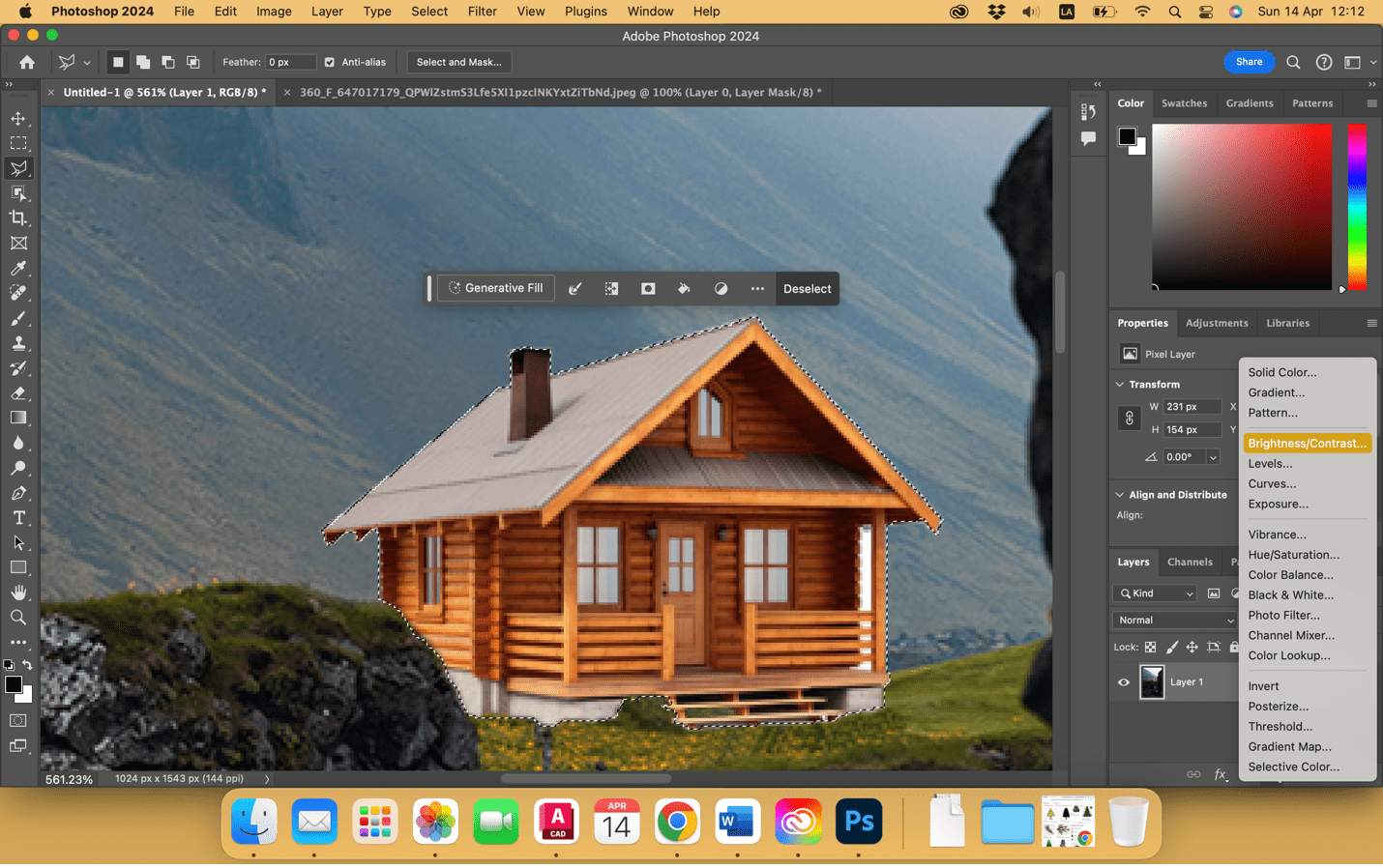
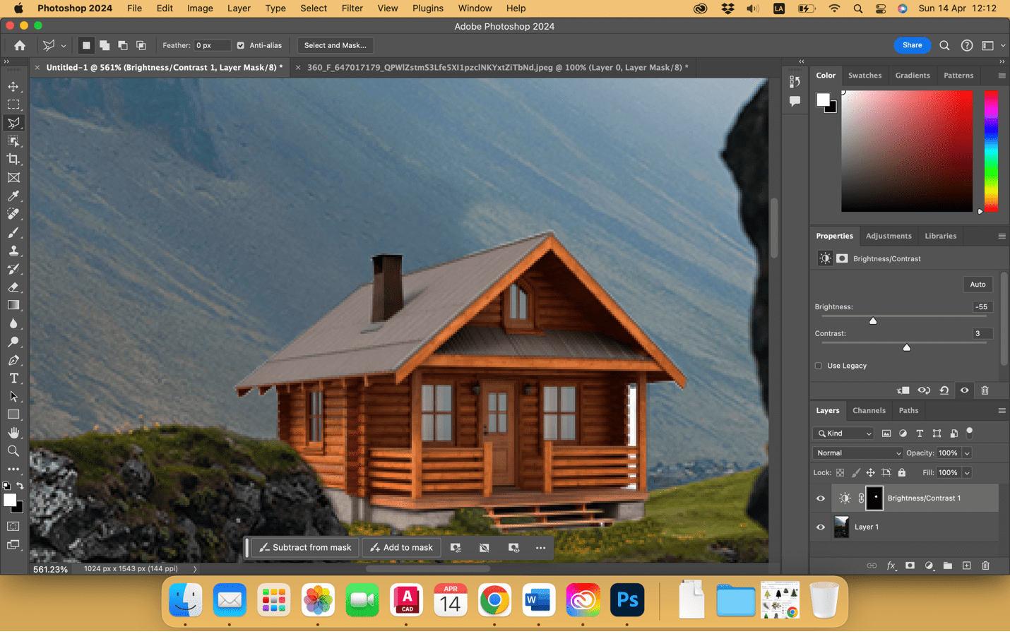
Then we are going to select the cabin to regulate the brightness and contrast of the image, since it has more light than our background image. It is important to select and apply this color change only to the cabin but not to the background image.
Once the brightness and contrast have been adjusted, we can control + E and join the layers (image layers).
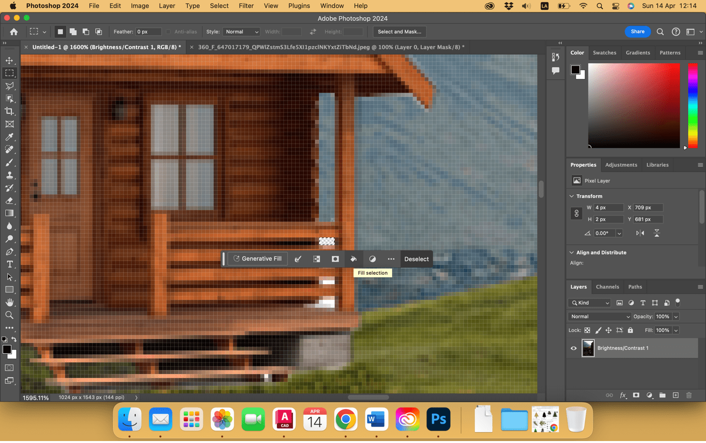
After that, we were left with white spaces of the cabin that we are going to select, delete and with the clone tool, we are going to add the background of the mountain.
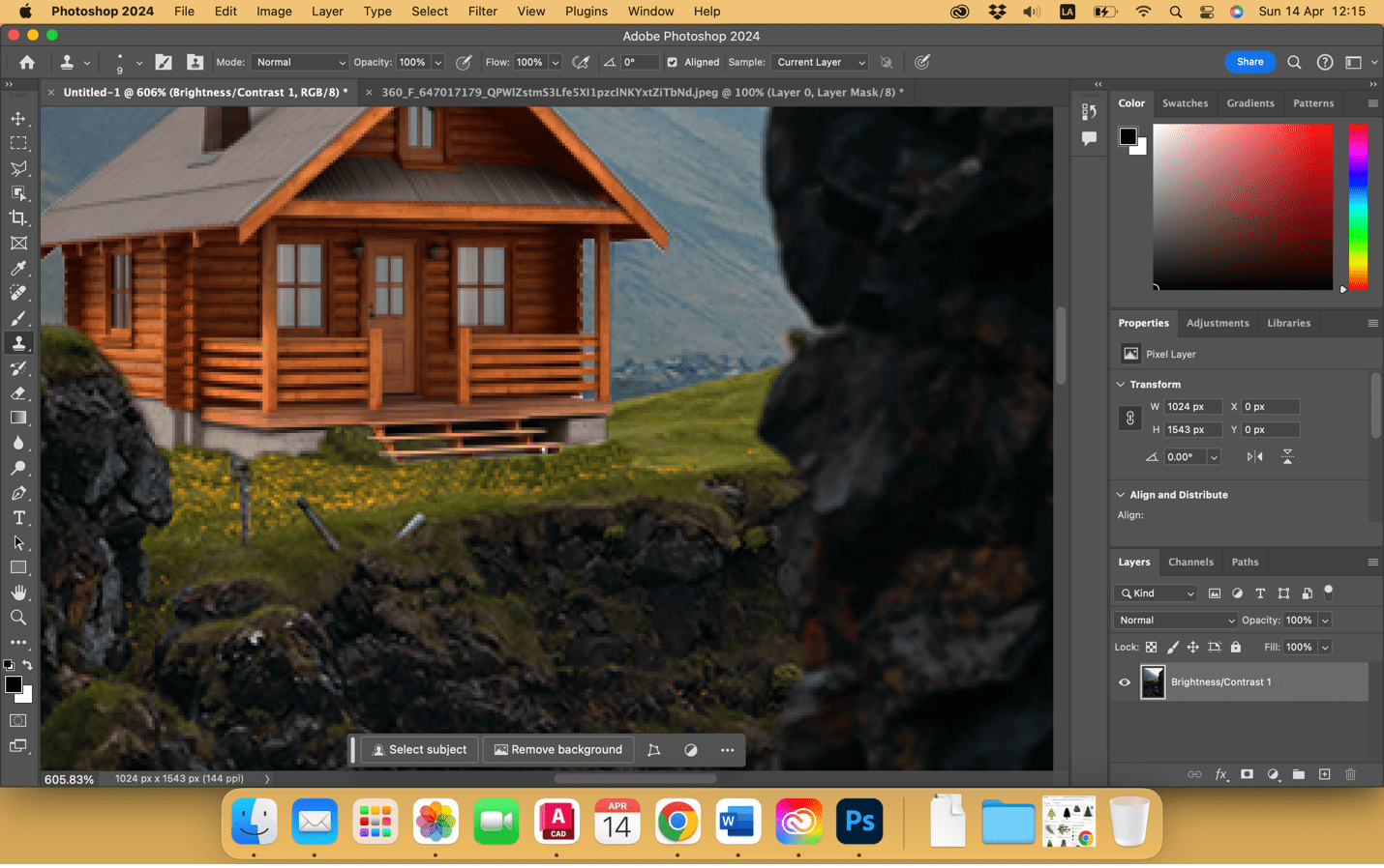
After that with the clone tool we are going to add more yellow flowers and garden to the floor to attach the house to the image. Finally the image looks like this. Now let's add one more element.
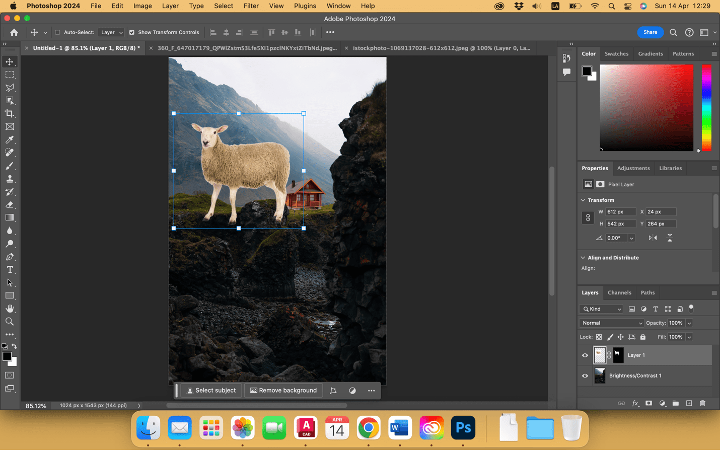
We are going to repeat the process now with a sheep, removing the background and dragging it to the main image. We should adjust the image to the background according to the size and perspective you need.
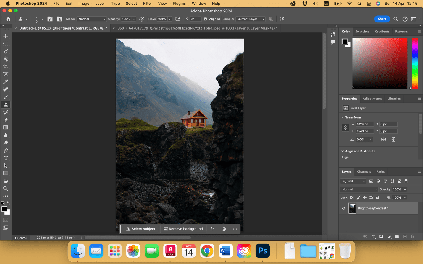
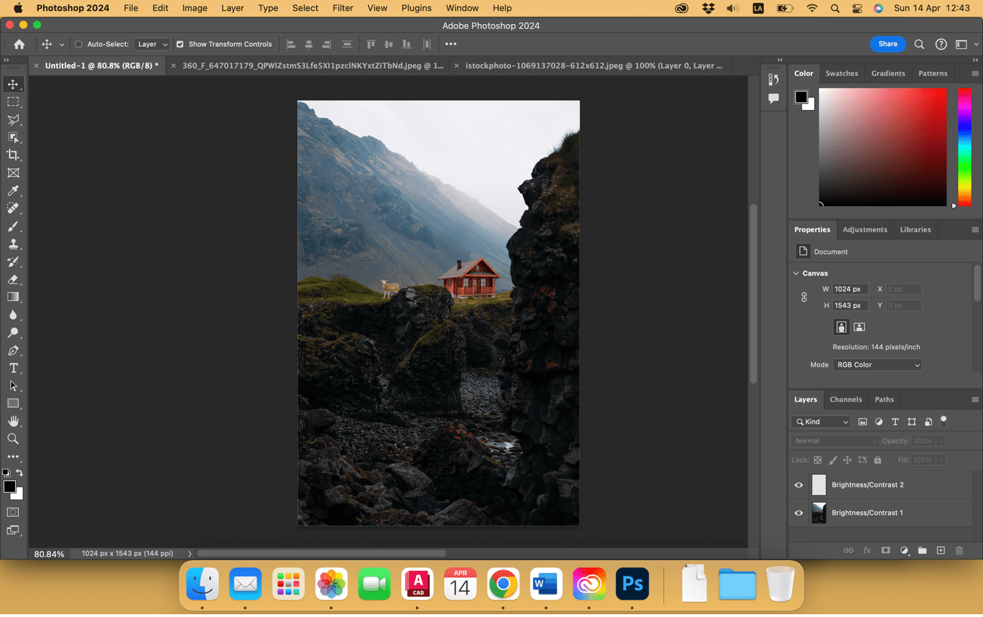
Finally, we got the final image after all the operations:
Vector software: Inkscape
Inkscape is a free and open source vector graphics editor for GNU/Linux, Windows and macOS. The main reason I chose it was because there is a lot of information of tutorials on the web and I could download it for free, working fine in a MacOS laptop.
The following work is about how to trace bitmap from an imported image from the webpage.
First, we have to import the image to the software to start working with it.
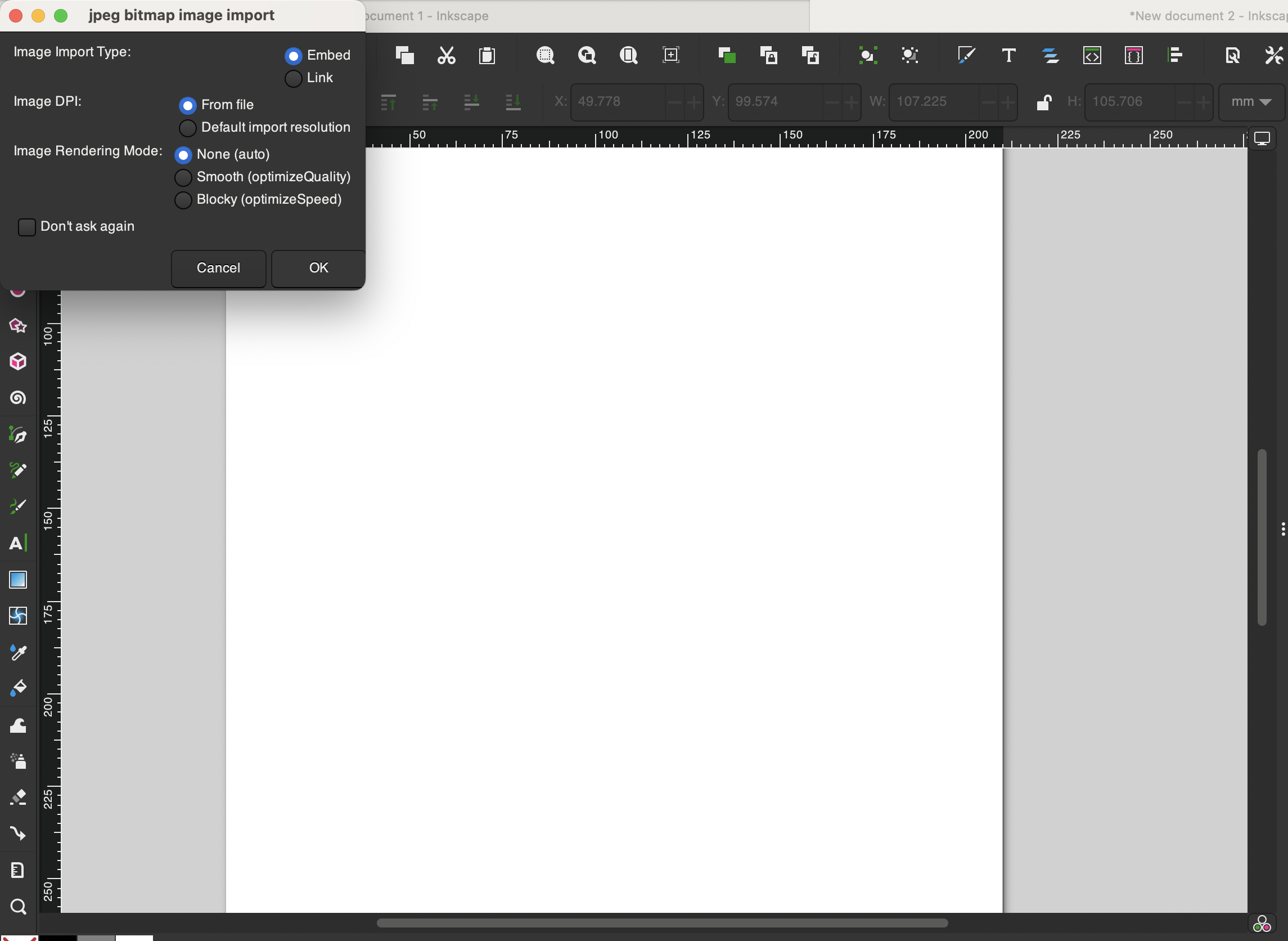

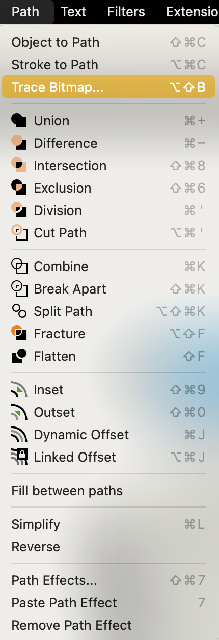
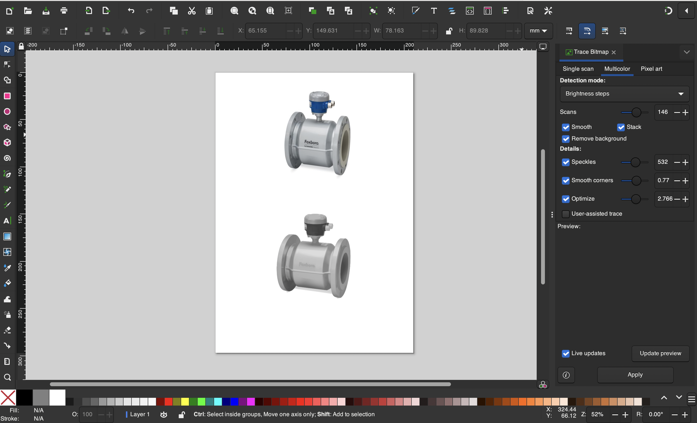
Once we are in this option submenu, we can vary parameters such as brightness cutoff, changing the threshold in the way is better for our image. We can also invert the image, changing the white colors into black.
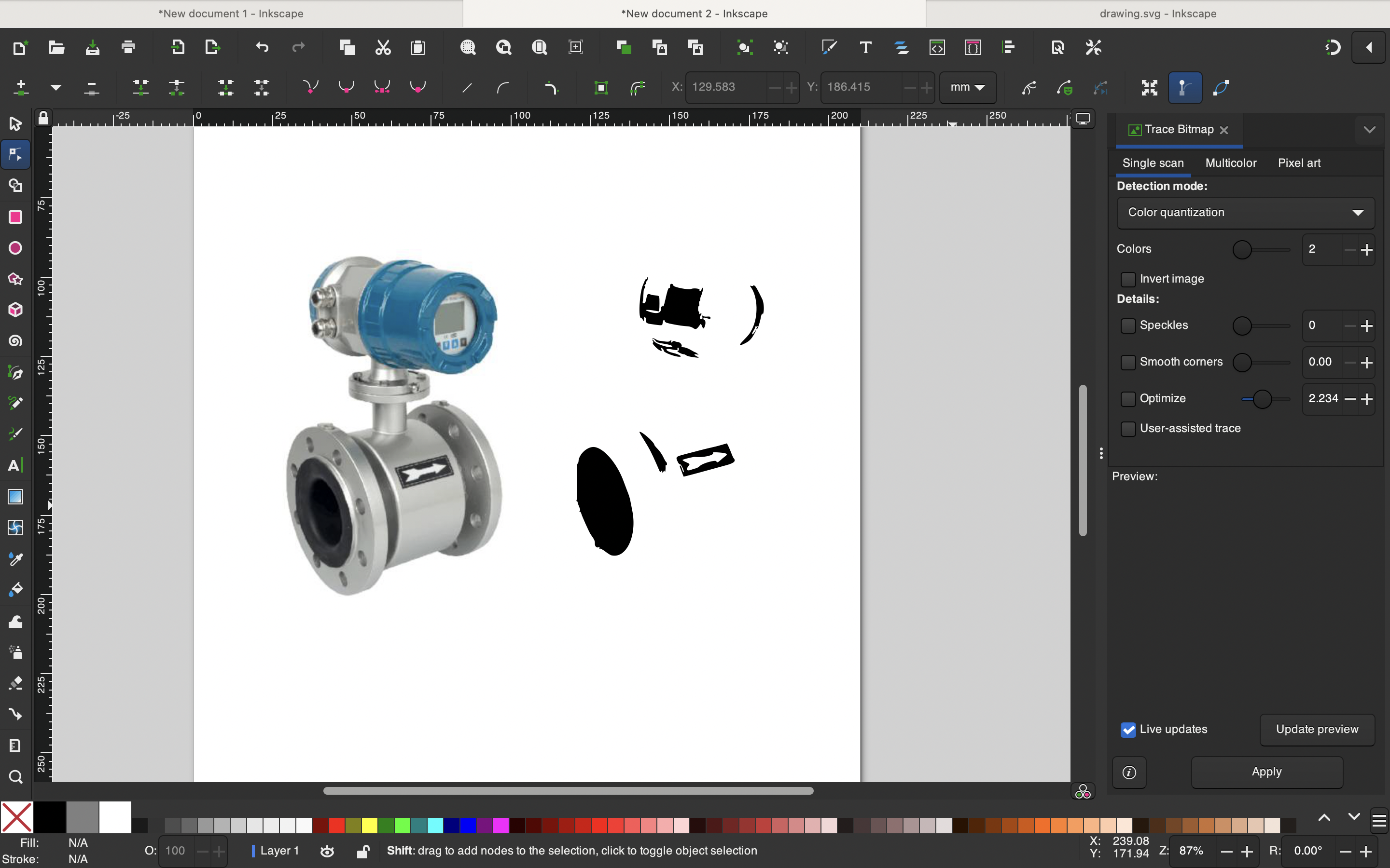
Also if you select the multicolor opcion, you can select how is the scan going to be performed, if you want it smoorh, stack or removing the bakground automatically.
With the option "live updates" with the check, we can see all the changes in real time and select the parameters that fit better for us.
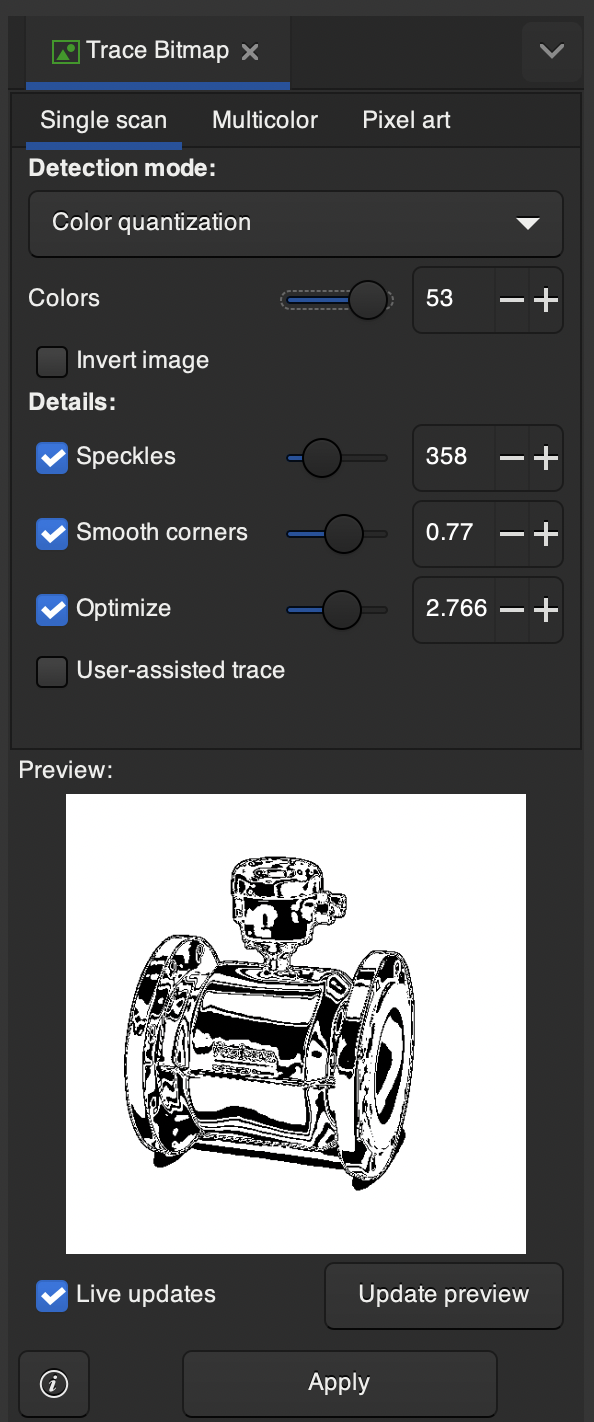
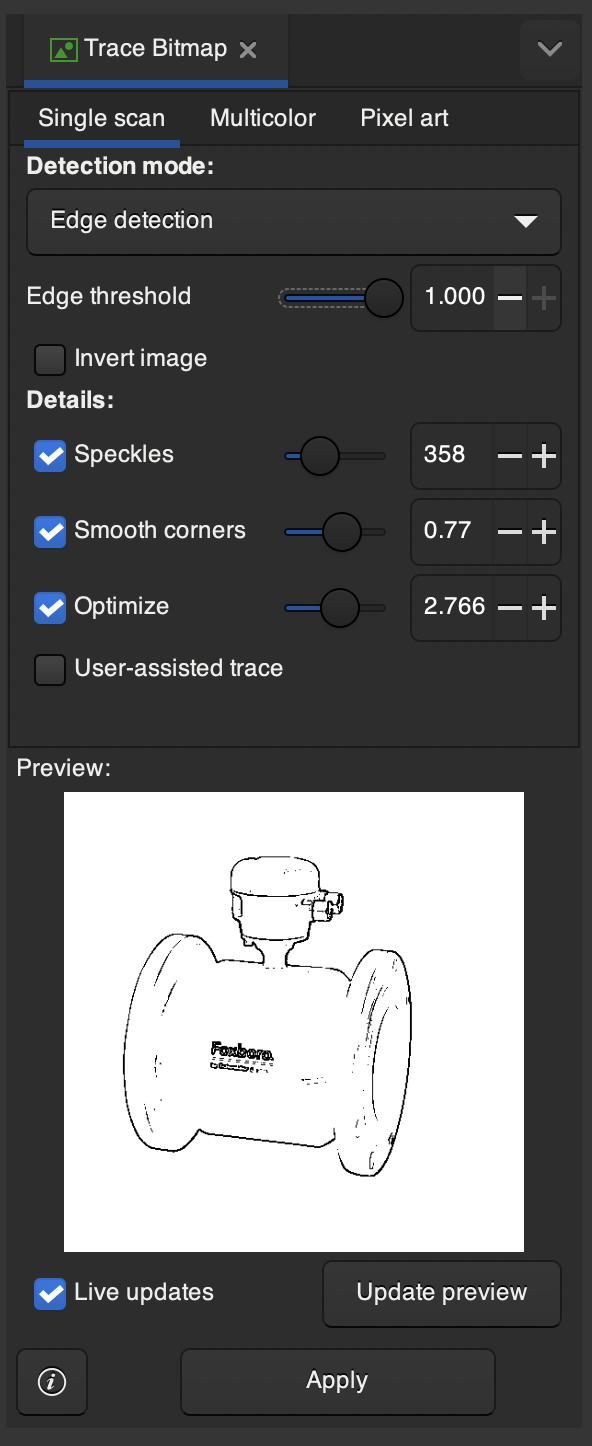
Finally, the image can be exported in a Svg for opening it in another software for another process.
3d software: Autodesk Fusion 360
Fusion 360 is a cloud-based 3D modeling software developed by Autodesk. It's widely used in industries like engineering, product design, and manufacturing for creating digital prototypes, simulating designs, and generating documentation. As a student, I can use it for free for one year and it works very good on my macbook.
I think it is a good software that integrates several fields such as design and manufacturing, where I can manage my projects online.
Process of the design of my final project: water leak detector.
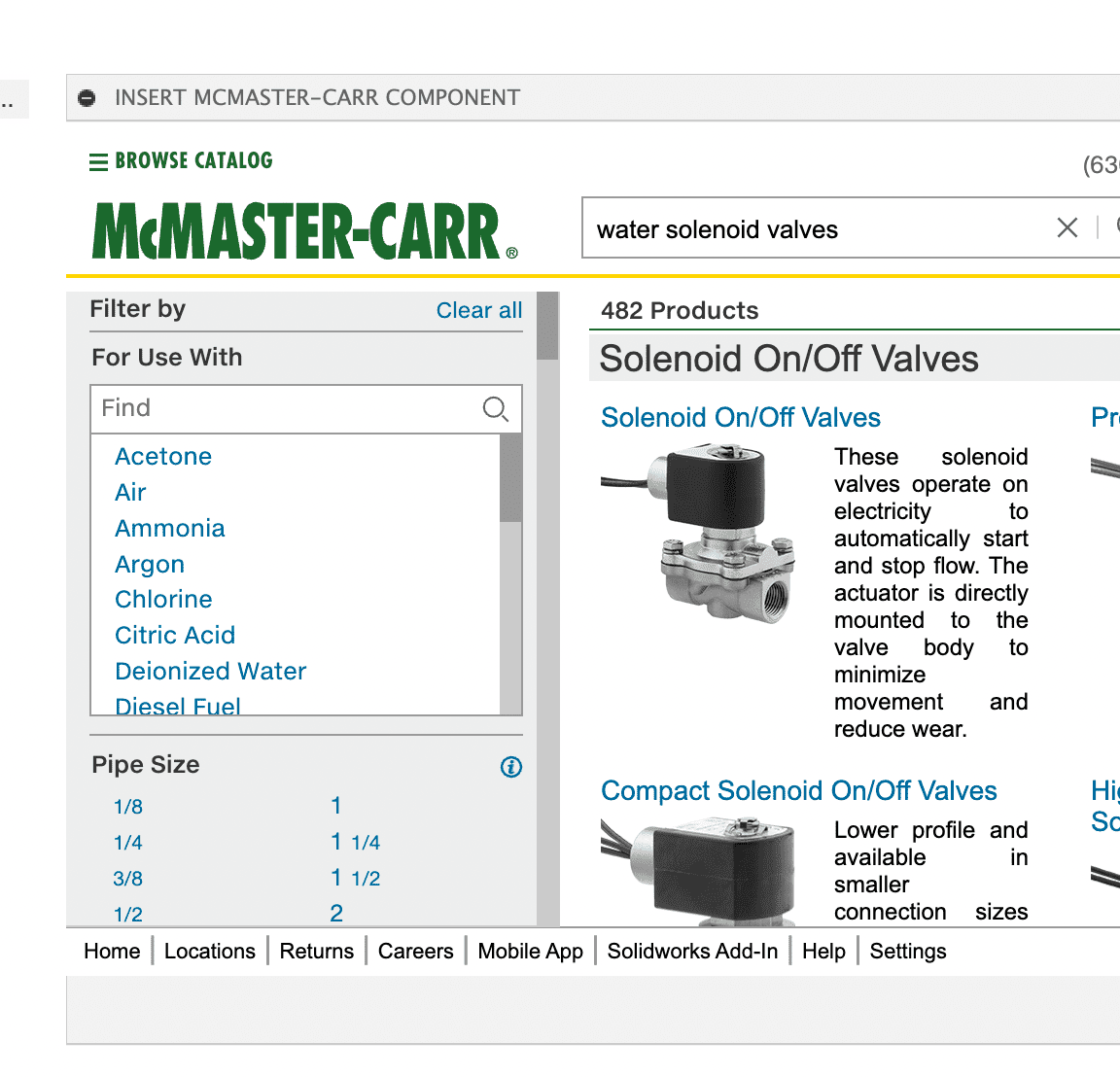
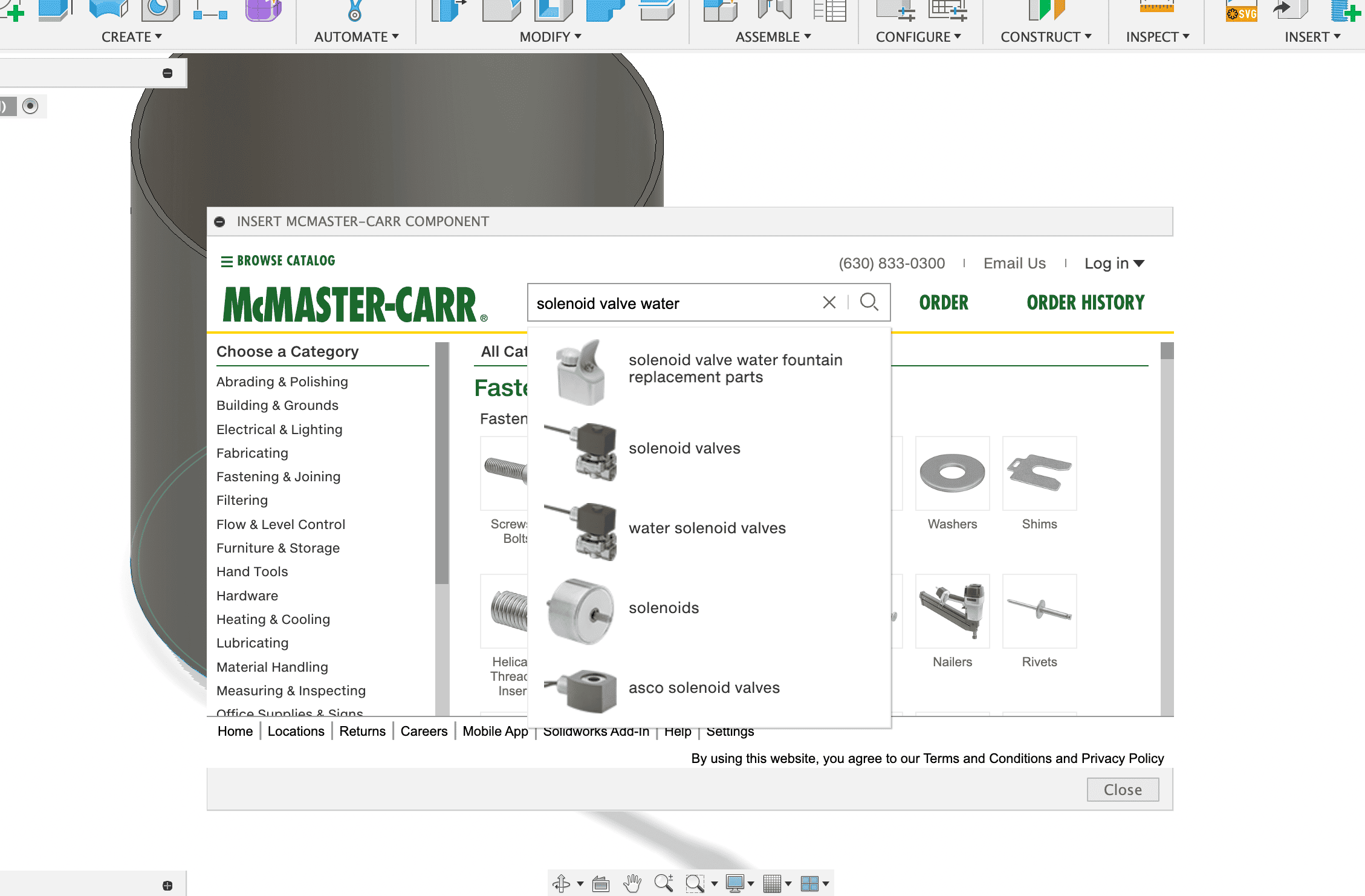
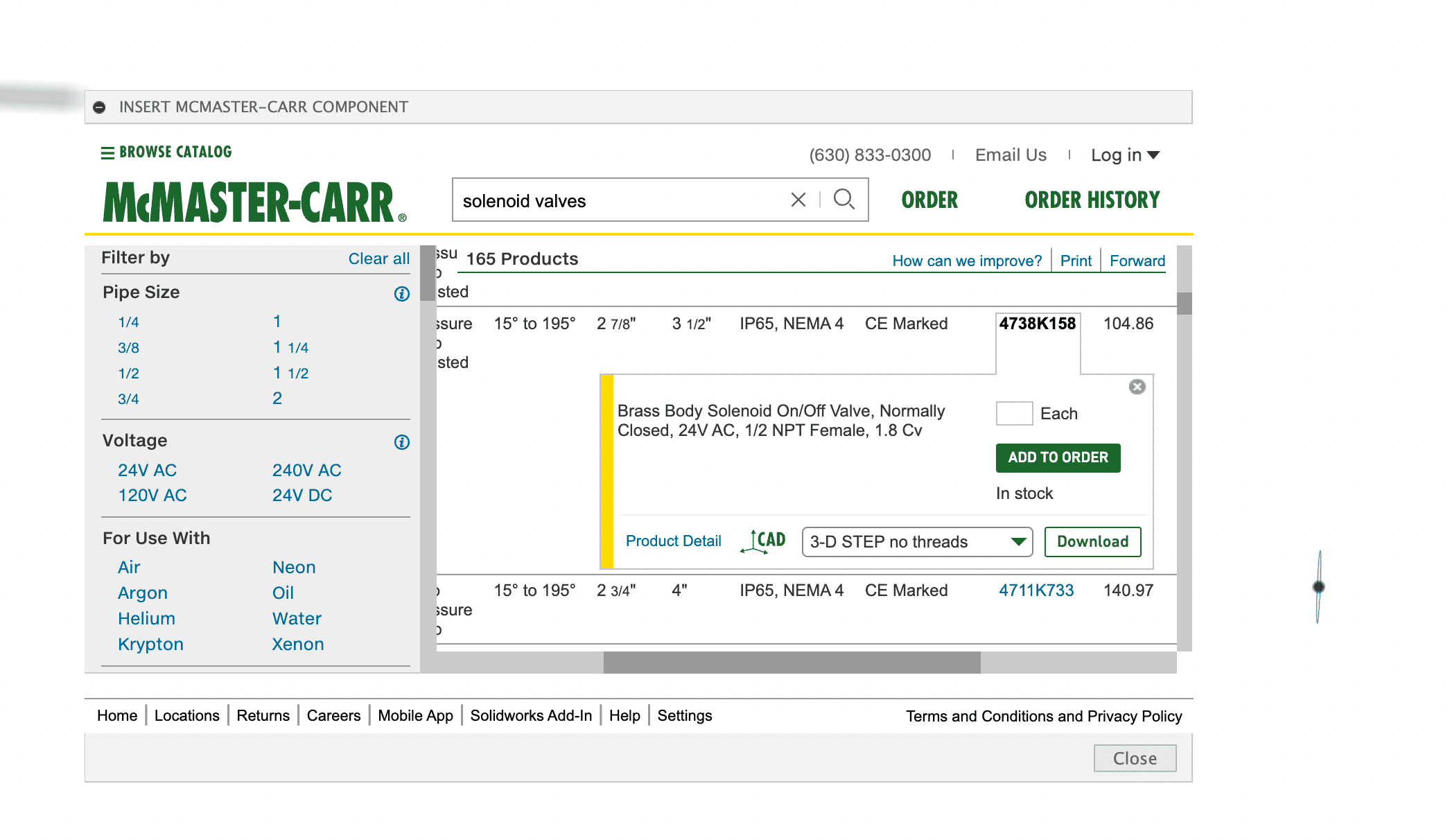
For this design I used the McMaster-Carr component. McMaster-Carr is a popular industrial supply company that provides a wide range of products, including hardware, fasteners, and mechanical components. In Fusion 360, the McMaster-Carr component feature allows you to easily access and insert 3D models of parts from McMaster-Carr's extensive catalog directly into your design. .
To use it, I had to:
Open Fusion 360 and the design where you want to insert the component.
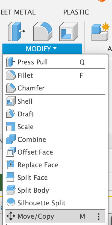
Go to the Insert Menu: Click on the Insert dropdown menu in the toolbar.
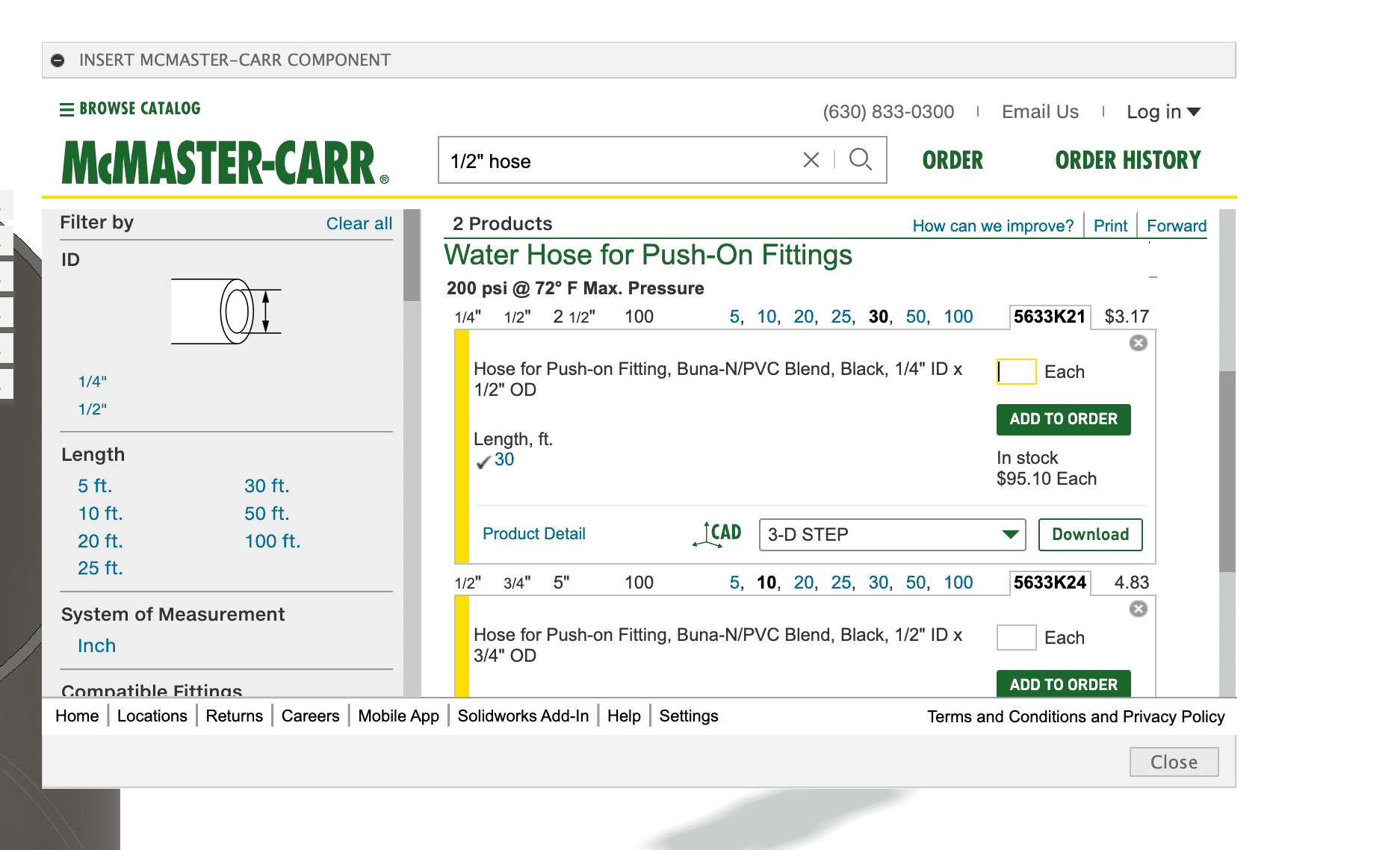
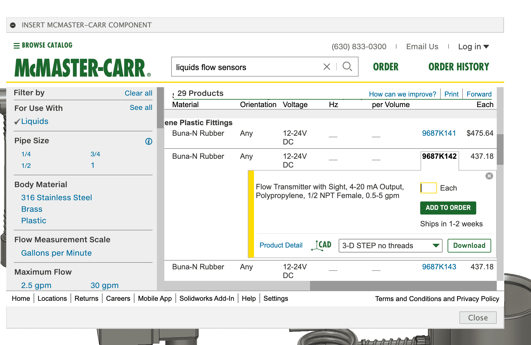
Select Insert McMaster-Carr Component: This will open a browser window within Fusion 360.
Browse the McMaster-Carr Catalog: Use the search bar or navigate through the categories to find the component you need.
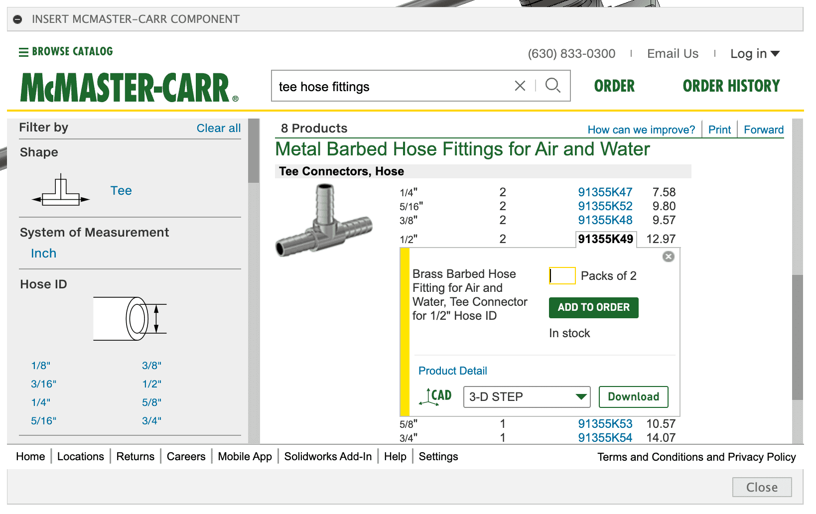
Select a Component: Once you find the desired part, click on it to open its detail page.
Download the 3D Model: On the detail page, you'll see an option to download the 3D model. Click on it and choose the desired file format (Fusion 360 will need the 3-D STEP model).
Insert into Your Design: The component will be inserted into my current Fusion 360 design workspace, where I can position and use it as needed.
The first thing I am adding is a tee connector for the union of the hoses. This tool now allows me to even select the diameter with which my module will work, which will be half an inch.
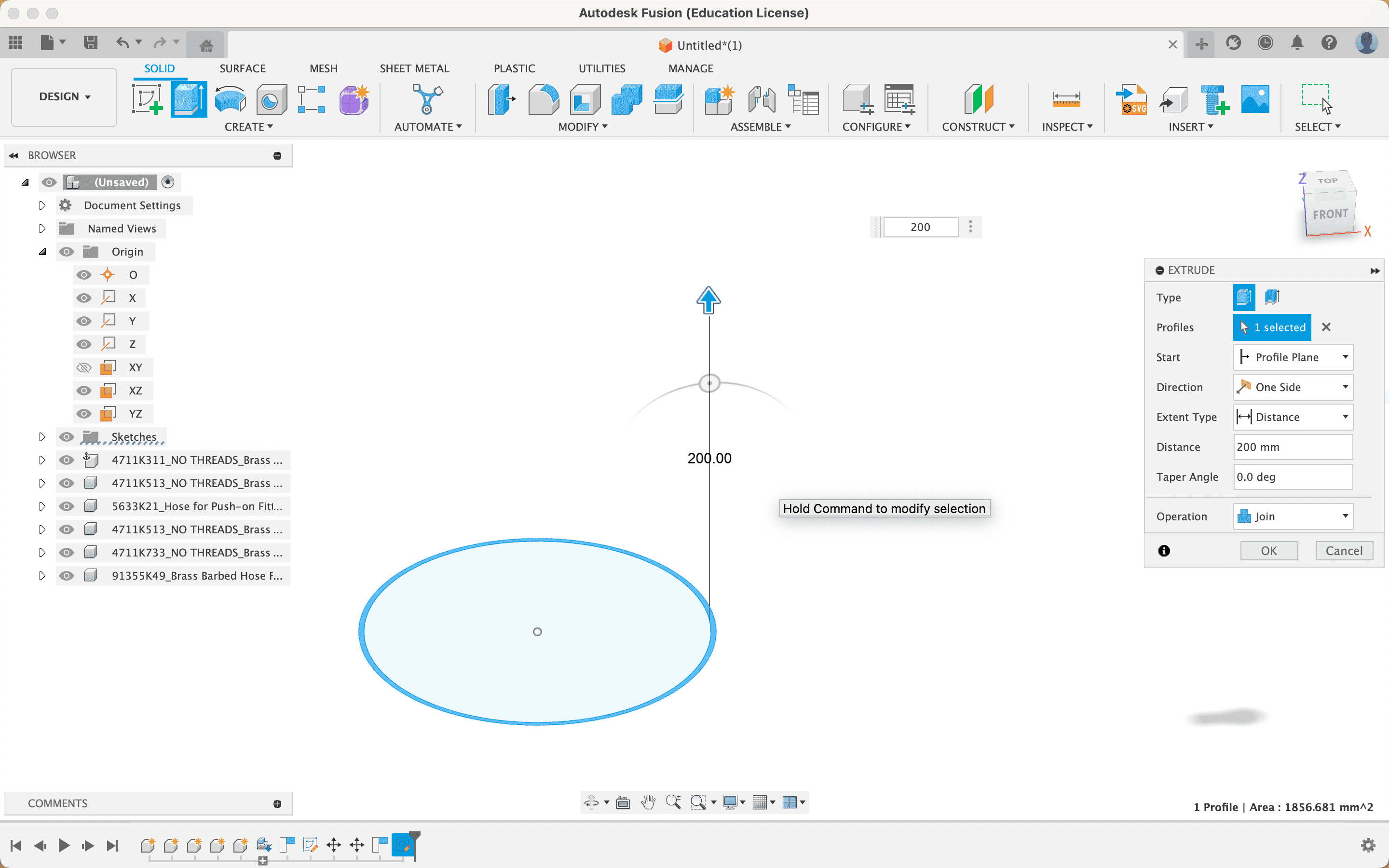
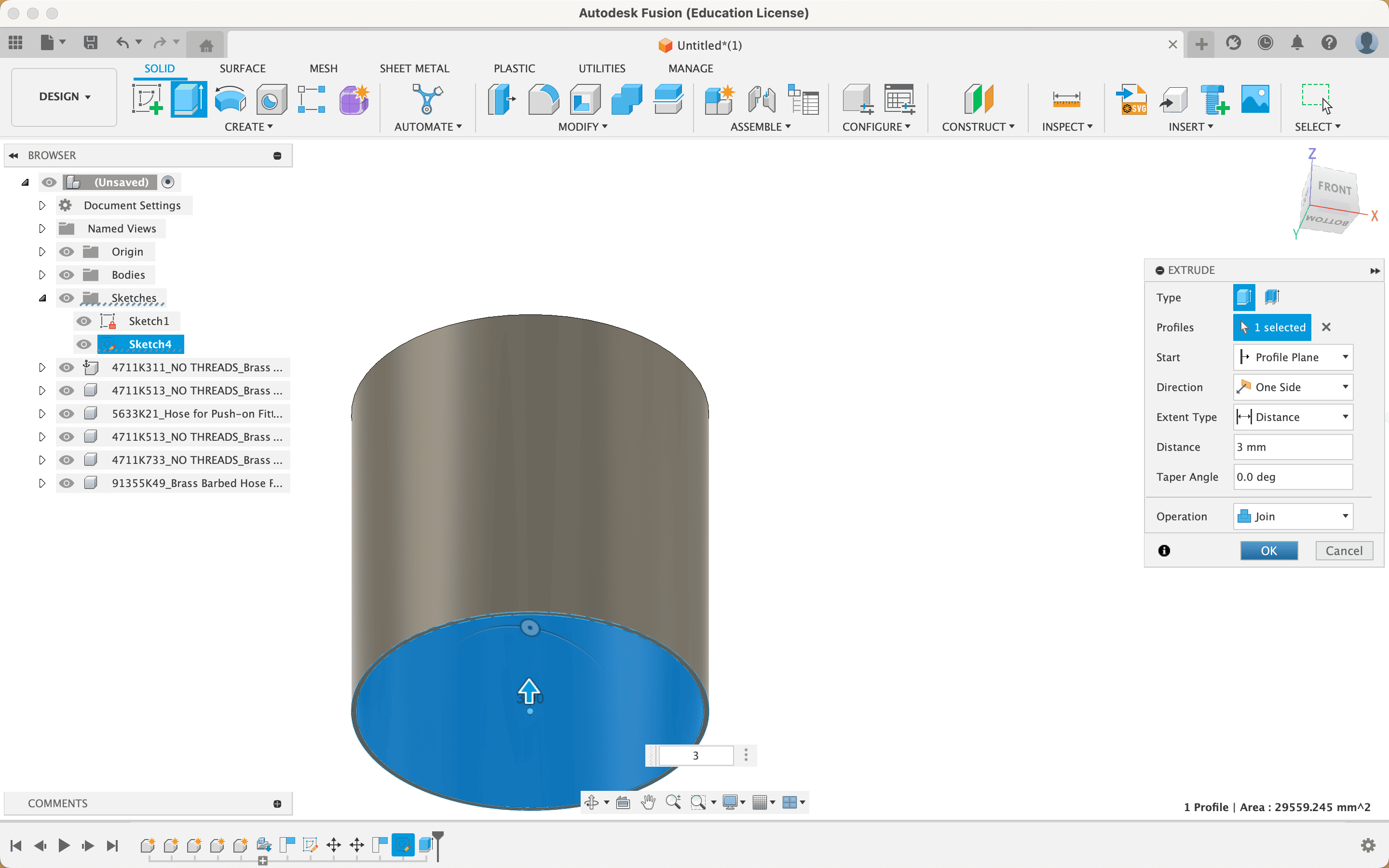
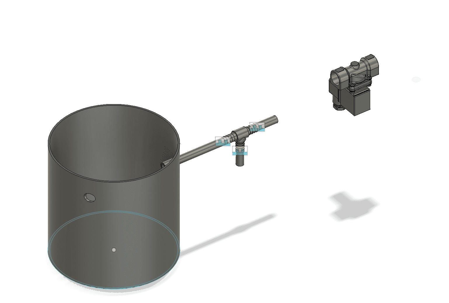
After testing that the entered design works, I am creating a tank that will store the water that recirculates through the module. To design this tank, first I make the sketch and then I give it an extrusion to define its height. In fusion 360, I can add each design and then later join it, unlike professional inventor software where I must have each design separately and then join them in the assembly section.
Next, I'm going in with a tee connector for the hose system I'll have.
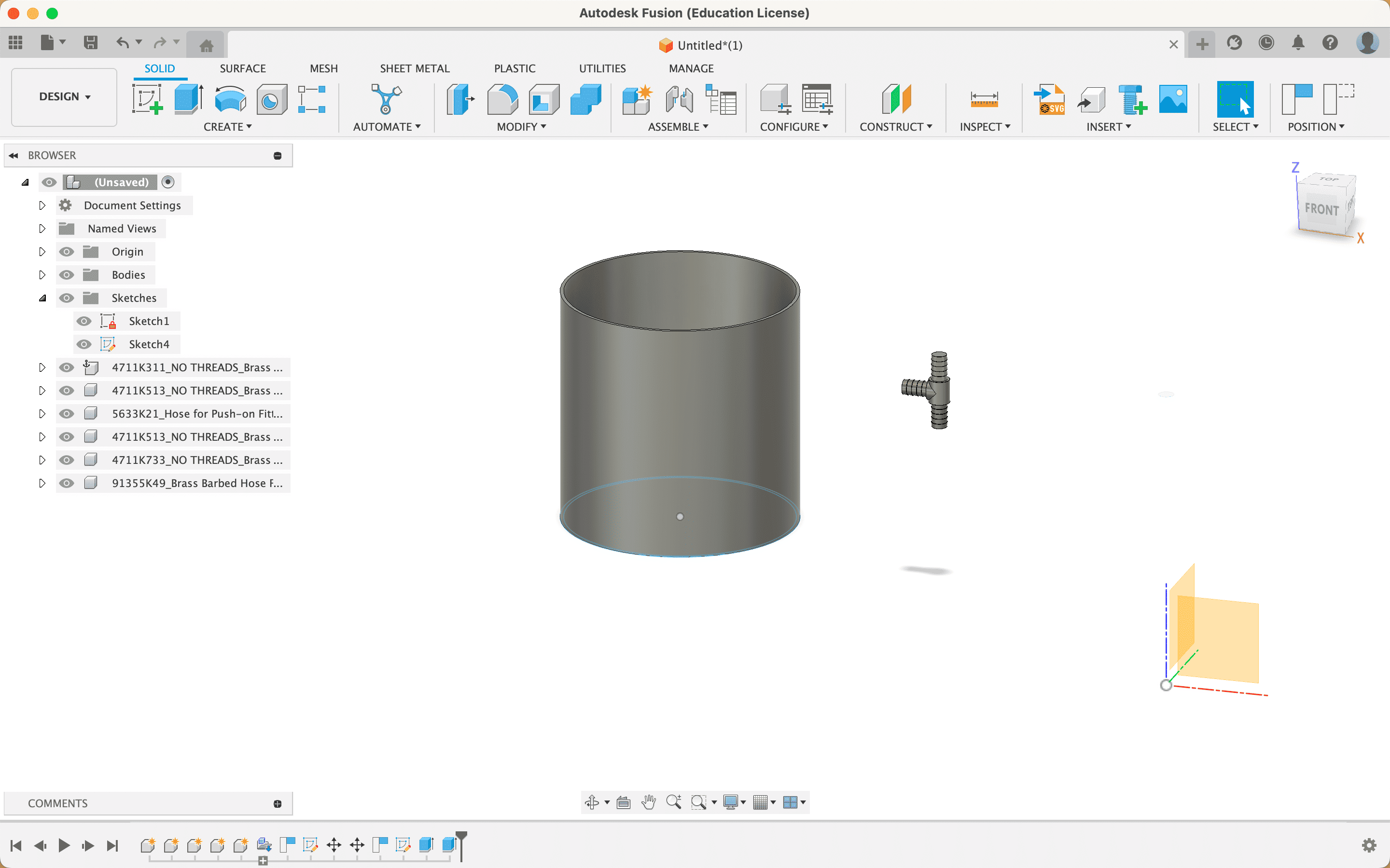
I insert the hoses the same way, using the McMaster-Carr component.
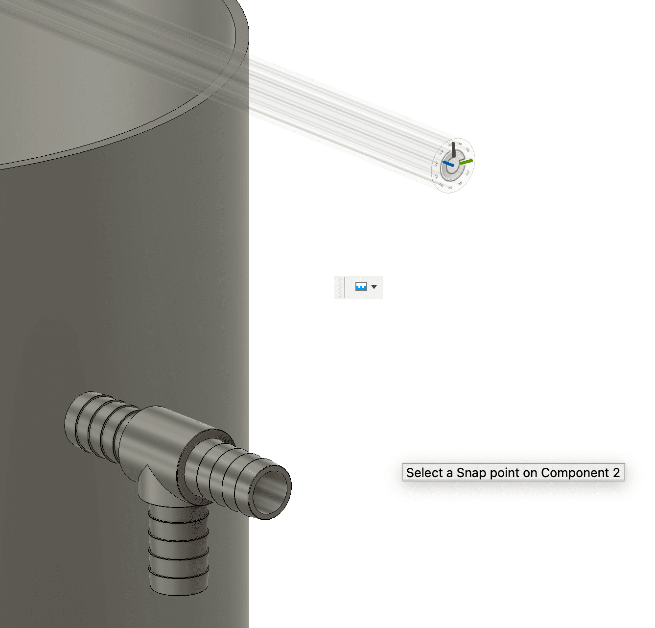
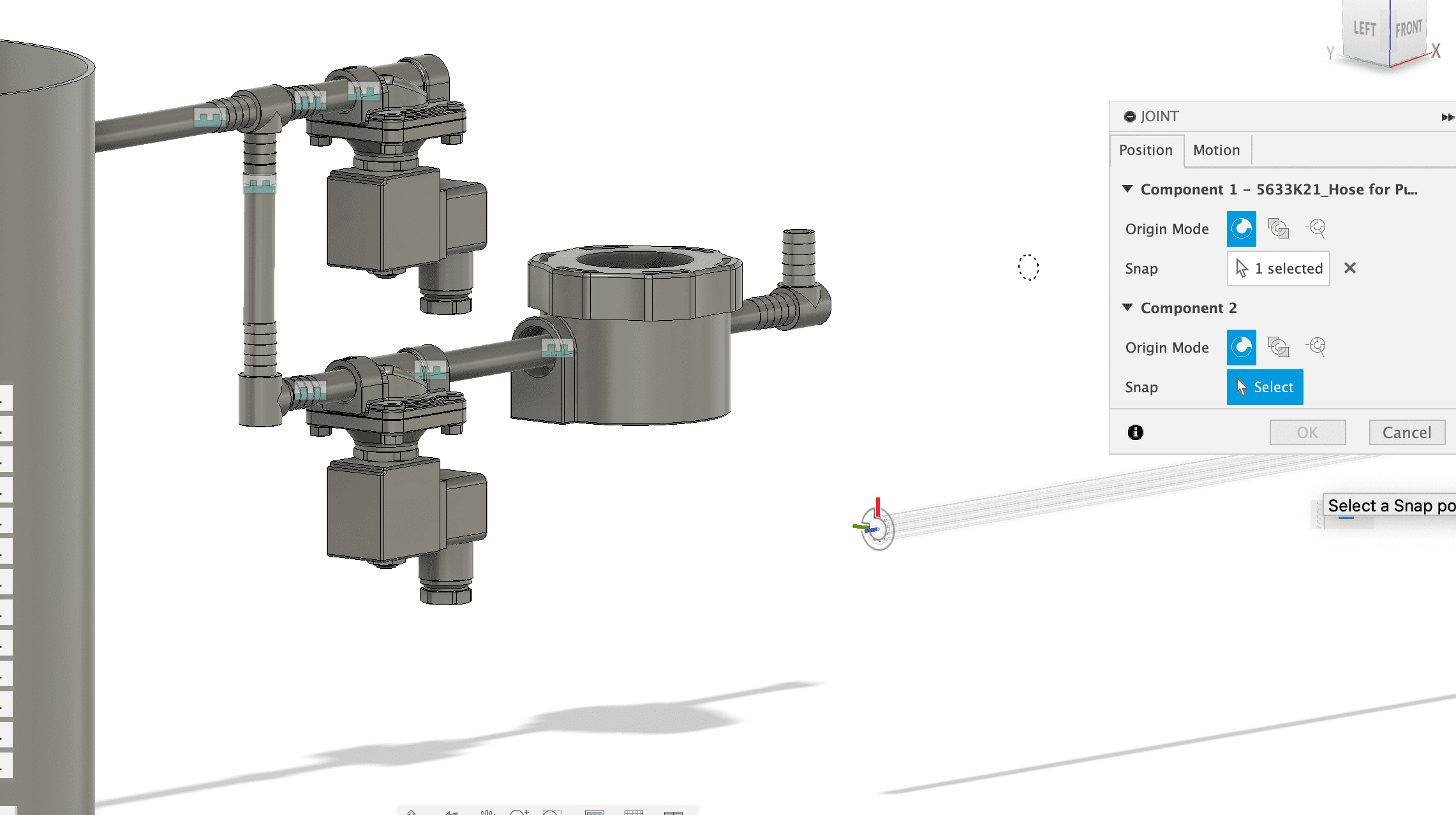
After having inserted the hose, I proceed to join it with the tee connector.
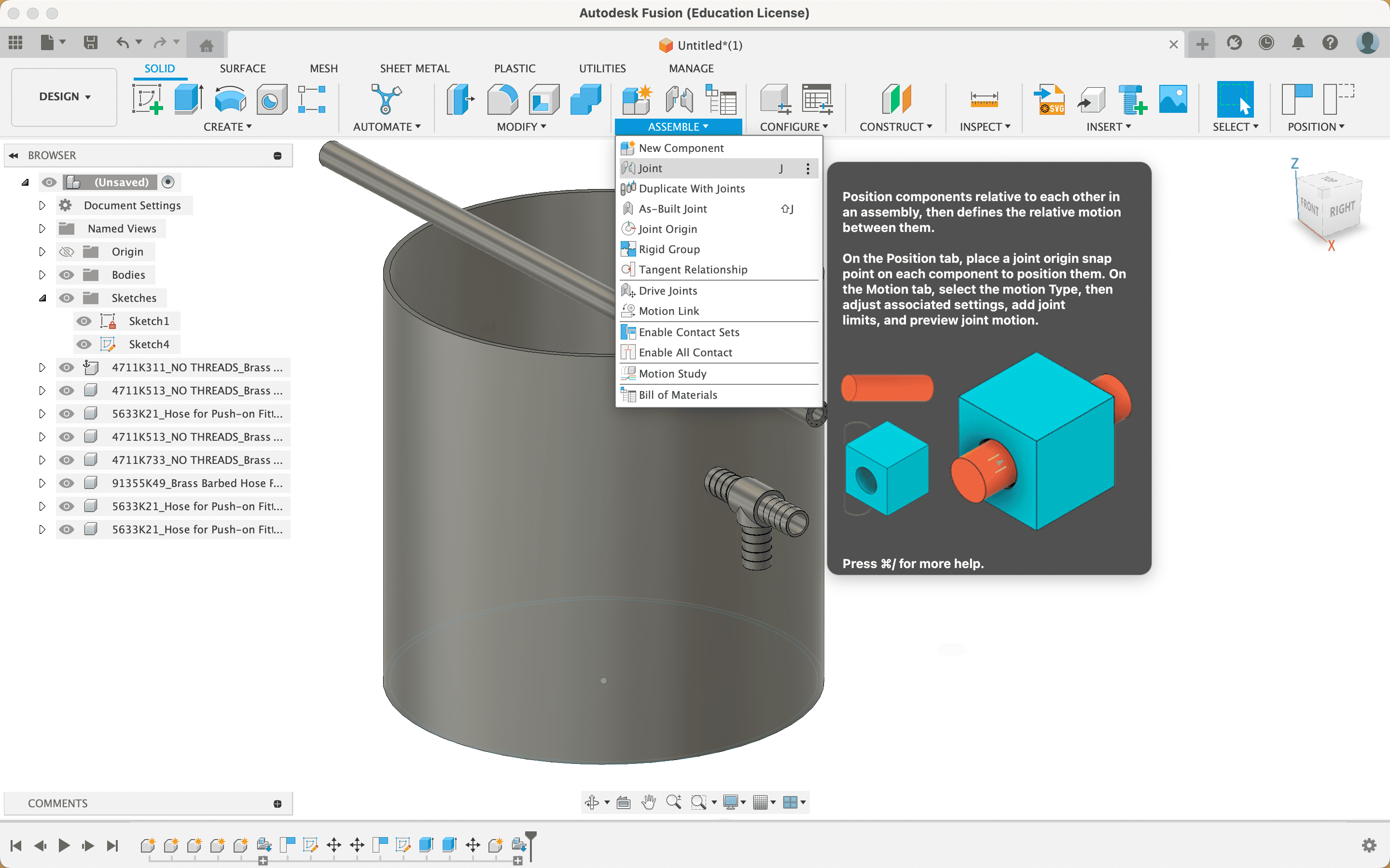
For this, I use the Assemble/Joint option in the top menu. This option asks me for the 2 areas or sections that will be joined.
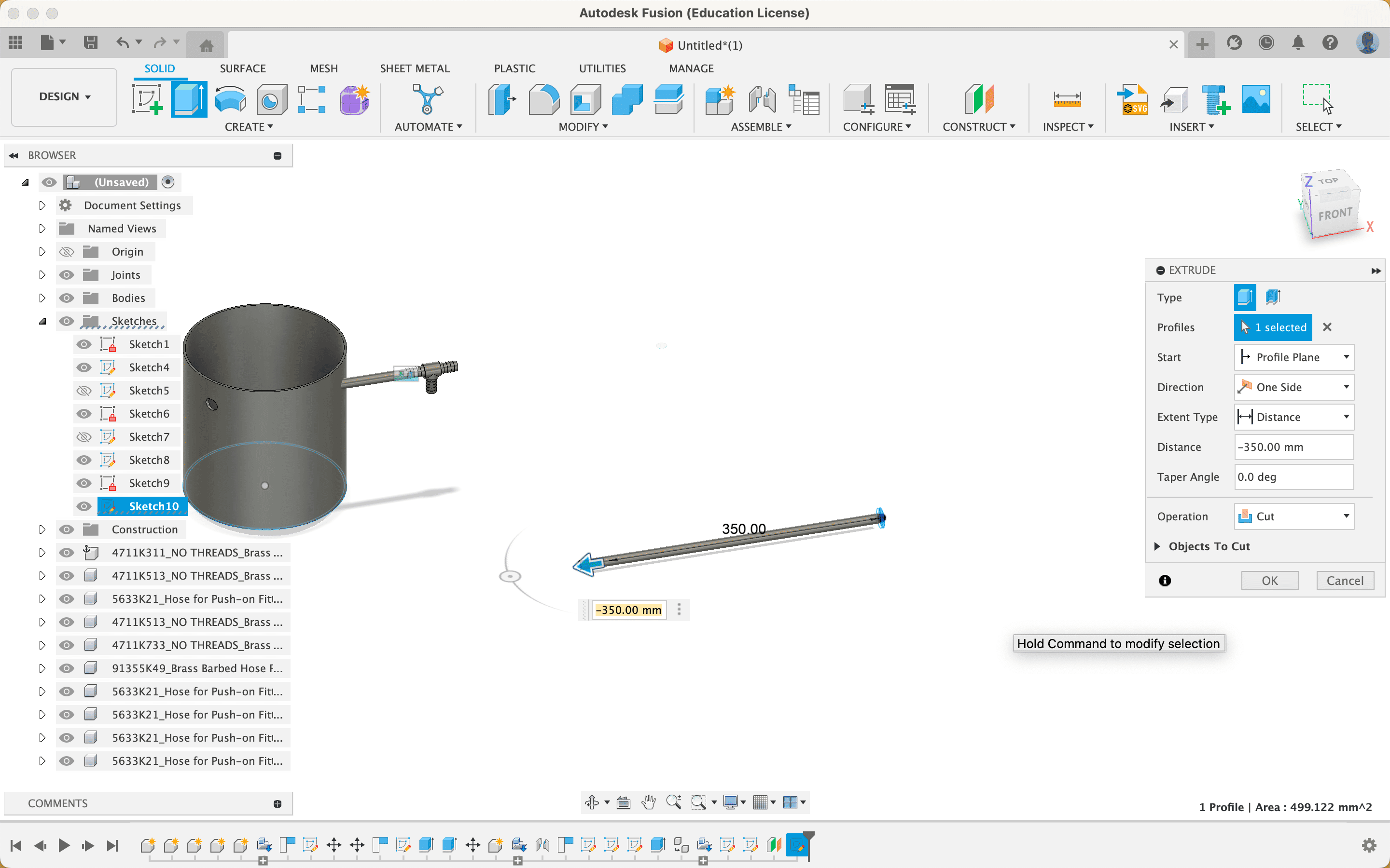
Since the inserted hose only has options of 5,10,15,20 feet and the one I need is different, I proceed to create a sketch in the hose area and then extrude it to the size I need.
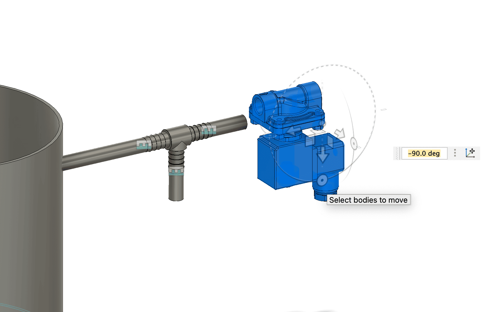
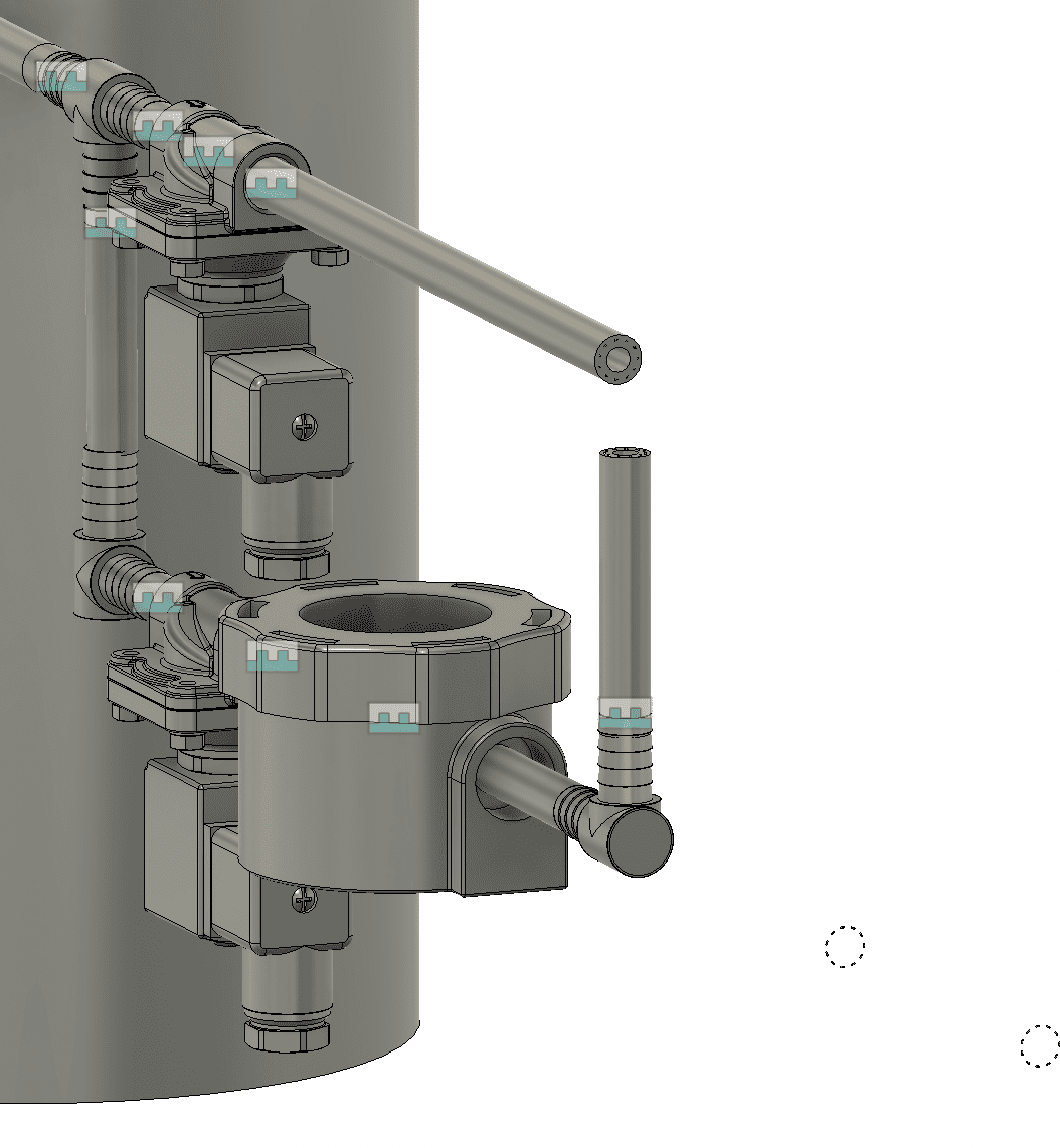
For the water leak detection system, I am going to work with 2 solenoid valves. The first (upper) will serve to close the water supply to a home or building, and will direct the fluid to a flow sensor. When this happens, the second solenoid valve (the one that is down) will be open.
After entering them, I proceed to join them with the same joint option.
When you do not want to measure water leaks, the operation of the solenoid valves will be reversed: the first will be open and the second will be closed.
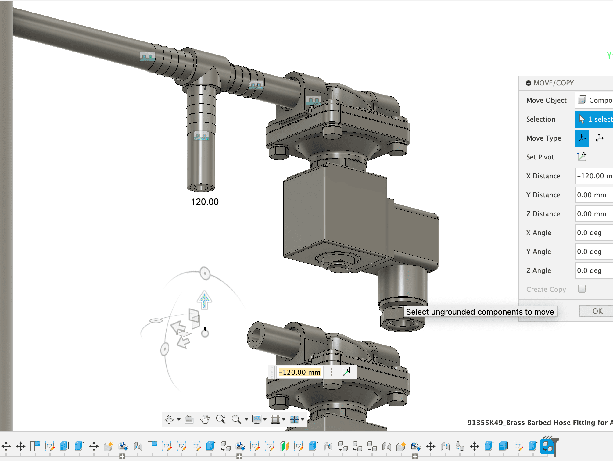
It is also necessary to rotate the inserted design, this was done with the move/rotate option, in the menu at the top
Then I add another solenoid valve and continue joining it to the system.
Now, I enter the water sensor. There are several types that I can use, I will be defining this later based on the tests I do as the weeks go by.
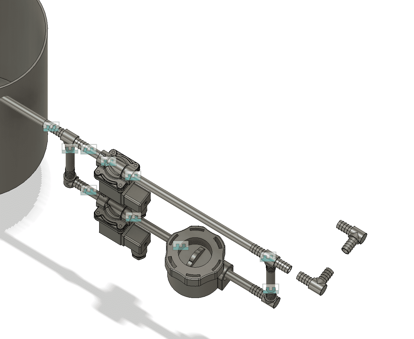
Then, I continue entering the connectors for the hoses. In this case, it will be for the hose that returns the water to the accumulation tank.
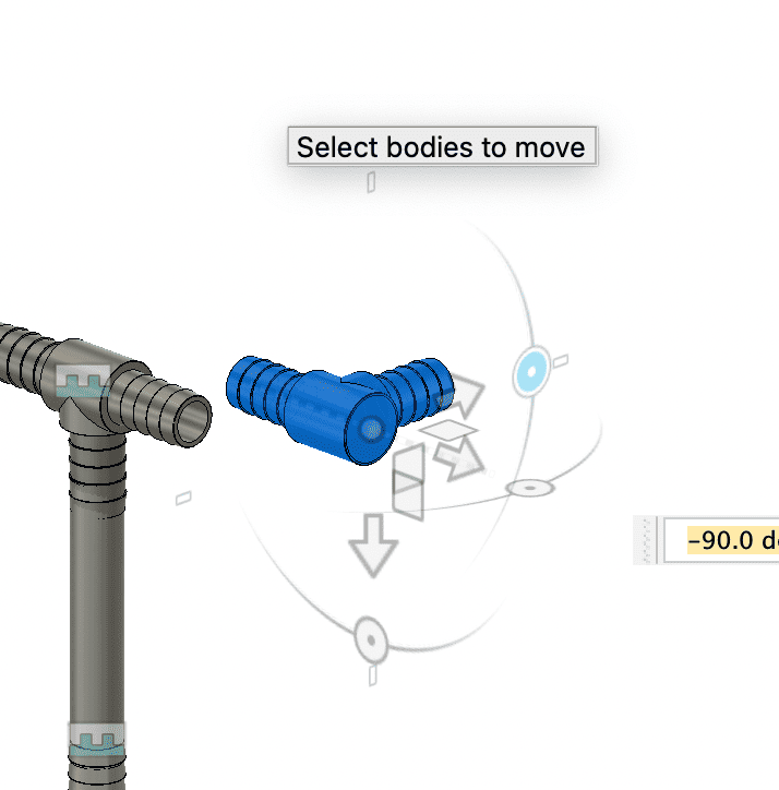
For this, I can continue copying and pasting the components I had entered, and just rotate them for my convenience.
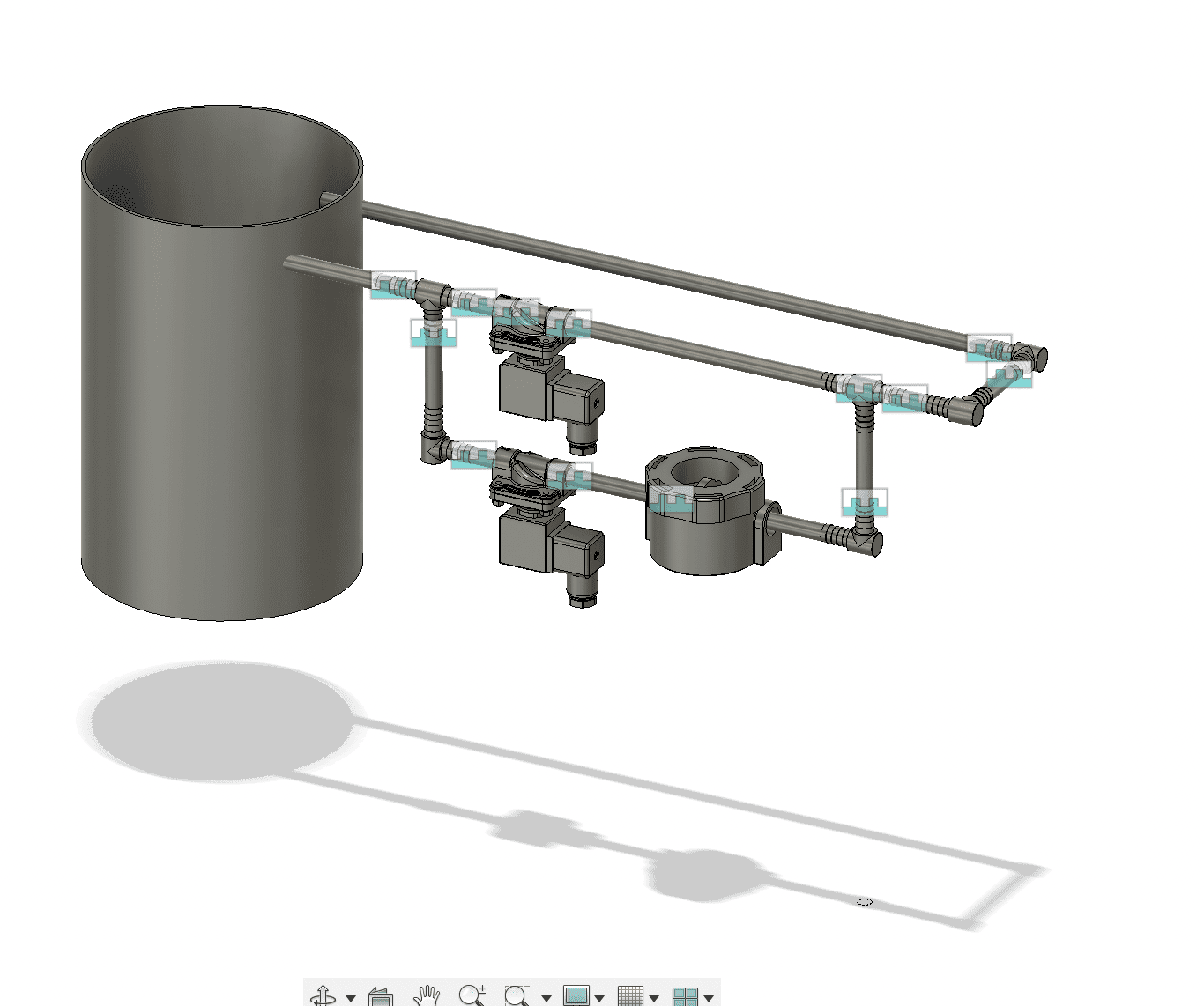
With this, I have the entire design of my preliminary water detection module ready. The marks that you see are the joints that I have made, they can be hidden or shown.
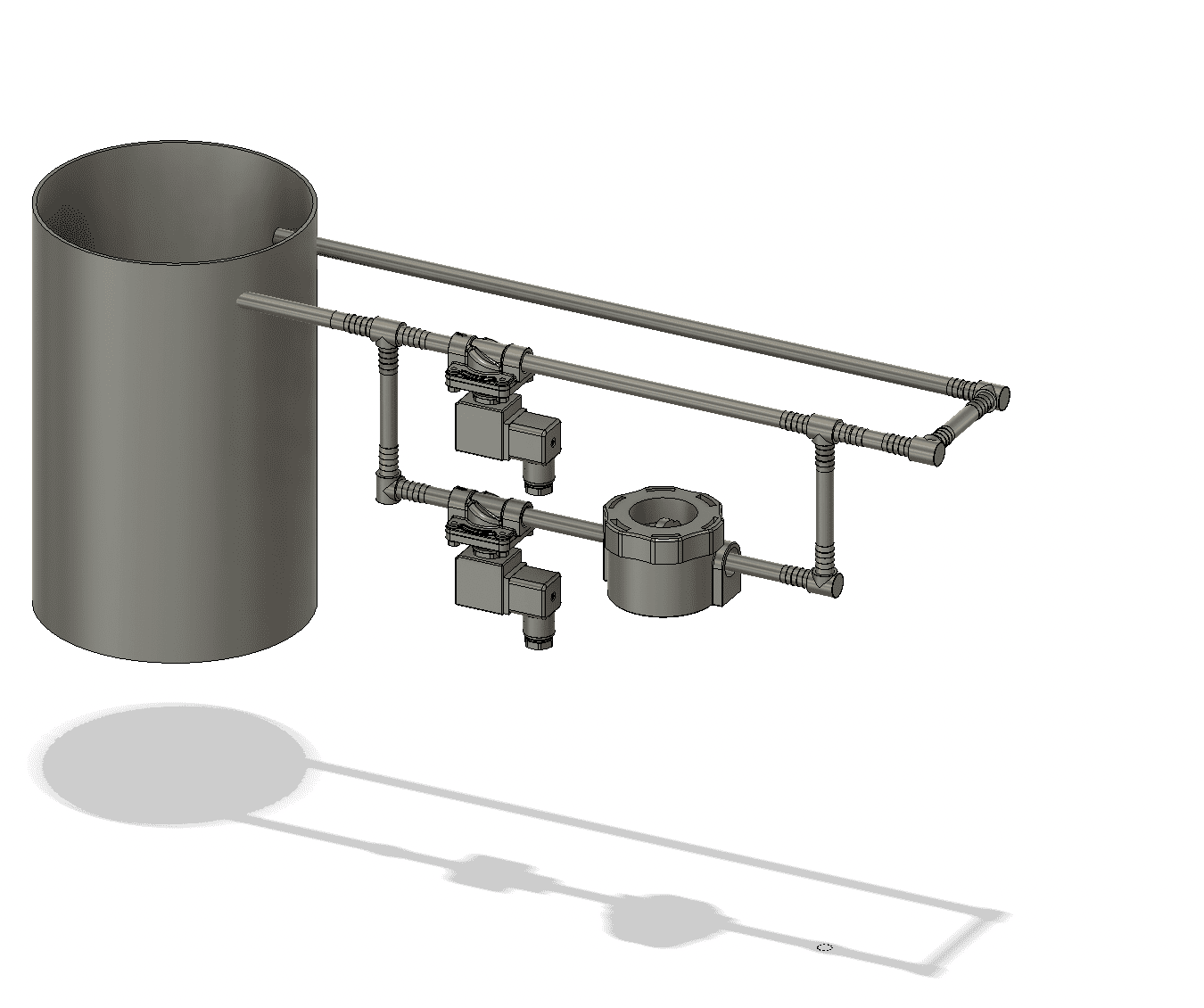
Finally, to be able to view it on the web page, use the fusion 360 web embed command.
Files: