Week 18 assignment: project development
Summary
This week task: Complete your final project tracking your progress.
Process
Create the project plan
The main tasks of my project are detailed in the following Gantt chart: First I started with a sketch of my project and with this I was able to make a list of the materials I will need. These materials were necessary to start the project, because as I progressed I realized that I needed other complementary ones.
Then, as the weeks progressed, I learned how to design and manufacture electronic boards. With this knowledge I began to design my project board and then solder all the necessary components. The previous weeks were quite helpful because all the boards I developed before helped me make the board for my final project.
Then I started programming my board. For this week, I have already managed to program the solenoids, the electric pump and the flow sensor. I have done preliminary tests with Wi-Fi communication using the Blynk app and I carried out the full integration of all the wiring with all the components this week as well.
Designing and printing in 3D is something that is being transversal to the project because every week I need to change some design or add another one. In two weeks I will be doing the final tests of the project to document in slide and video.
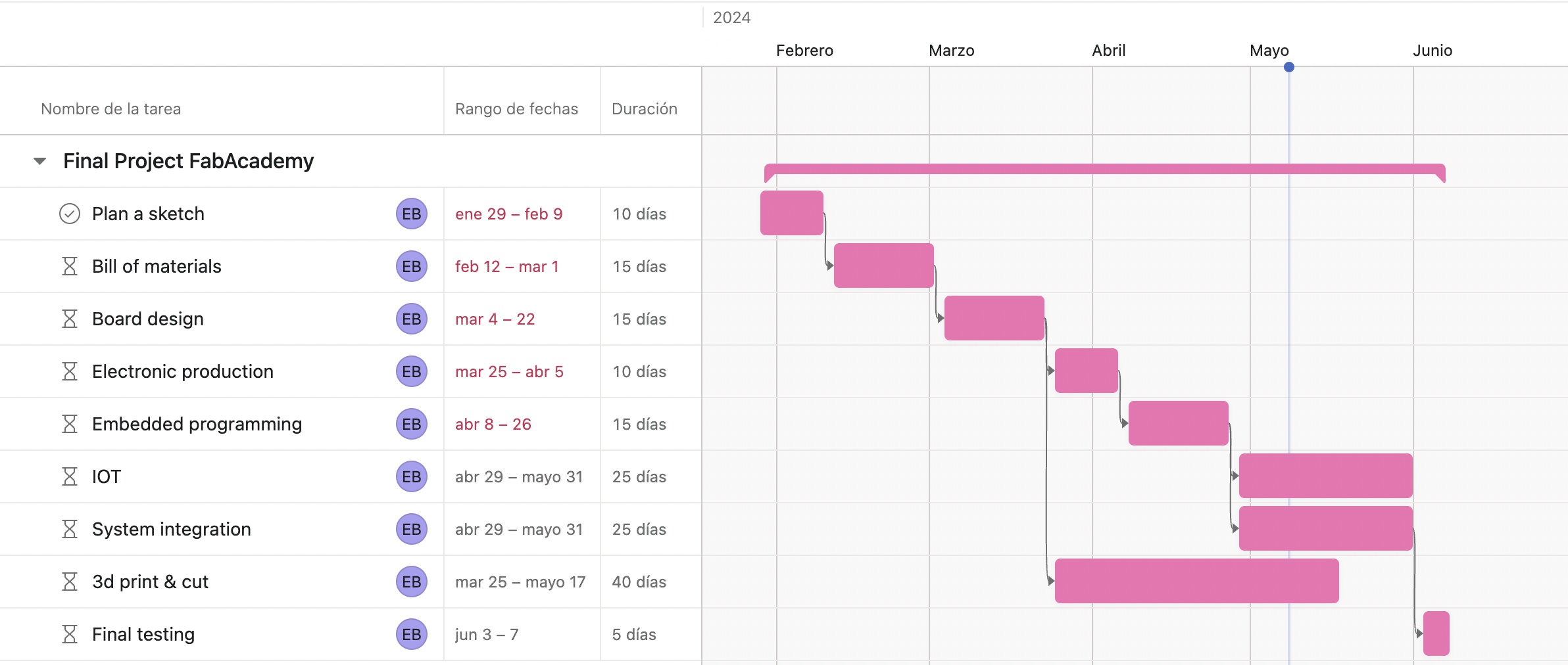
So far I have completed almost all the tasks in my Gantt chart and I am in the system integration part, having finished this week with the wiring and total assembly.
I still have to do the total electronic tests and verify that all the components work correctly, since until now I have only tested them one by one with satisfactory results.
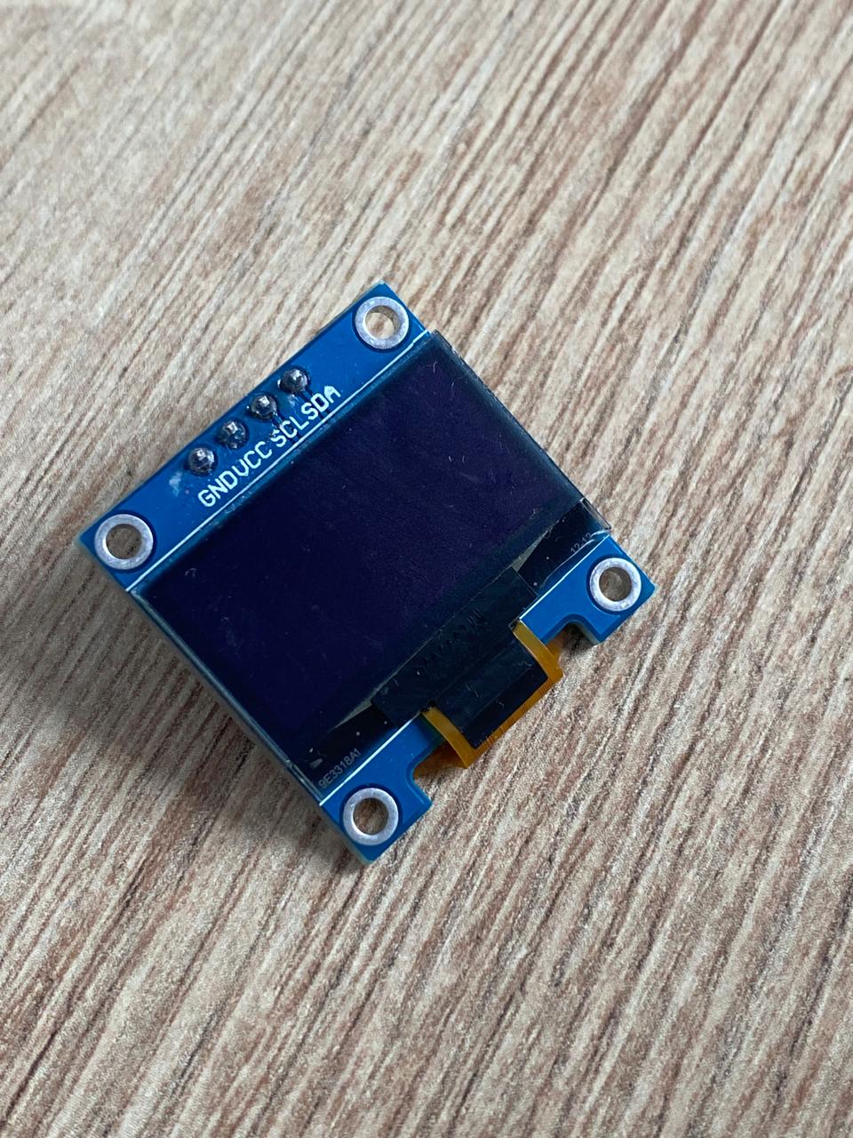
At the beginning of this week, my OLED screen was not working, but I changed it and the new one did work correctly. Later, talking to colleagues, they told me that since I had been moving the previous screen every week in various places, it was probably damaged, as it was a bit delicate.
I have learned how to program a flow sensor using an arduino library. Now I can use any other type of this sensor by changing the frequency of the pulses per liter.
Something quite valuable is the knowledge acquired to manufacture a board from scratch, as well as learning to design and solder SMD components.
Finally, I was able to find out and learn how to use the wifi communication of the xiao seeeduino esp32c3 and the possibilities to integrate projects. It is a very valuable IoT tool that I am sure will be used more in homes and businesses over the years.
Project development
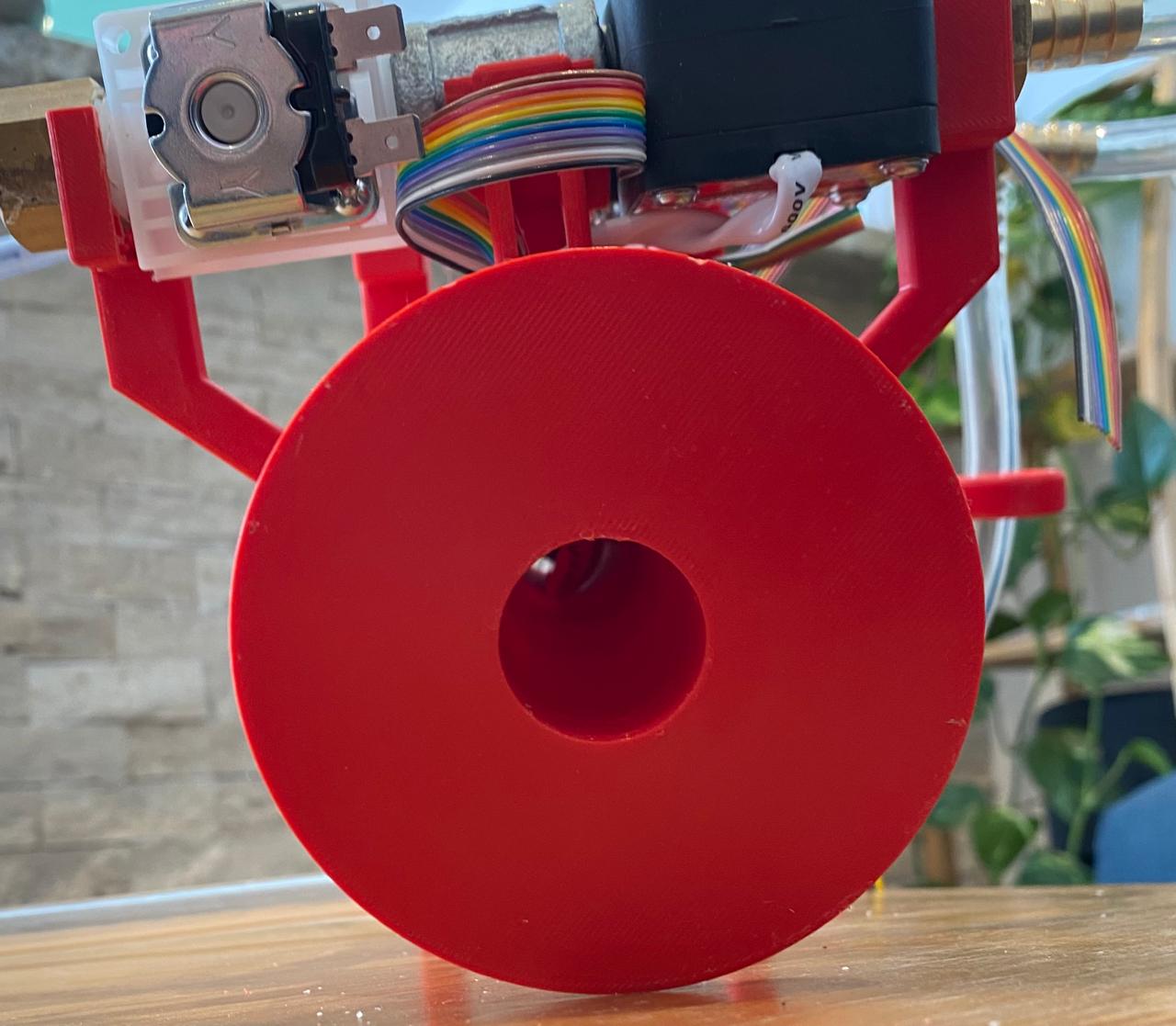
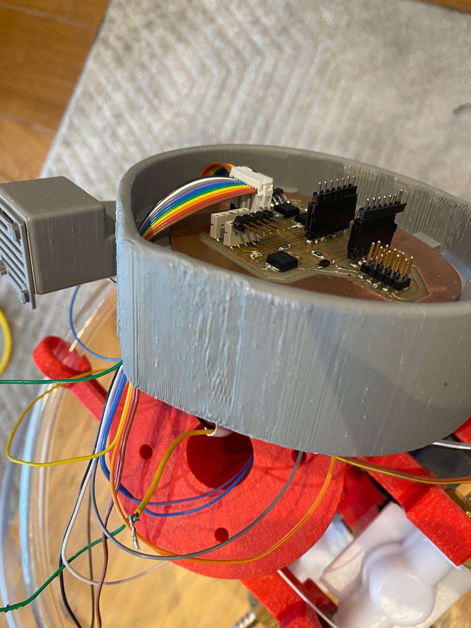
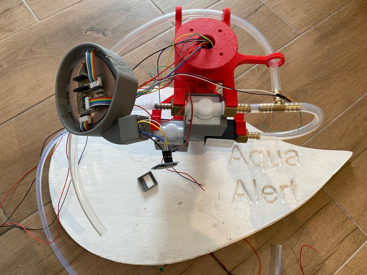
I also dedicate this week to integrating my entire project. I will use the compartments that I have created in the 3d prints of my designs to carry the wiring of all the electronic components to my electronic board and also to the 12v source with which it will be energized.
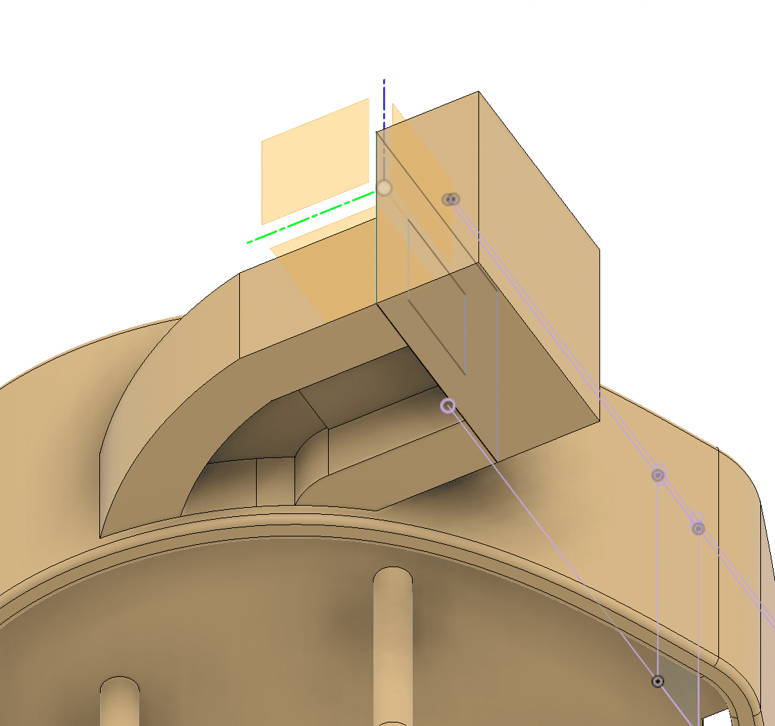
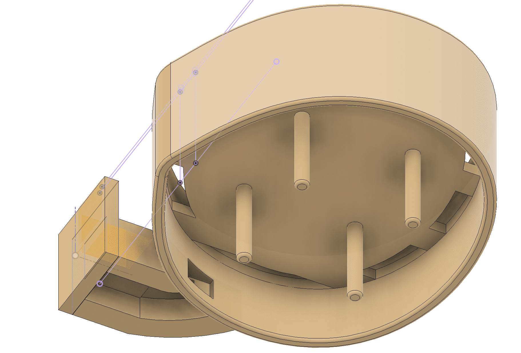
I have taken advantage of the same base to carry all the wiring through internal compartments and thus integrate the entire work module. Firstly, the component support was made with a hole in the center through which the entire cable branch passes.
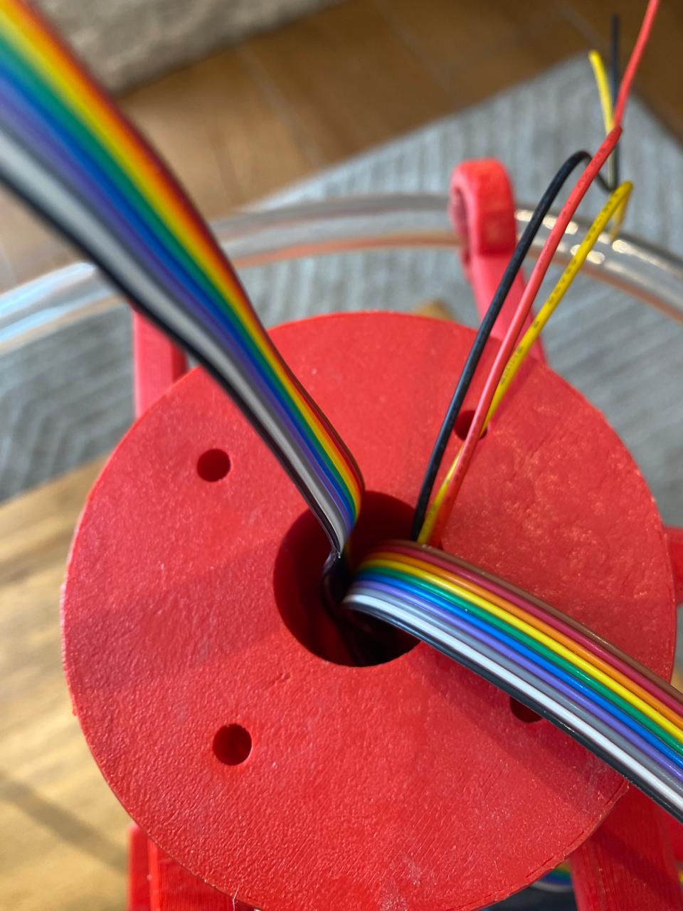
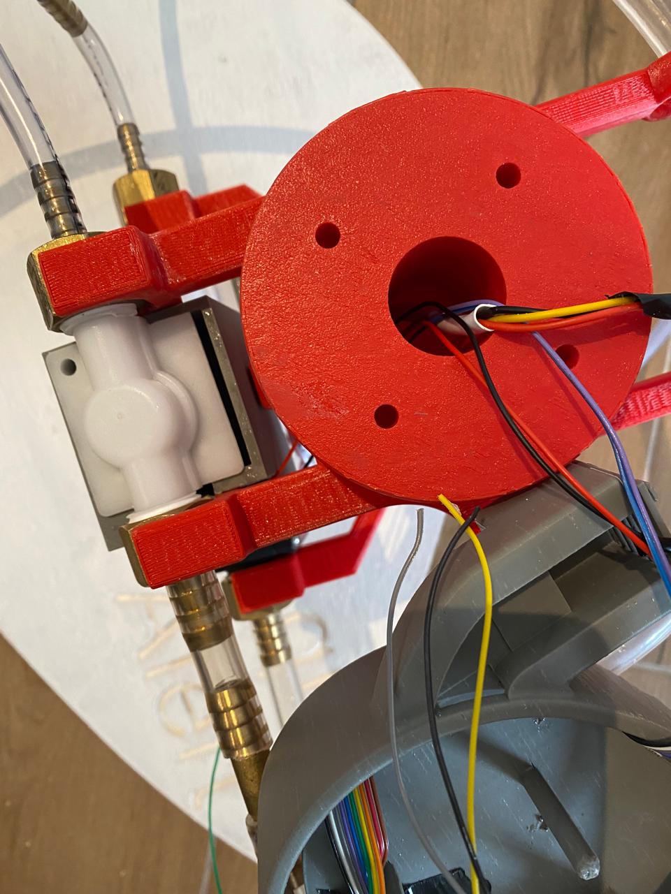
The cables that pass through here are the following:
- 12v positive and negative cables = 2 cables.
- Signal, positive 5v and negative cable for the flow sensor = 3 cables.
- Positive 12v and negative cables for each of the 2 solenoid valves = 4 cables.
- Positive 12v and negative cables for the electric pump inside the water tank = 2 cables.
- Positive 5v, negative, SDA, SLA cables for the OLED screen = 4 cables.
Total of cables: 15.
Passing the cables through here was a little complicated due to the little room for maneuver.
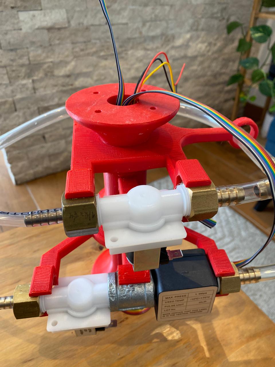
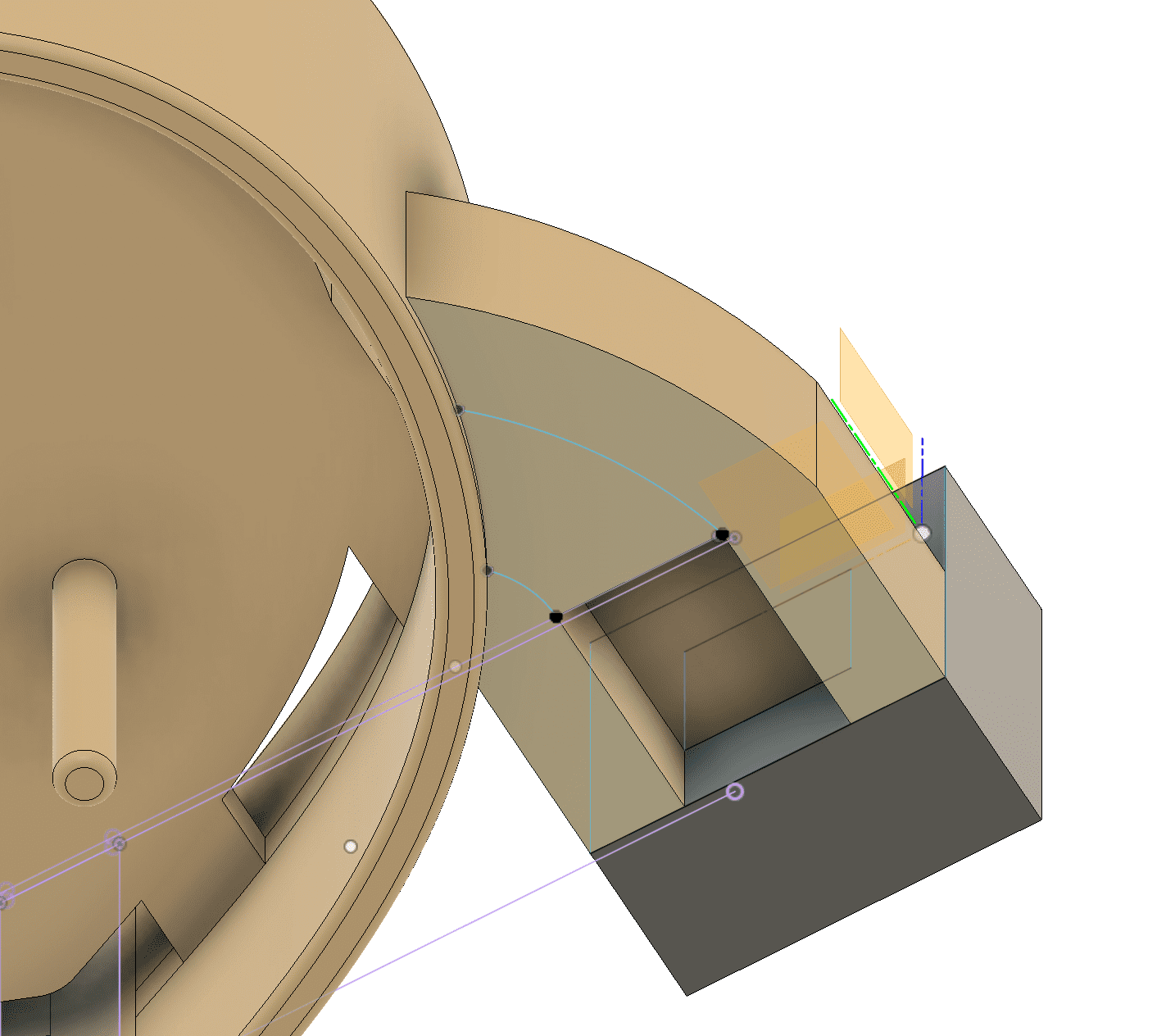
Then, so that the cables can reach the electronic board I had to design certain holes in the base where the board rests so that the wiring can pass through there.
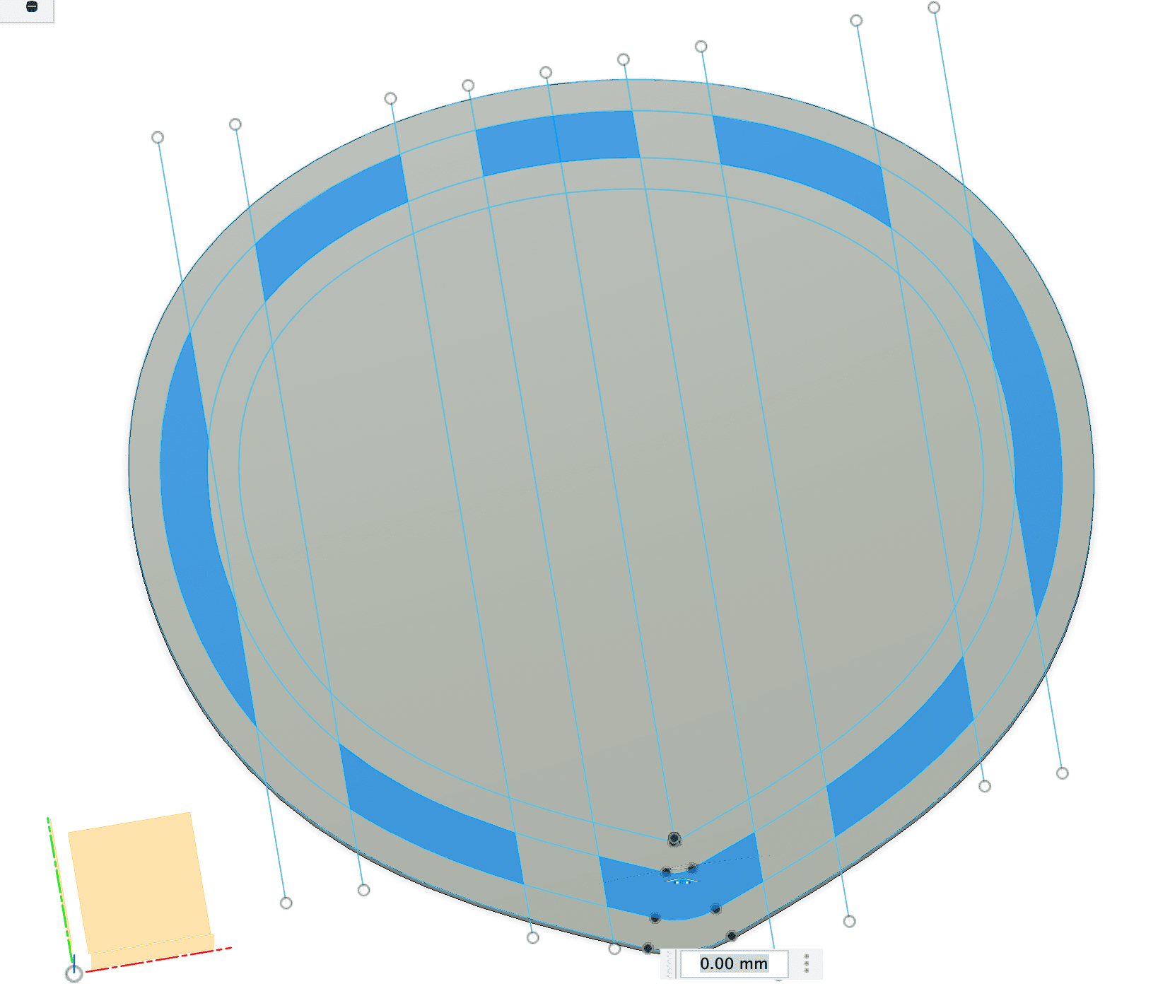
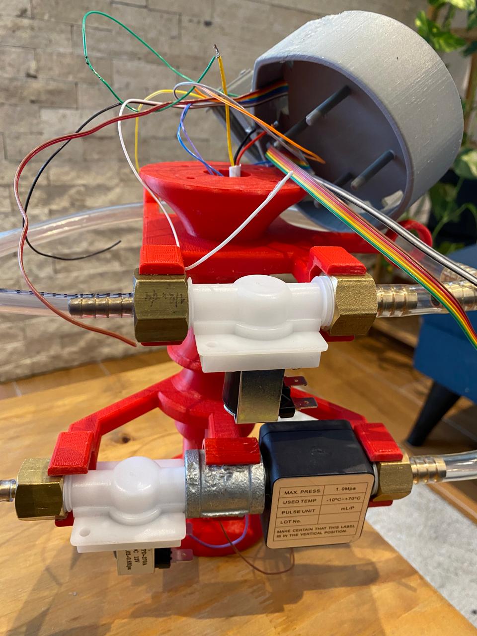
Also, I considered the wiring that the OLED screen needs. 4 cables must pass through this space that will energize and make I2C communication with the seeeduino and the OLED.
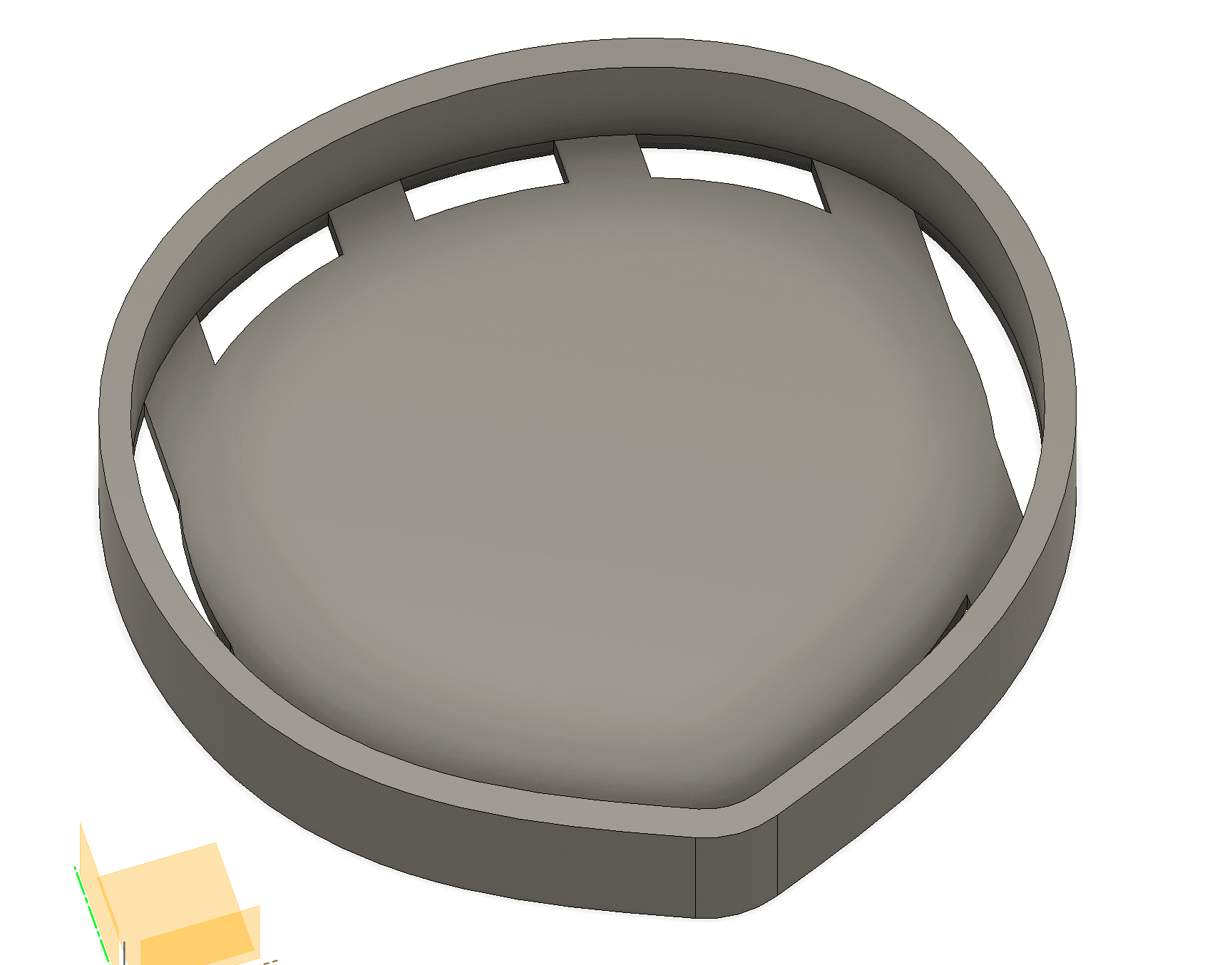
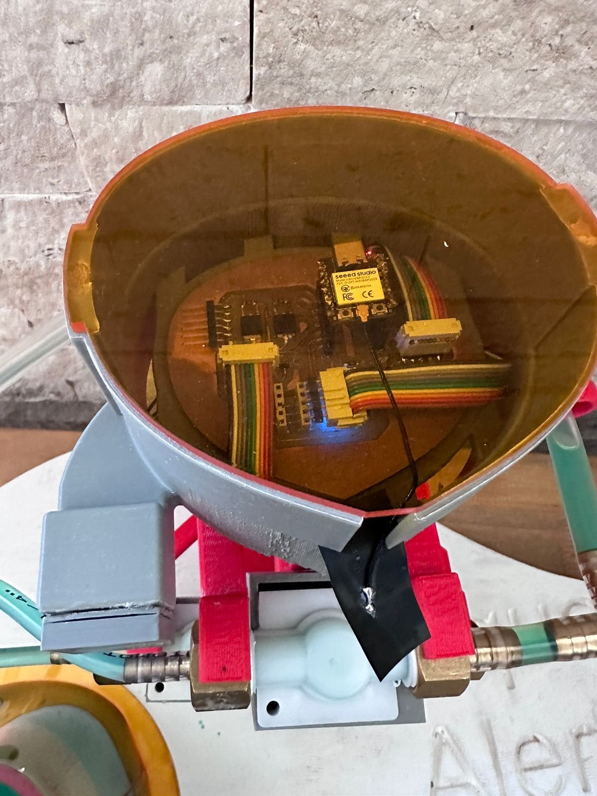
The design of where the OLED screen will be installed was considered so that it is together with the base of the electronic board.
This entire base where the electronic board and the OLED screen is held can be easily removed and inserted, so that the wiring is easy to do and without moving the cables so much.
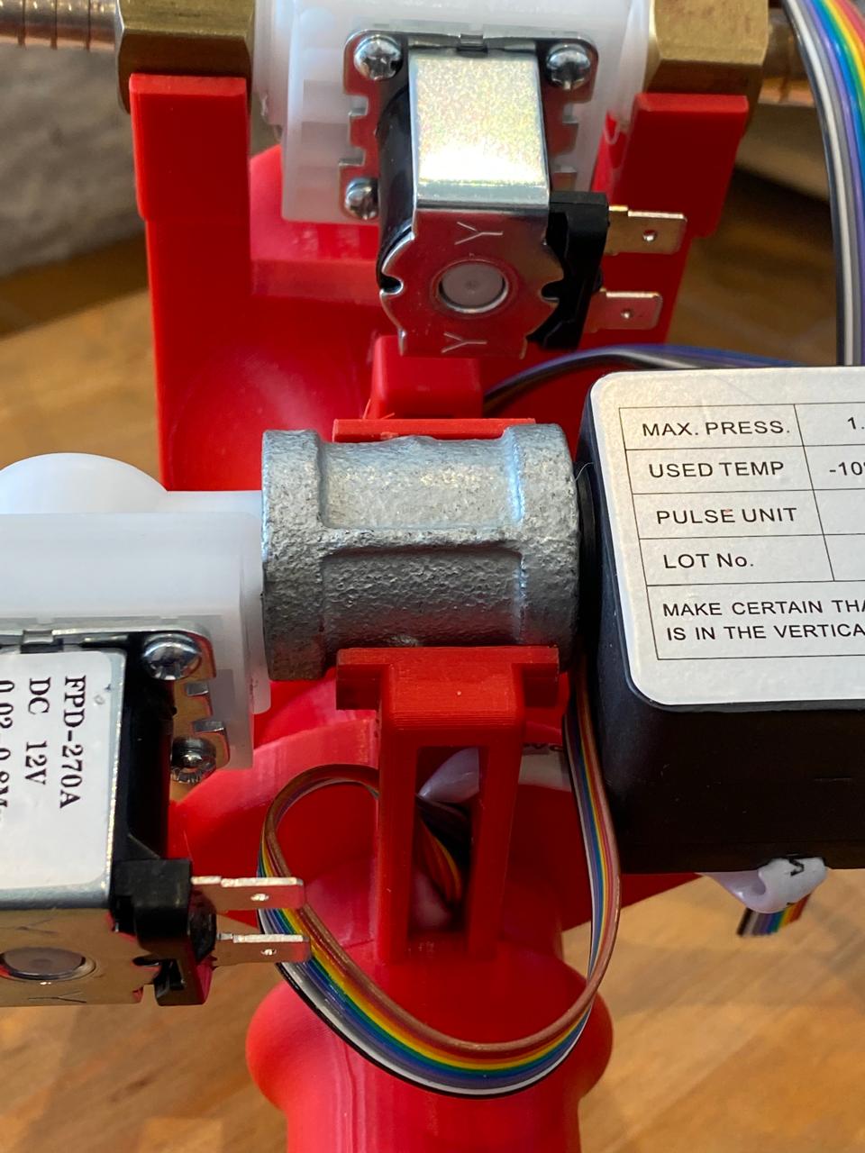
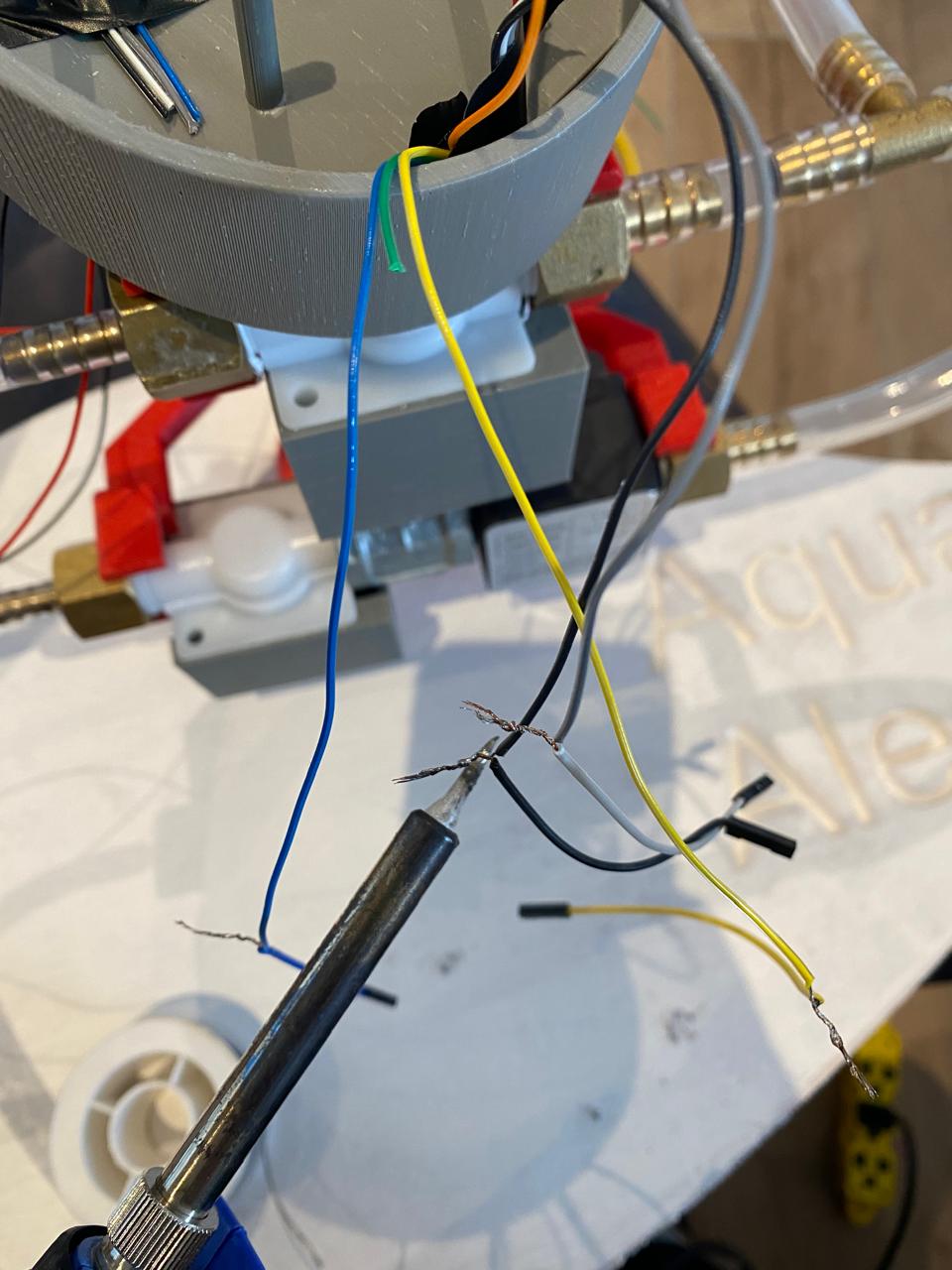
Try as much as possible not to have to cut any wires, but when required, solder the joint of those wires with tin filament and use a heat shrinkable coating.
Finally, all the cables are connected to the electronic board.

In addition, the connections of the 2 cables of the solenoid valves were covered with custom covers.


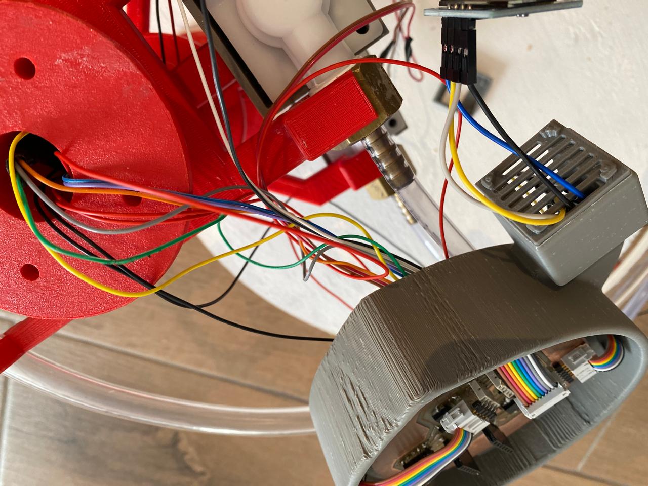
Finally, the electronic board is covered with an acrylic protector in case a few drops of water fall, which could affect it.
Files:
Total design f3z
Total design stl
Total base f3d
Total base stl