Week 16 assignment: wildcard week!
Summary
Week objective: Design and produce something with a digital process not covered in another assignment
Process
For this assignment I will be using the plasma cutter. The first step was to make the design in the fusion 360 software. For this project I made a sign for bicycles indicating the parking place.
Safty first
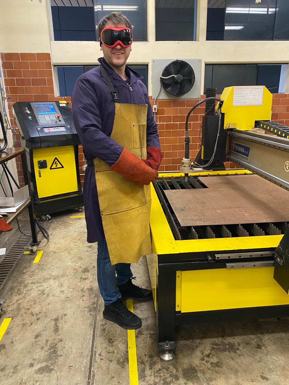
When using a plasma cutter, it's essential to wear appropriate personal protective equipment (PPE) such as an auto-darkening welding helmet, rated safety glasses, flame-resistant clothing, heavy-duty leather welding gloves, steel-toed boots and earplugs or earmuffs. Also ir is important to ensure the work area has adequate ventilation.
Design
In the following images you can see the design process:
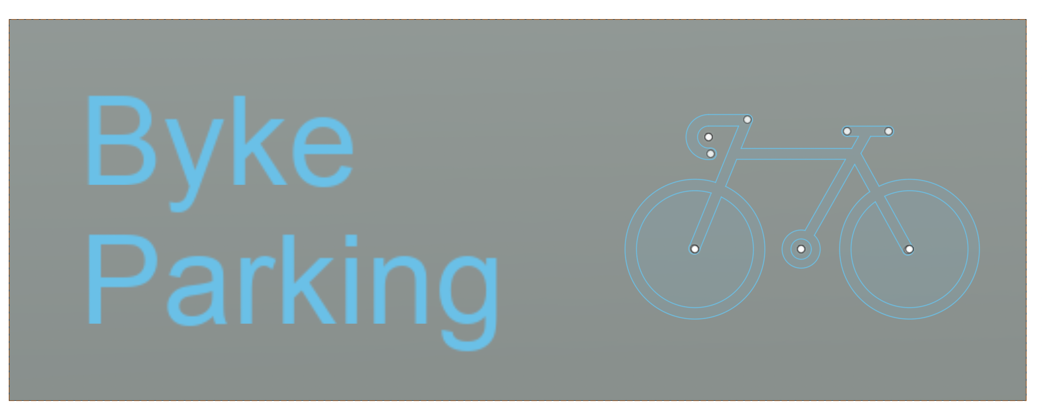
I start with the design by drawing the shape of a bicycle and another sketch for the letters
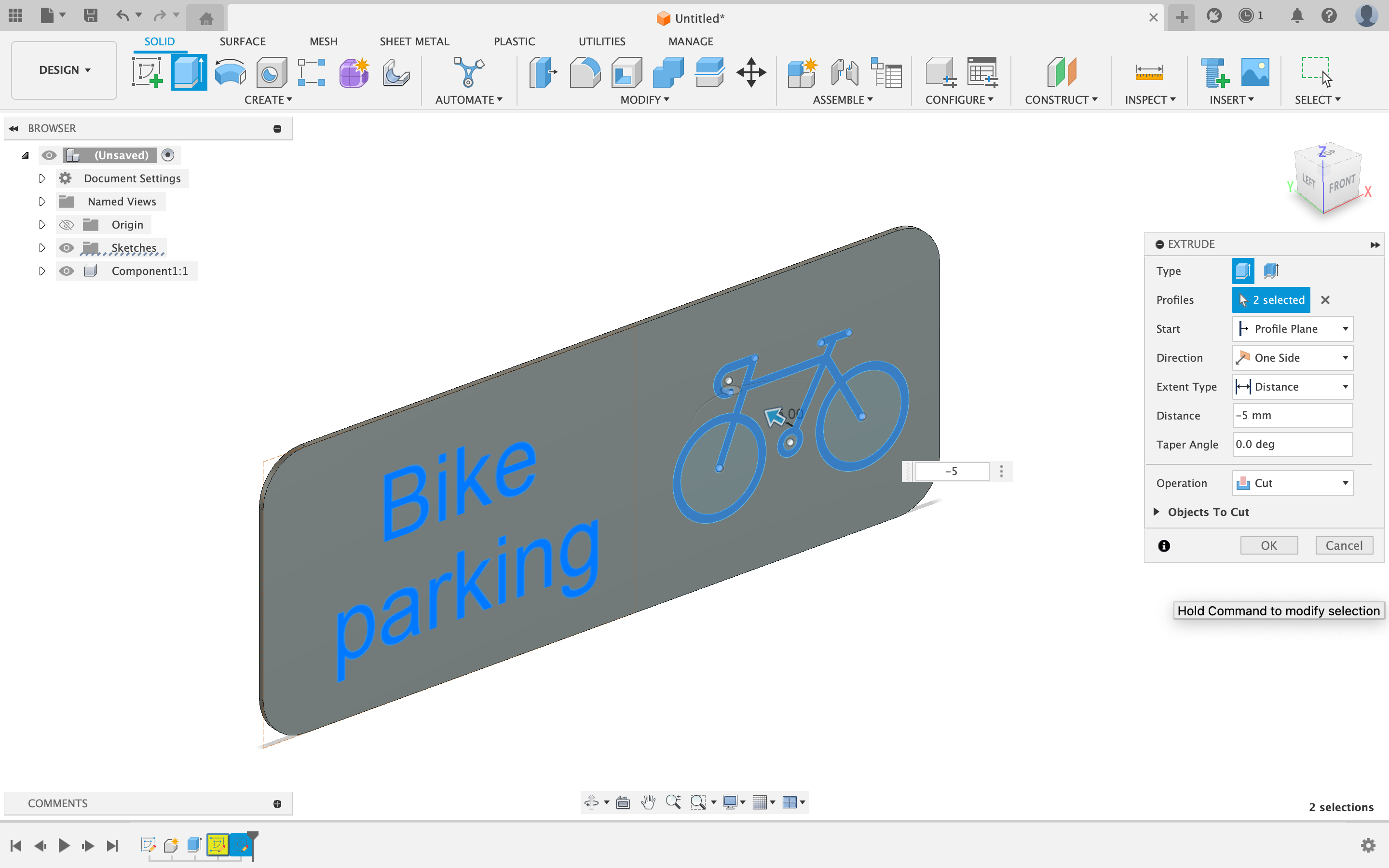

Then, I create a sketch that will be the one that I will export in dxf to generate the G code in the plasma cutter software.
I process this DXF file in the software and the result is the G code file that I will load later.
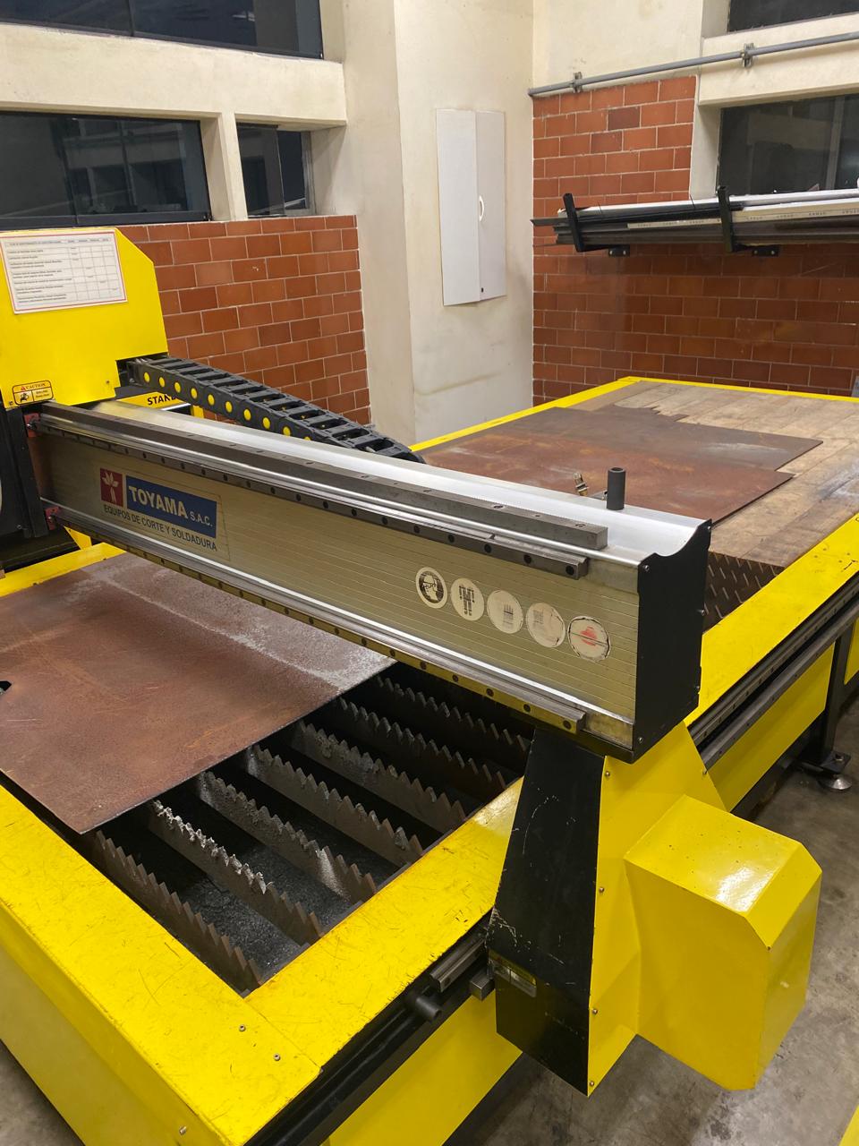
Plasma cutter Toyama
The plasma cutter is from the Toyama brand. The machine is capable of cutting various materials, including mild steel, stainless steel, and aluminum.
The speed can vary based on material type and thickness, as well as the power settings used.
The Plasma generates a temperature of 6000 to 8000 degrees Celsius, and the relationship between the nozzle amperage (40, 60, 80, 100 amps) and the advance (cutting speed) of a plasma cutter involves several key factors: Higher amperage nozzles (like 80 or 100 amps) generally allow for faster cutting speeds compared to lower amperage nozzles (like 40 or 60 amps) because higher amperage provides more power to cut through the material quickly.
For instance, a 100-amp nozzle can cut through thicker materials at a faster rate than a 40-amp nozzle, which is better suited for thinner materials.
Also, adequate gas or air pressure is necessary to maintain the cutting arc, especially at higher amperages. Insufficient pressure can slow down the cutting speed and affect cut quality. I used a speed of 2000 mm/min. I used the 40-Amp Nozzle that is suitable for thin materials, like the 2mm thickness of iron I used. It provides sufficient power to cut through the material efficiently while maintaining good cut quality.
In a plasma cutter, such as the Toyama, the following axes typically work:
X-Axis:
This axis moves horizontally from left to right or vice versa.
It is responsible for the lateral movements of the plasma torch during cutting.
Y-Axis:
This axis moves forward and backward.
It controls the forward and backward movements of the plasma torch.
Z-Axis:
This axis moves up and down.
It adjusts the height of the plasma torch relative to the material being cut, ensuring optimal cutting distance and quality.
G-code generation
Once the design is complete, the next step is to prepare the files for the plasma cutting machine. This involves exporting the design from the CAD software into a format compatible with the cutting software, commonly DXF (Drawing Exchange Format) or SVG (Scalable Vector Graphics). The exported file should retain all the necessary details, including the dimensions and scale of the parts. I used fusion 360 for the design and exported in DXF file.
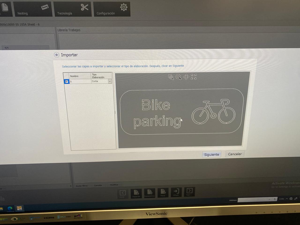
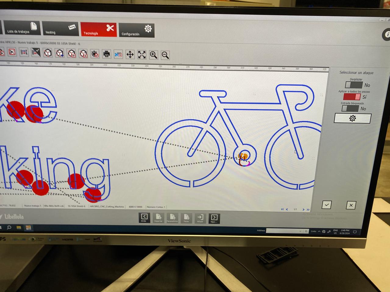
With the design files ready, the next step is to import them into the Libelula software, which is used to control the plasma cutter.
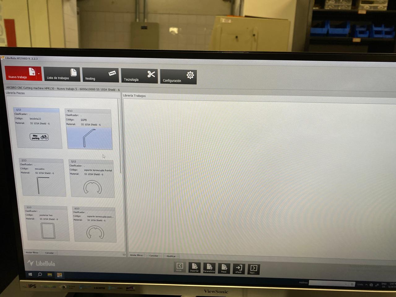
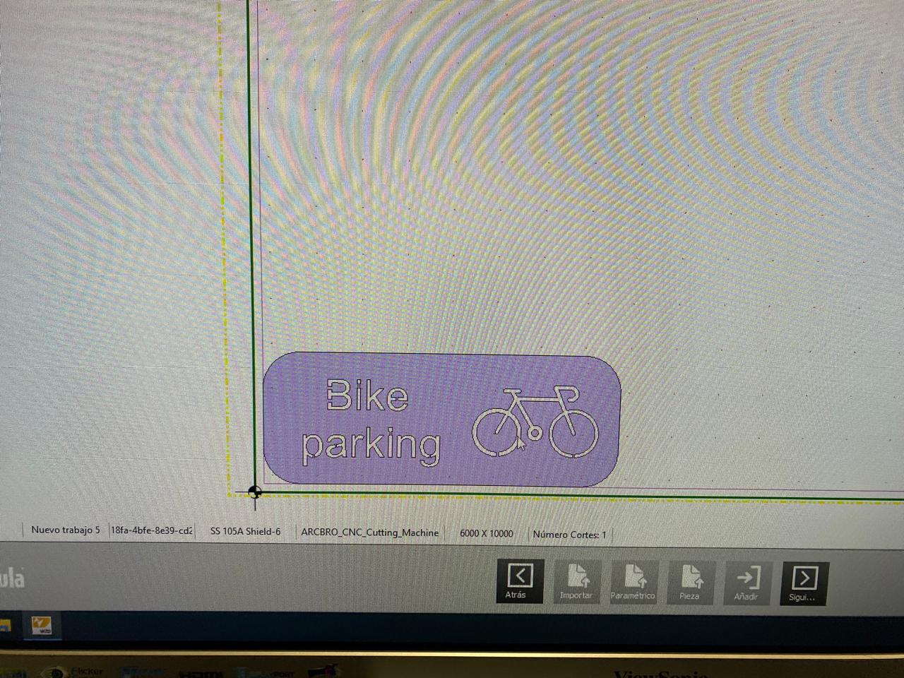
In Libelula, you will set up the cutting parameters, including the material type, thickness, and the specific cutting path. The software allows you to adjust the cutting speed, amperage, and gas pressure according to the requirements of the material and the desired cut quality.
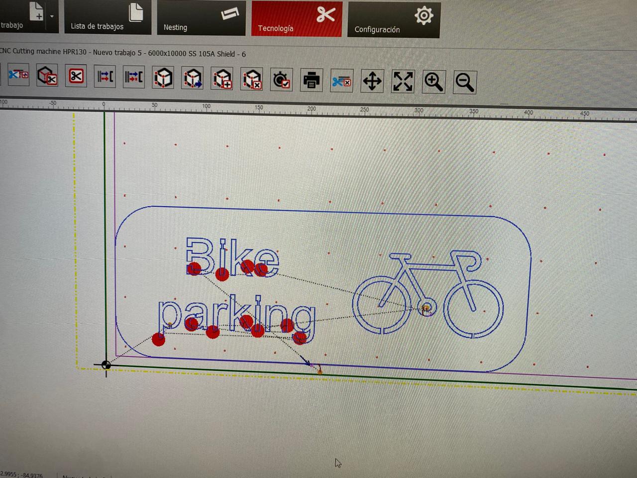
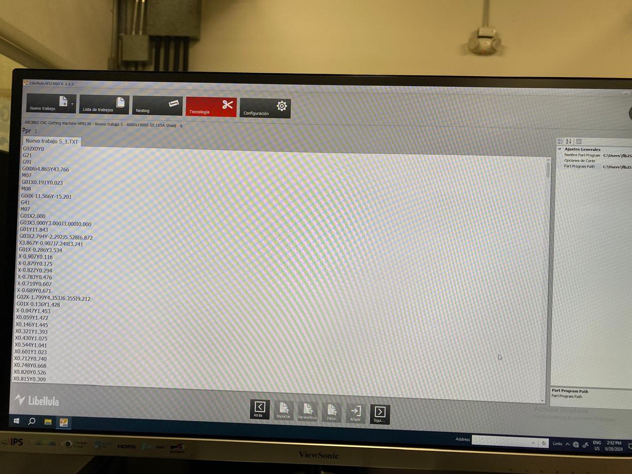
Once the parameters are defined, we proceed to generate the g code in a text file, save it in memory and load it into the laser cutting machine.
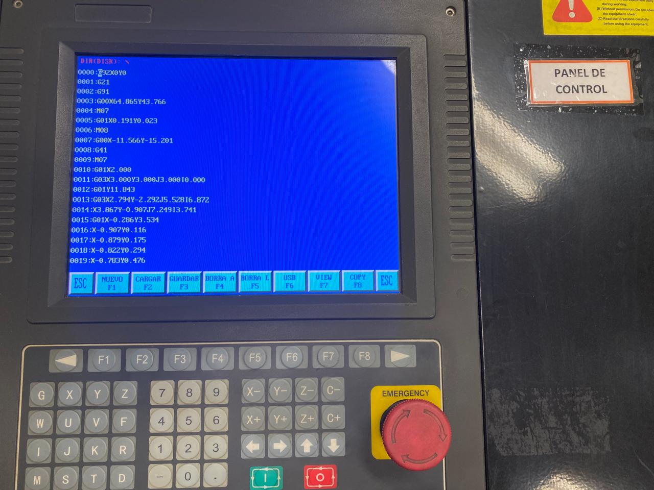
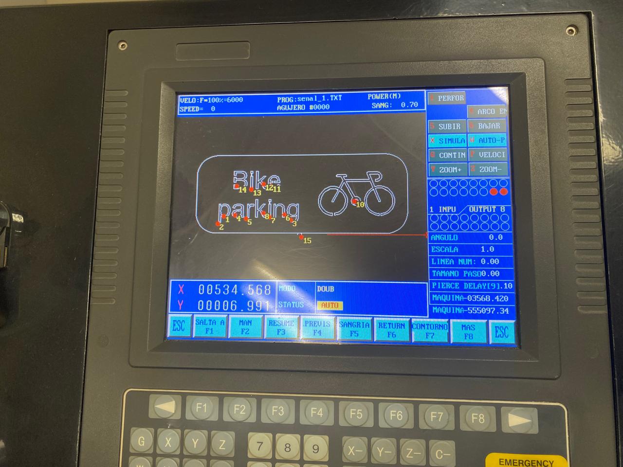
This is the panel where the previously generated G code is loaded.
Cutting with plasma
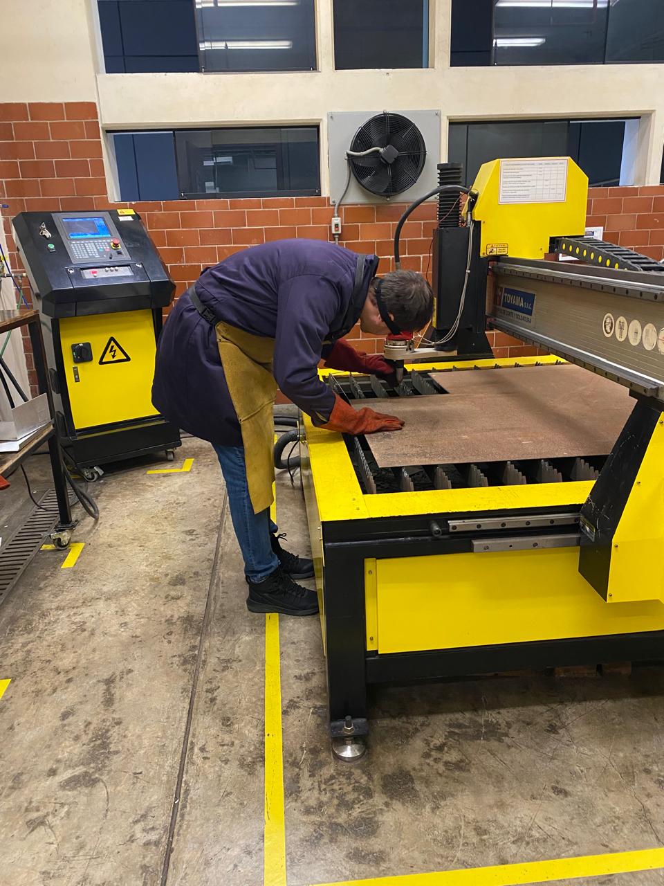
When the cutting begun, it is important to maintain a safe distance and use personal safety elements.

First, a simulation is made of how the cut would be made.
Then, the plasma cut begin with the configured parameters.
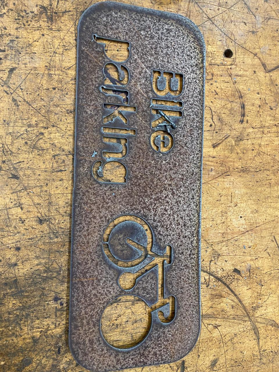
Finally, you have the cut poster. Prior to use, you must sand and perform some heat treatment to prevent it from rusting over time.
Files: