Final Project
Summary
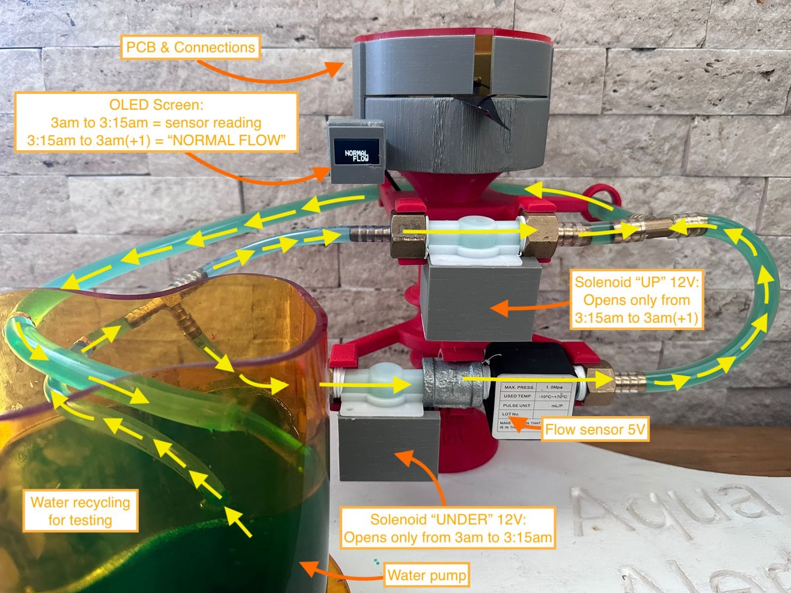
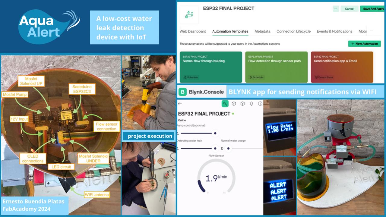
My final project consists on manufacturing a residential low-cost water leak detector. This idea is presented taking into account the waste of this resource due to failure of sanitary installations, connection pipes or simply due to a poorly closed water pipe. Until now, the design includes a water tank that would continuously recirculated the water thanks to a small submersible electric pump. There will be a water pipe that simulates the main network from which a facility is supplied (like a house or a building) and another small parallel network that will work only in the early morning hours.
In addition, it is contemplated to use 2 solenoid valves that will allow the gates to be closed or opened in the time range of 2 to 3am. During this period of time, the first valve will close and the second will open so that the liquid enters through the parallel network and passes through a highly precise hall-type flow sensor. After this hour, the valves are reversed, opening the first and closing the second, so that the water flows in its normal network.
The idea of operating the flow sensor only from 2 to 3am is proposed because during that time there is no regular water consumption, and what the sensor senses will correspond to a liquid leak. In addition, operating the sensor for one hour prolongs its useful life. The cost of implementing this system in a home network is around $100. In the next weeks, I will detail the materials I will need, calculating the exact cost. Finally, I will work with Iot by sending the information of the sensor to the cloud and creating alarms indicating if there is a water leak in a residence.

Process
This is a gantt chart indicating all the steps of my final project.
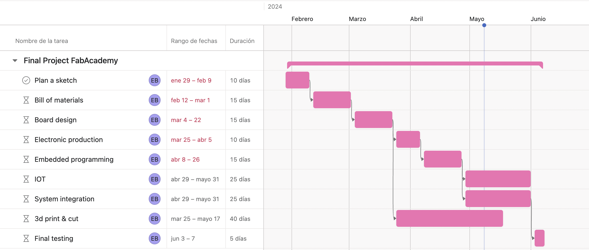
The list of materials are the following:
- 1 12v-electropump (it must drive a low flow rate, this will simulate a water leak).
- 2 12v-solenoid valves.
- 3 MOSFET (metal–oxide–semiconductor field-effect transistor) min 1.5A. With this I will be able to regulate the water flow with PWM and the opening or closing pulse of the valves. I will also need tin filament for soldering, resistors, LED diode, header pins, cables.
- 1 hall type flow sensor.
- 1 LED screen to show the flow variable.
- 5 linear meters of 1/2" transparent hoses.
- 6 1/2" hose to device adapters (will be tested by printing them and checking for leaks at the connections).
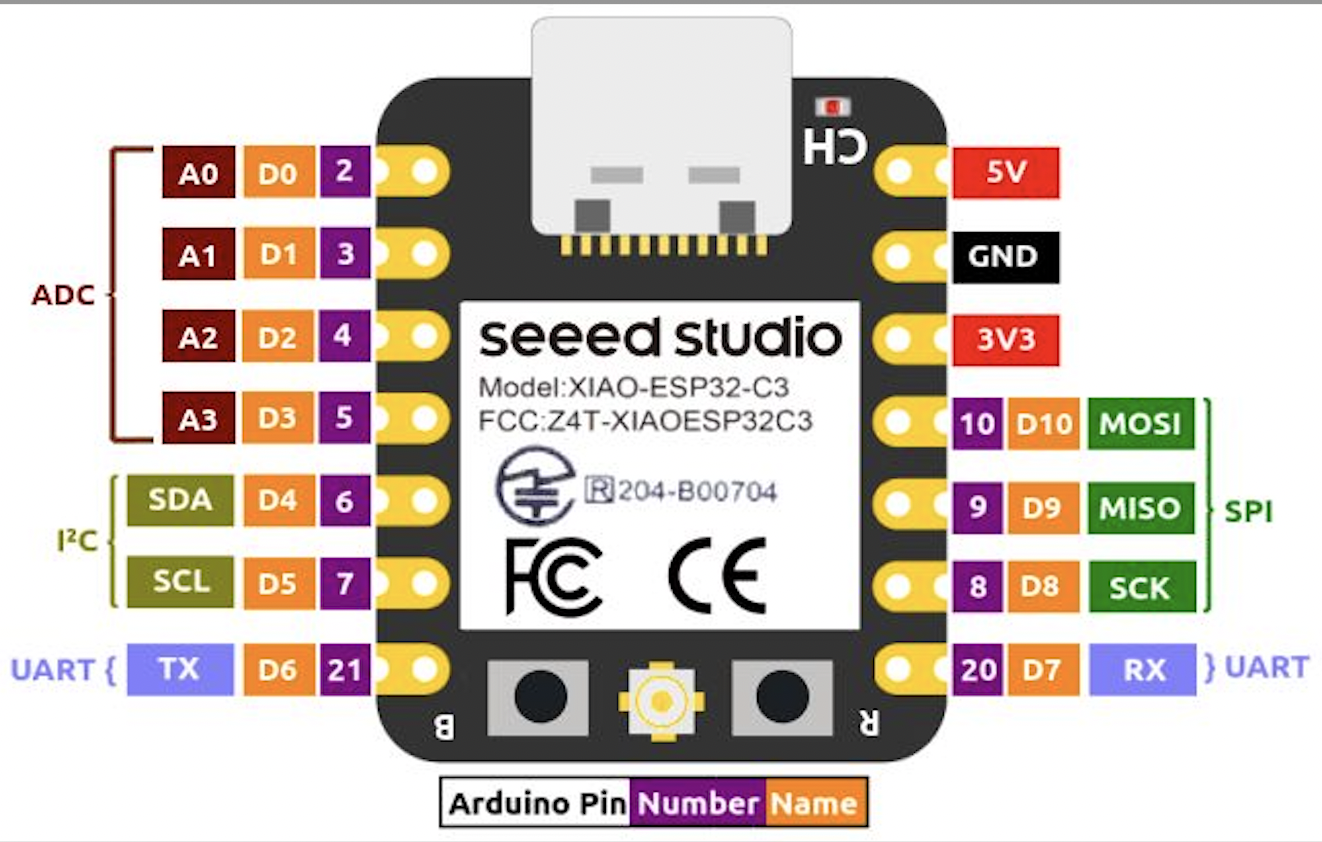
- 1 Seeed Studio XIAO ESP32C3 IoT mini development board.
- 0.25 square meters of acrylic to make the tank.
-Copper clad laminates for the manufacture of electronic boards.
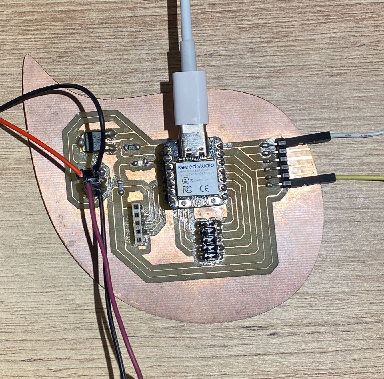
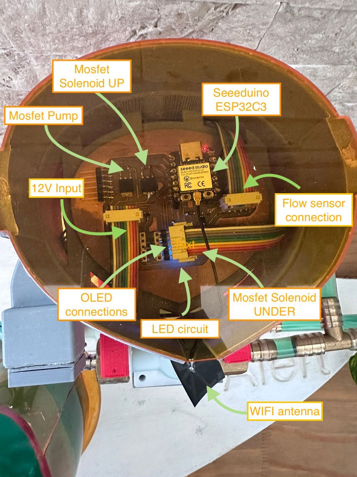
Continuing with the progress of the project, I have managed to design, manufacture and program a first version of the board by testing the components necessary for the final design. I already managed to obtain all the necessary components, and the final design of the board and its subsequent manufacturing and programming would be missing.
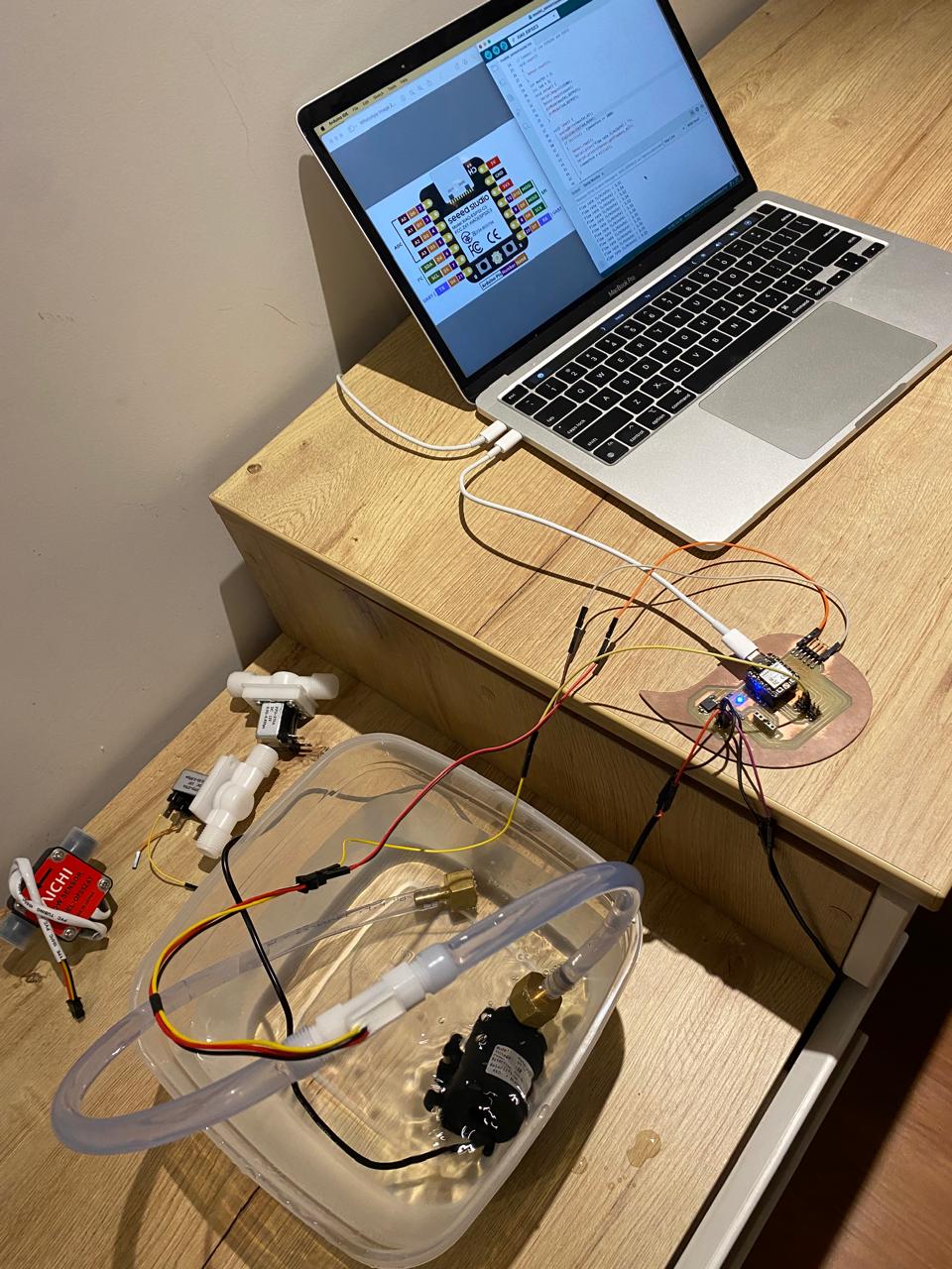
The processor I am using is a seeeduino ESP32-C3 that will allow me to use IoT to connect to a Wi-Fi signal and send my sensed variables to create alarms.
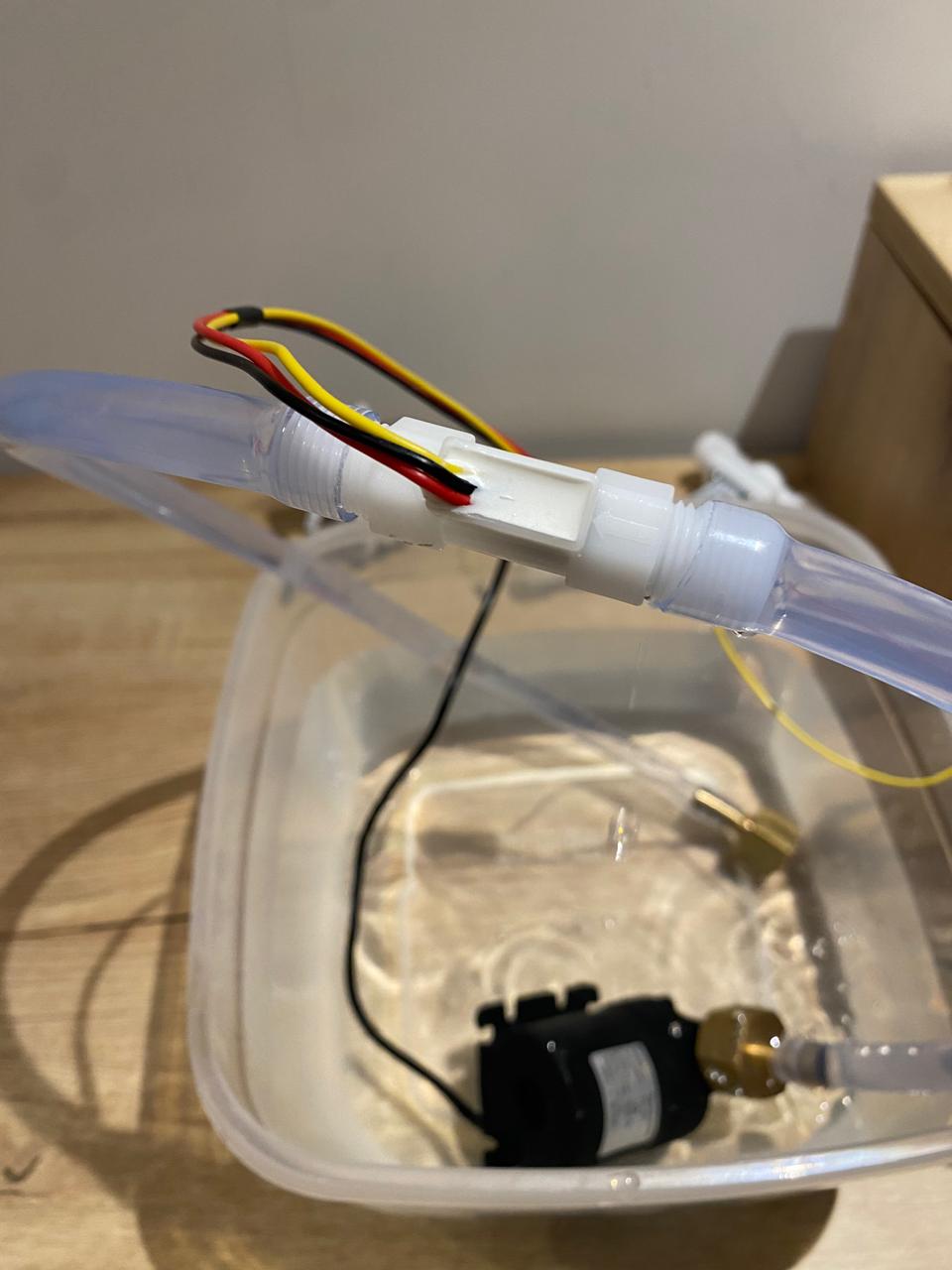
For this first stage, I have managed to make the 12v electric pump work and regulate the flow delivered, simulating a water leak. Likewise, I have managed to read the readings of a flow sensor and send them to the Arduino IDE serial monitor. The 12v are delivered by a separate source and it energizes a pin header so that the actuators are powered from there.
It is important to mention that the seeeduino ESP32-C3 works with 5v and does not deliver the 12v that these 3 components require, therefore I will be using a MOSFET for its control.
However, I will need to make another board where I can also control the opening and closing of the solenoid valves. For this, I will add 2 more MOSFETs to the analog pins of the seeeduino ESP32C-2. In this test, my board only has one MOSFET which I used to test the two solenoids as well as the electropump.
The video below shows the correct operation using the MOSFET of the current board. You have to be a little careful to hear the sound of the solenoid coil energizing
I will also add a voltage regulator from my supply that is 12 volts to 5 volts for the seeeduino, since it will not be connected to the computer when it is running and therefore will not be energized. This board does not has a 12v-5v regulator as I dont need it right now.
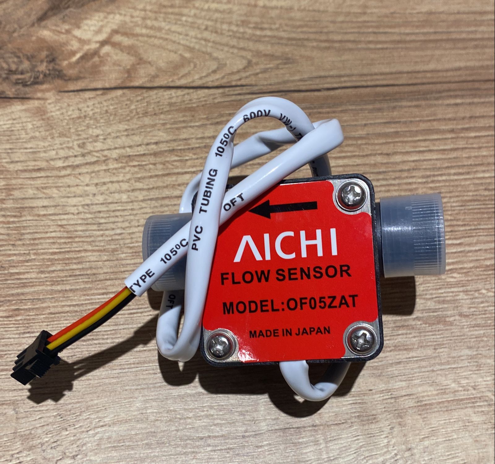
The flow sensor that I am using at the moment does not have the minimum sensitivity that I need, so I have purchased another much more sensitive sensor that allows me to measure 5 liters/hour or 0.08 liters/minute according to its datasheet. With this sensor, I will be able to take lower flow readings that simulate a water leak in a residence.
Mid may update
As of this date, I have a little more than 3 weeks to prepare my presentation of my final project. In line with the progress of the weekly assignments, I have managed to make good progress with my final project as it is shown below.
PCB design and manufacturing
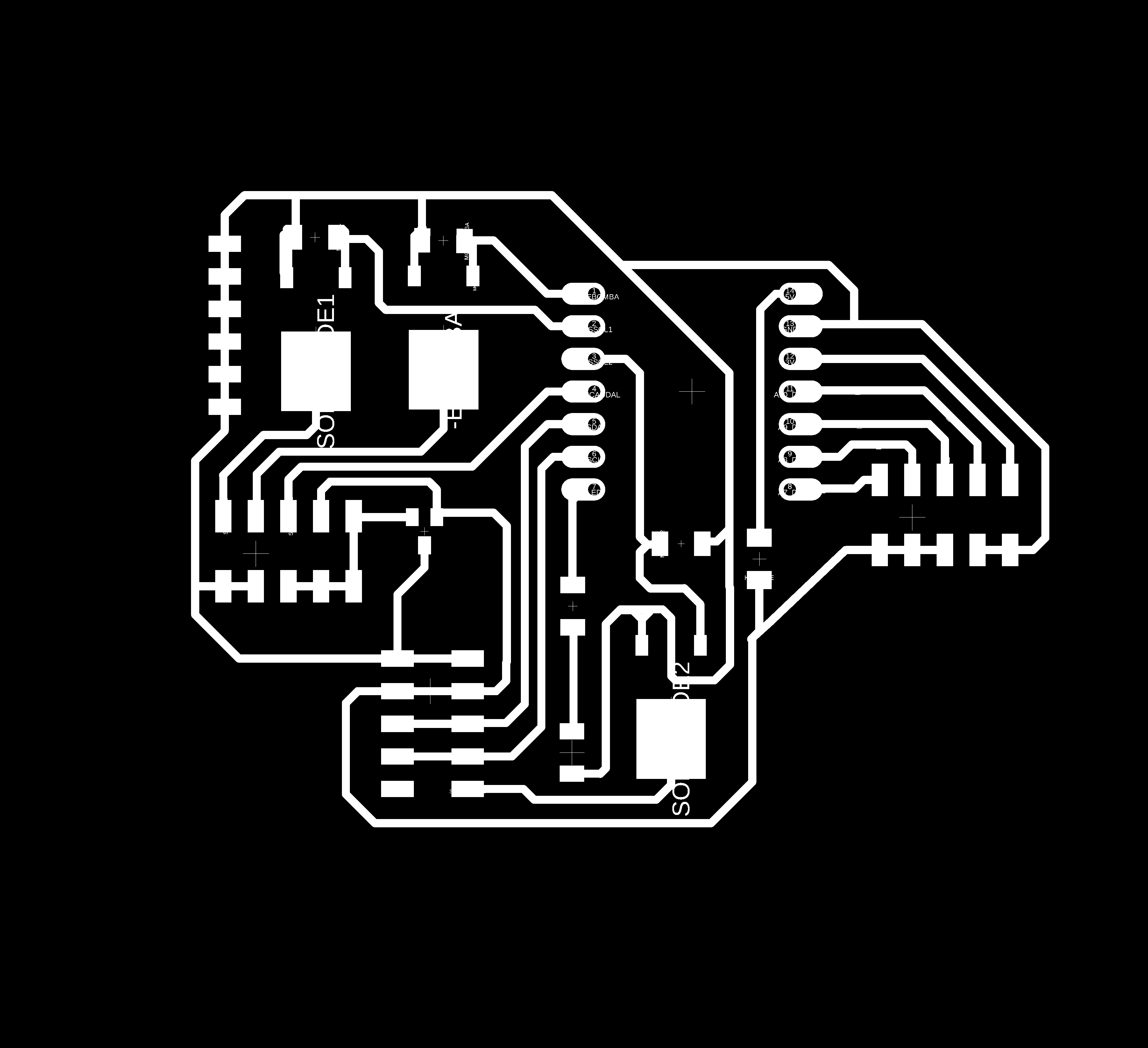
The first thing I started to design and then manufacture was the electronic board. I had previously mentioned that I should make another board that includes 3 MOSFETs: one for the electric pump and the other two for the solenoid valves.
To manufacture this board I followed the same steps as the first board, which were documented in week 9.
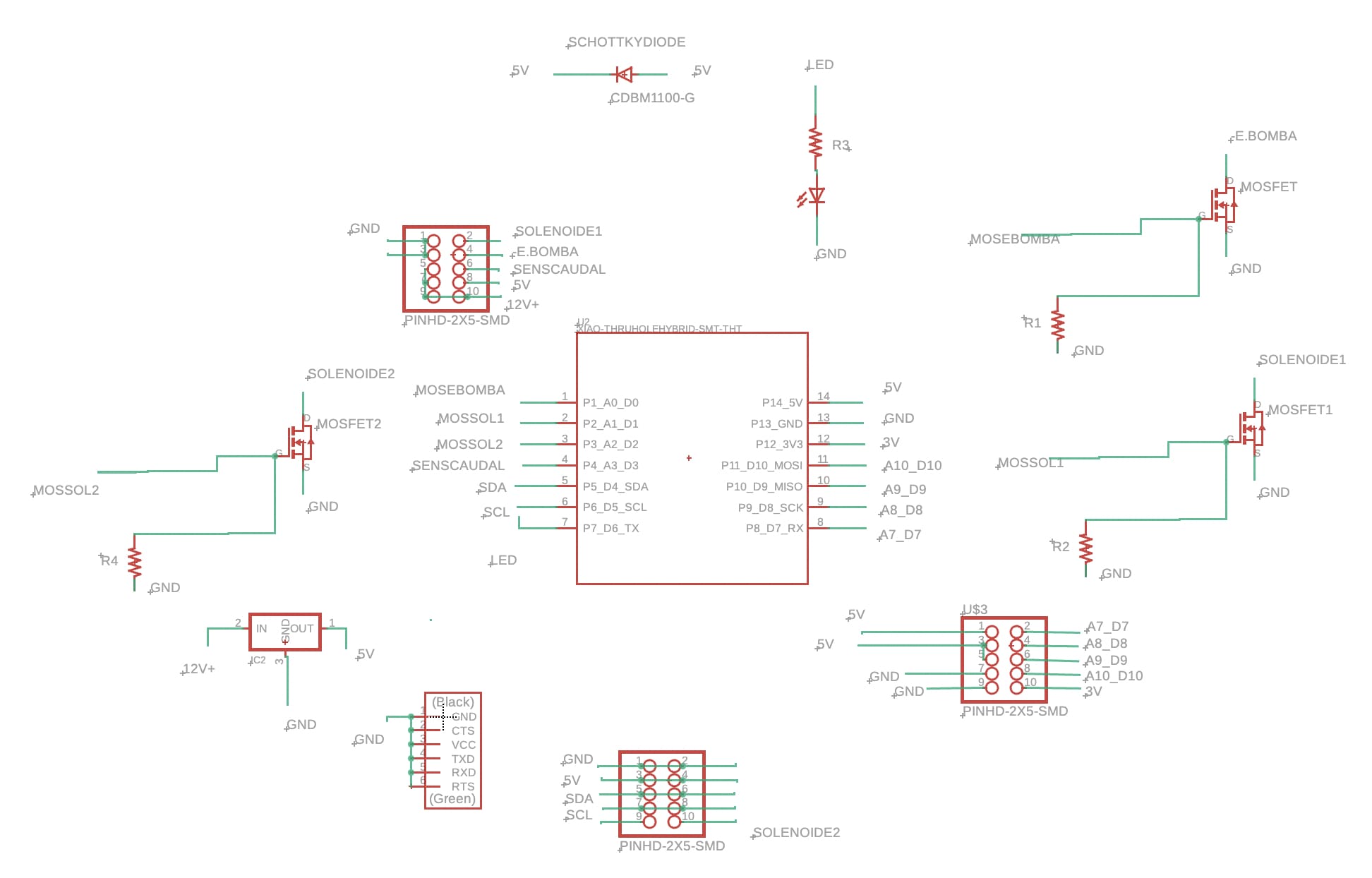
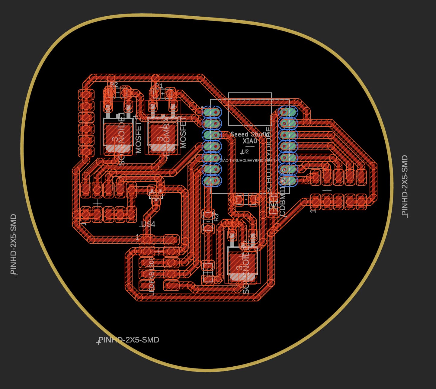
First I start with the design of the PCB in the fusion 360 software using the electronic design module, starting with the schematic to design and enter all the components that I will need.
In addition to the MOSFETs, I have now incorporated a voltage regulator from 12v to 5v so that the board can be powered with my external 12v source and also power the seeeduino with 5v. My design also includes a schottky diode in line with the 5v so that when I upload the code to my seeeduino it does not overheat the voltage regulator, and also protects the seeeduino from burning out.
Next I arrange the tracks and see what is the most efficient way to join them.
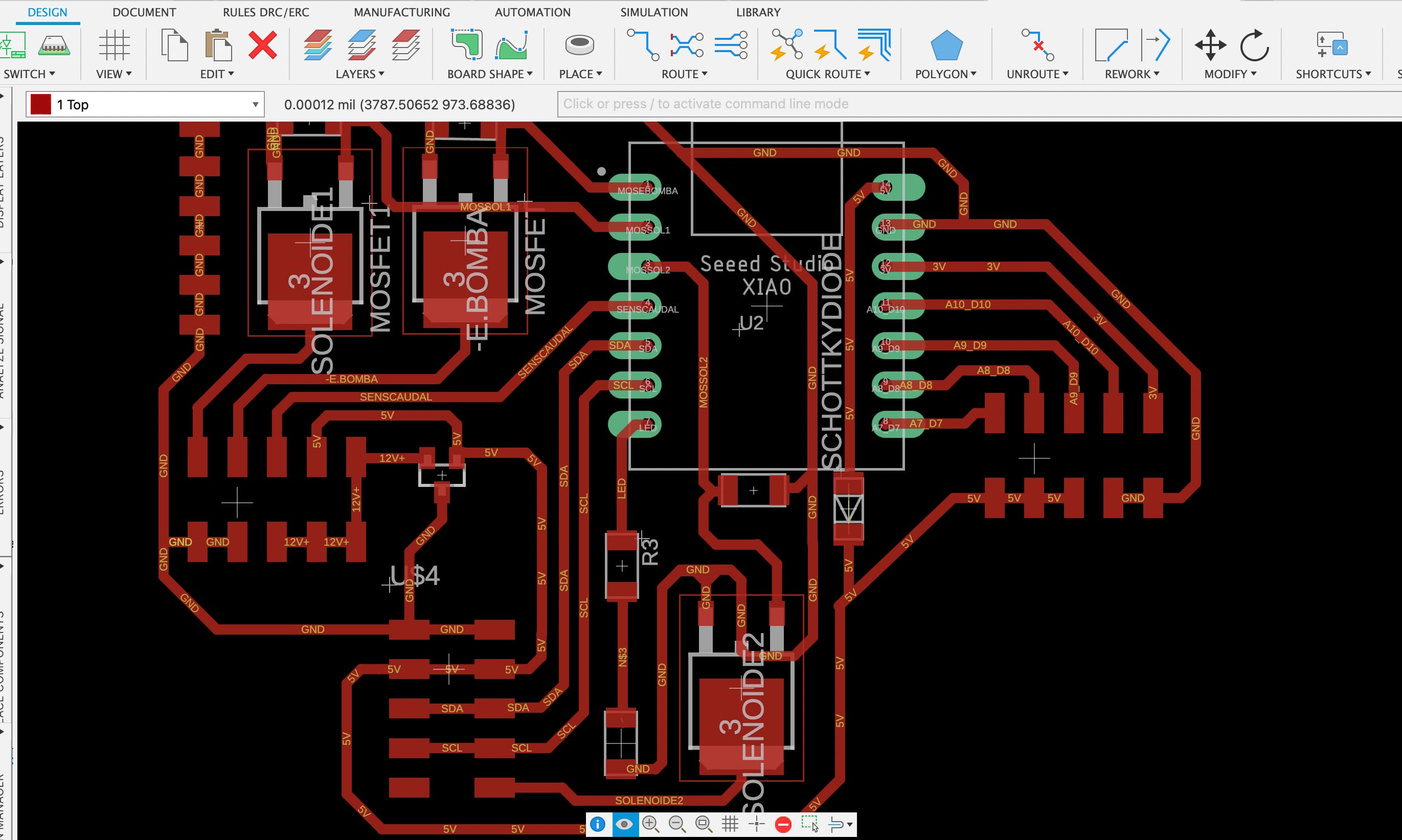
For this I used a manual rout of 24mill.
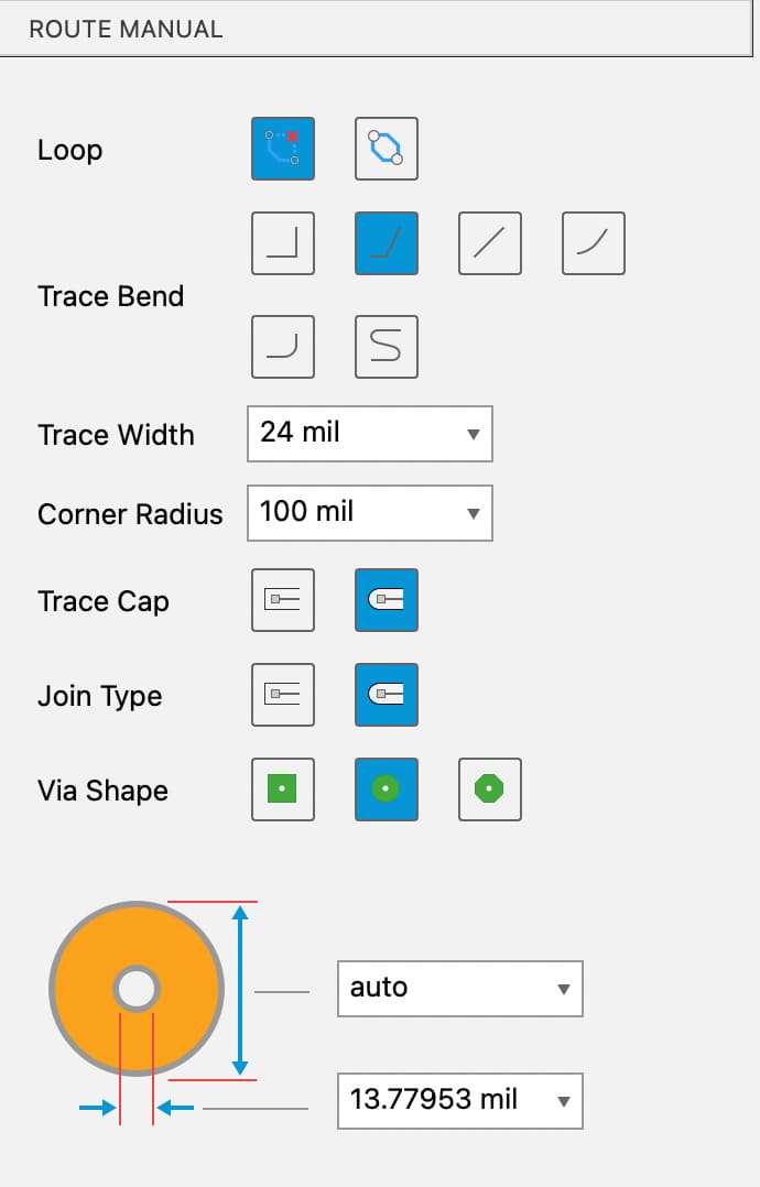
Below is a short video of what a track looks like with that thickness mentioned.
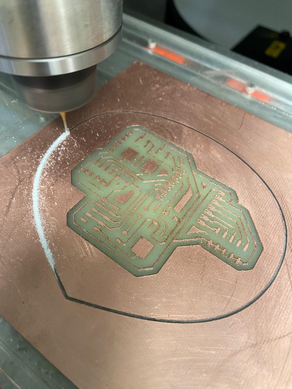
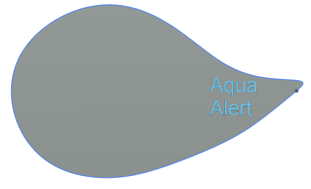
After that, I design the outline of the board. I decided to use a drop shape for the outline.
Next, I used Flatcam software for generate the NC codes of the 3 files: tracks, outline and thru hole for the male seeeduino pins.
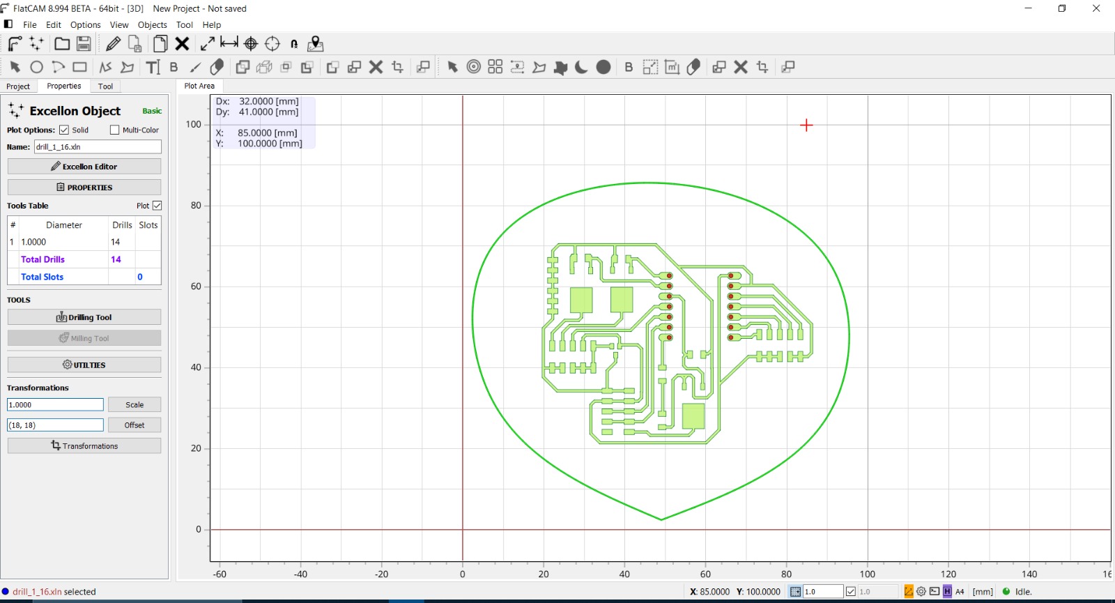
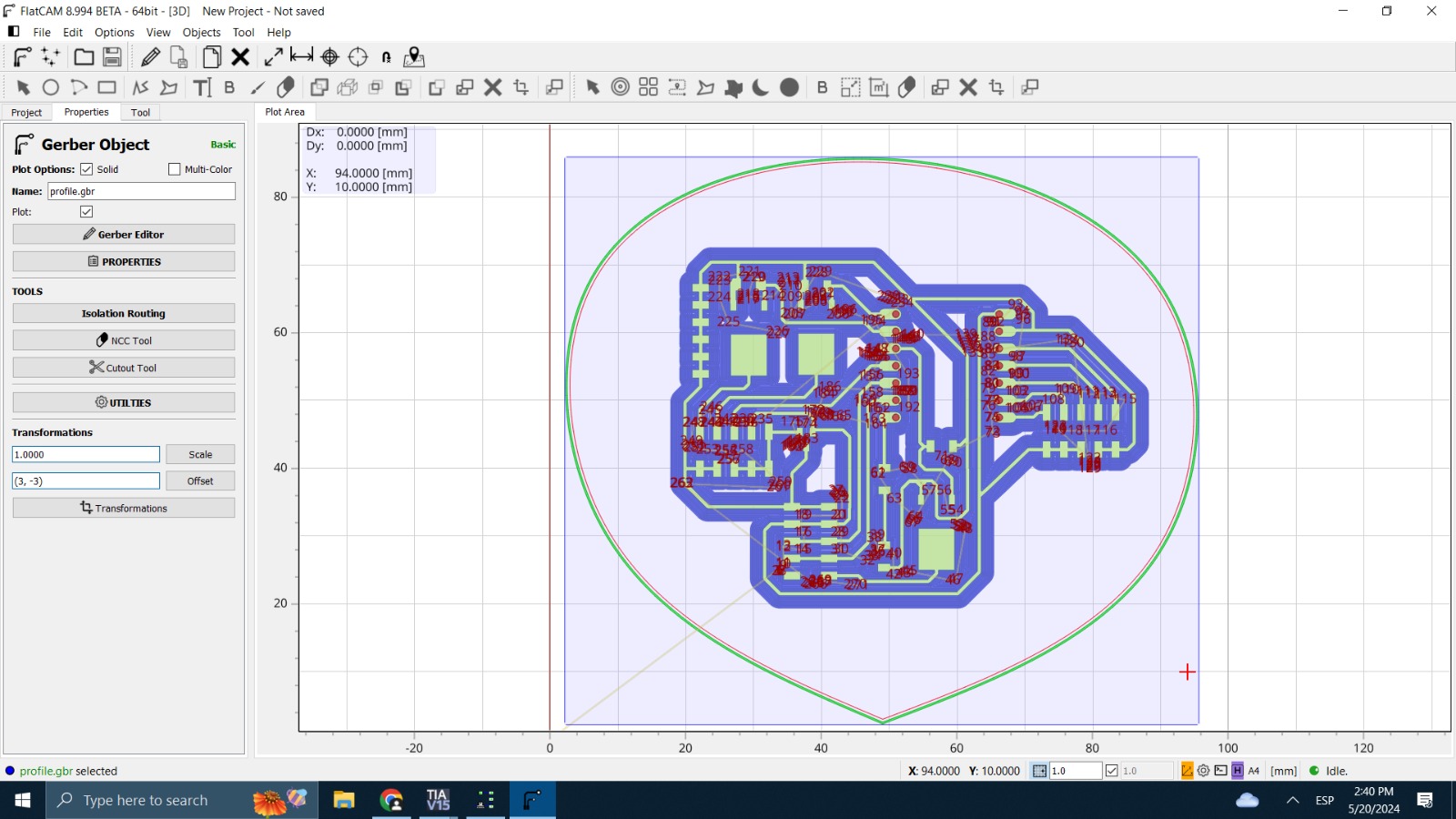
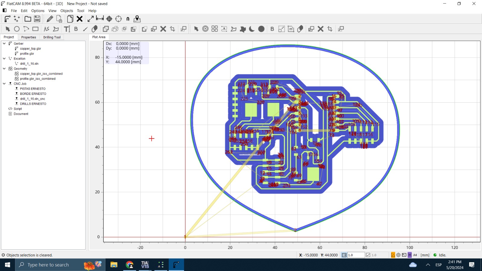
Then I use the Roland machine to manufacture the PCB from the 3 NC files delivered by flatcam software: tracks, outline and thru hole for the male seeeduino pins.
Next, I solder all the components SMD and male pins to the seeeduino.
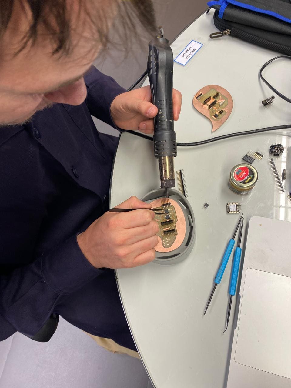
While I was soldering, I performed continuity tests with a multimeter to ensure that there was continuity of current in the copper tracks and components.
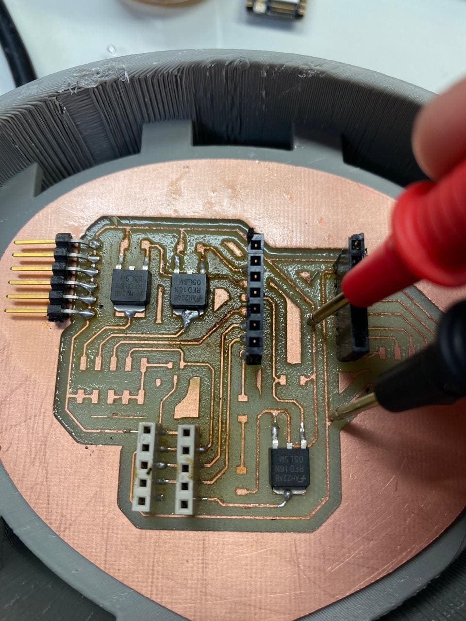
Finally, this is the result along with the cables connected to the other components of the project

2d and 3d design
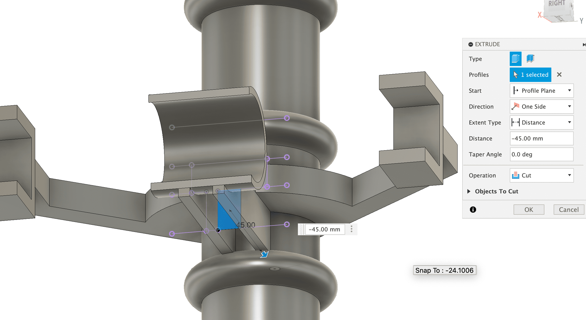
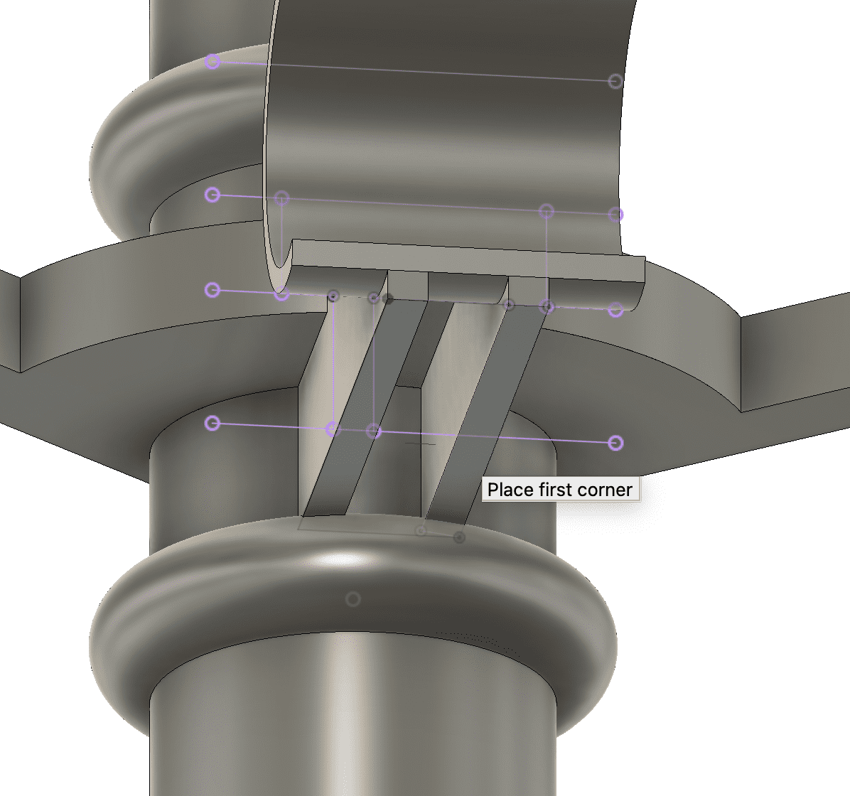
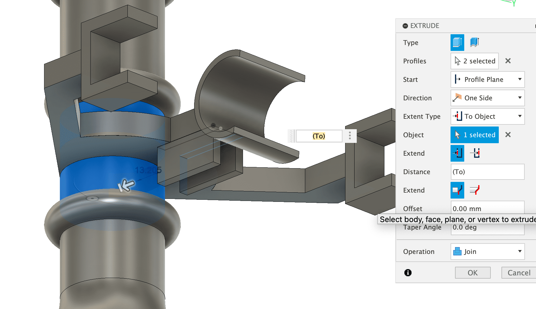
My final project includes designs in 2D as well as 3D. First, I started by laying out the entire base to hold the flow sensor, hoses, and solenoid valves.
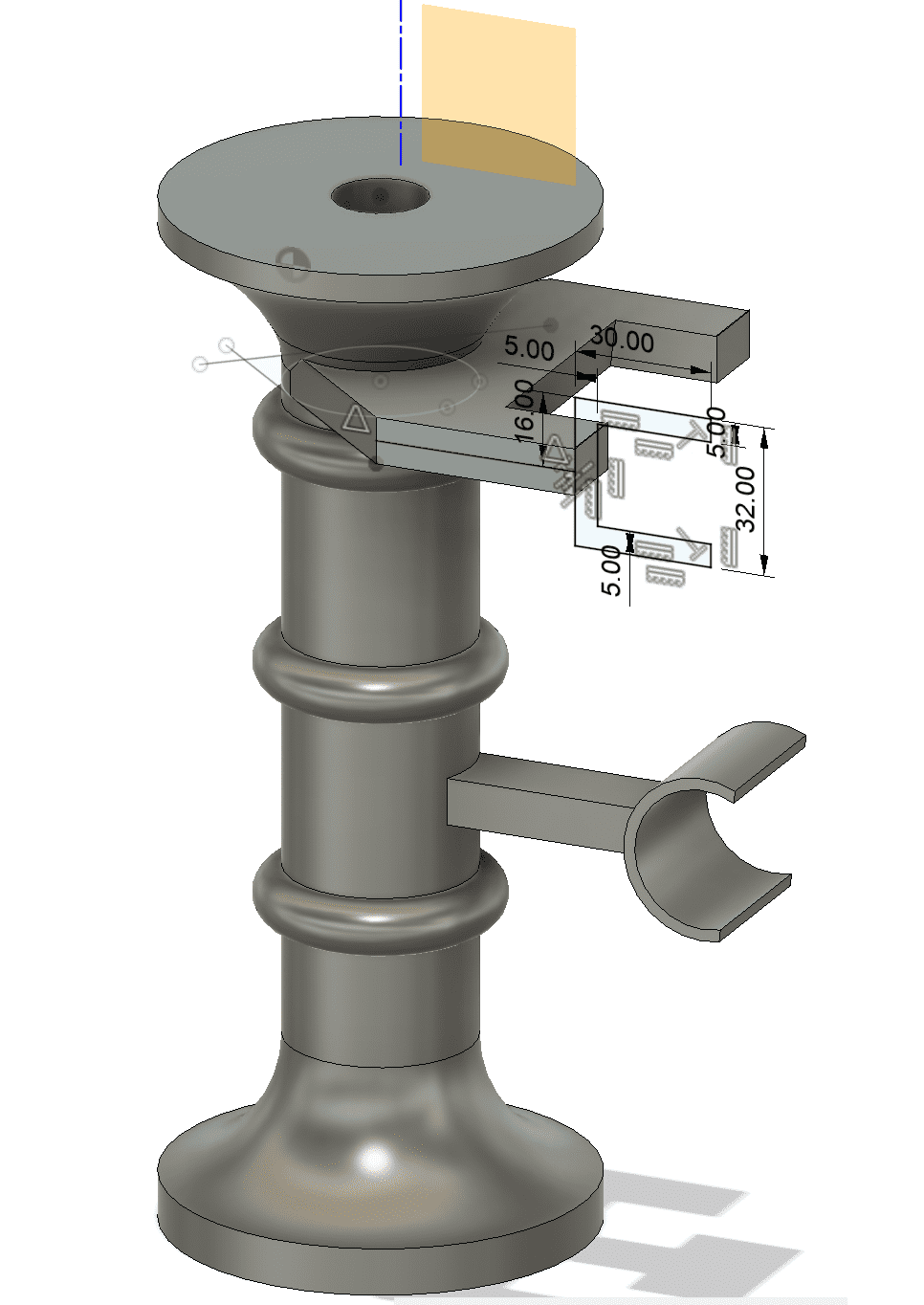 For this design, I had to first measure the sensor connections to join them to the hose system, as well as the solenoid valves. work with 0.2mm less than the measurements of my devices so that they can be held and pressed into the support.
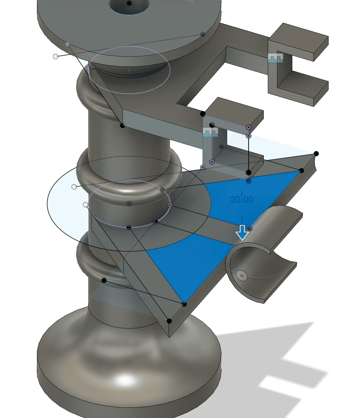 Also, I consider a system of spaces in the support so that the cables can be hidden.
 It was not necessary to make the base robust or consider high filling because the weight it was going to support was not decisive.
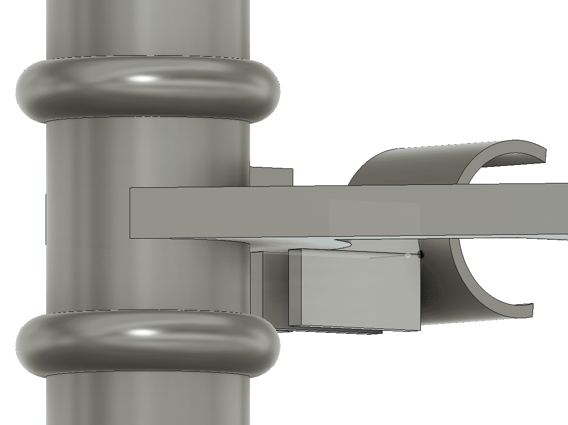
This is the base ready to attach the sensor and the two solenoid valves.
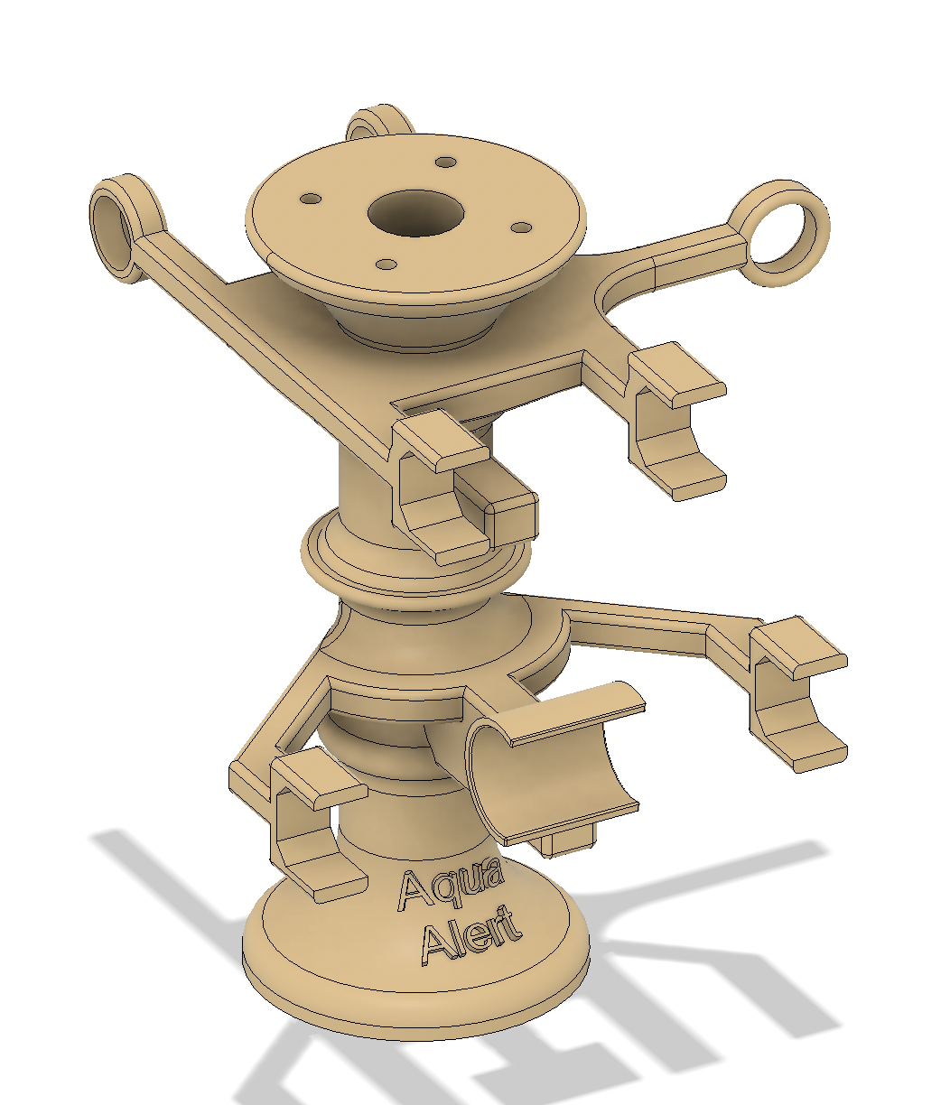
Finally, in order to attach the electronic board, I had to make another design that can be attached to this one. This design includes using an OLED screen as well.

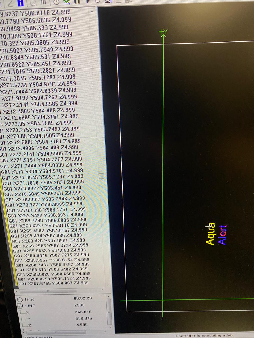
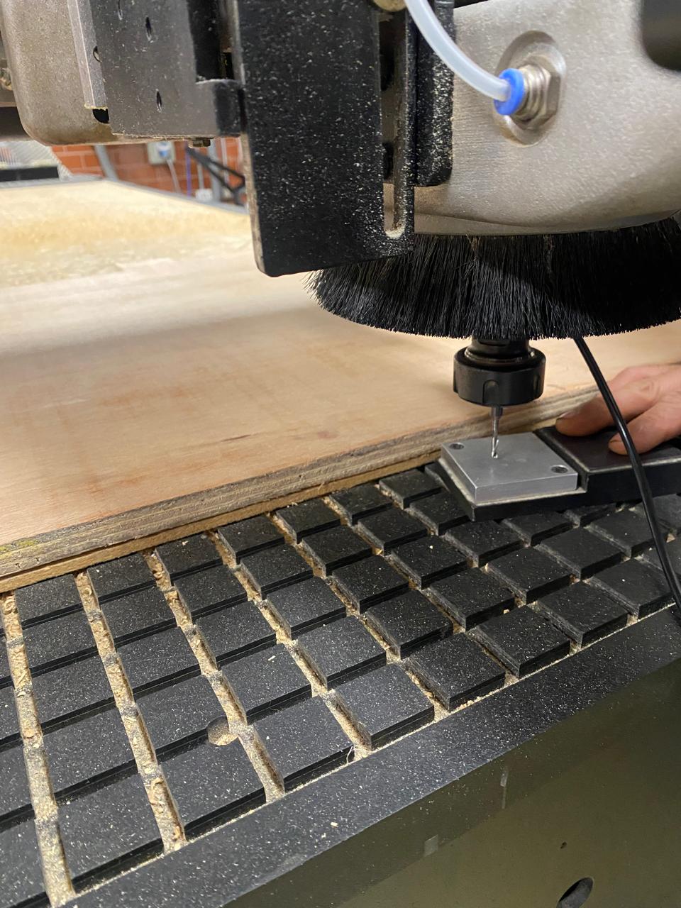
I also made the design of the base in the Fusion 360 software. Then, I used the Enroute software to generate the g-code and finished by cutting a piece in the drop shape. For this, I used the Multicam-3000 machine.
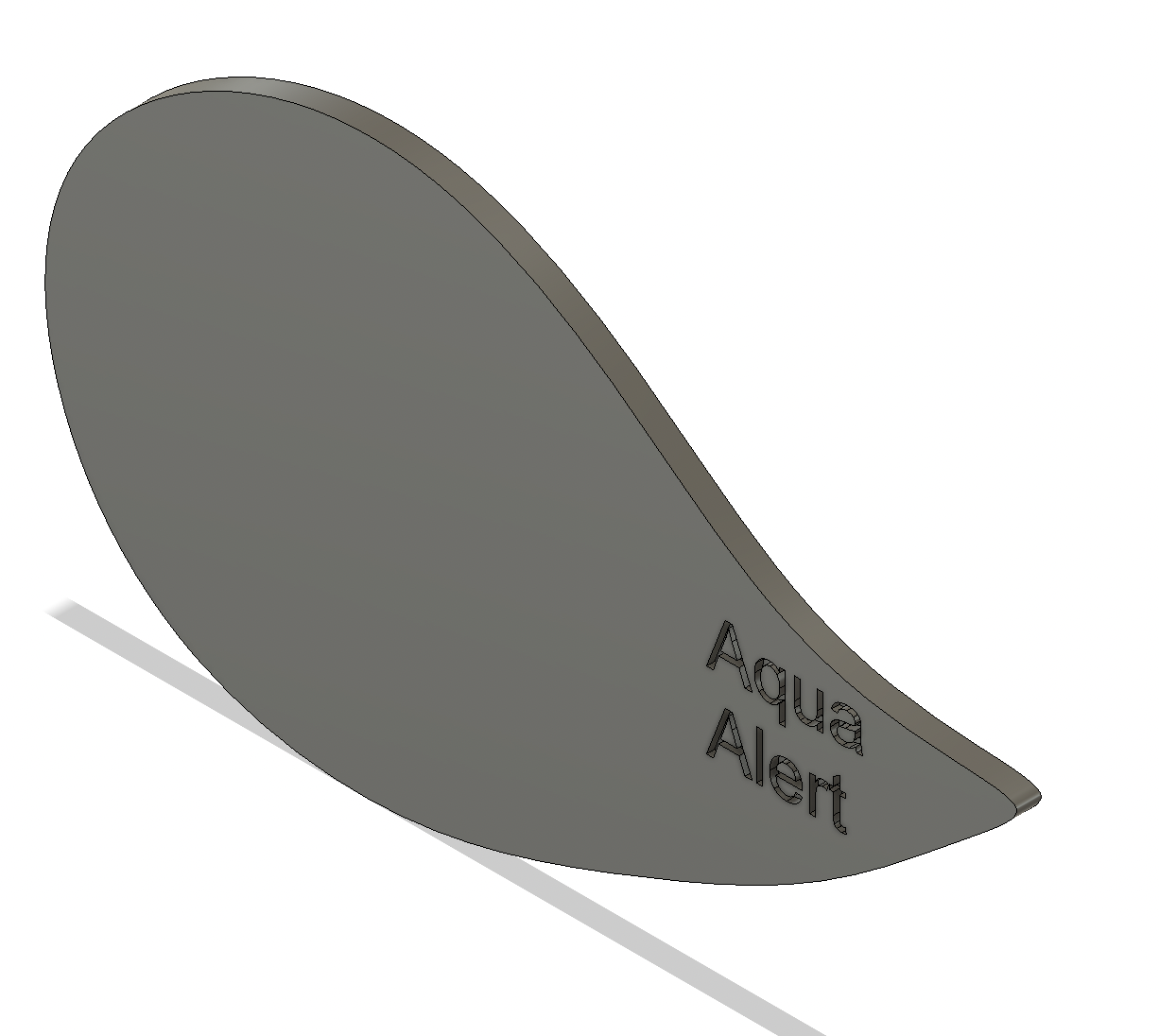
I used a 3mm of diameter mill for this operation.
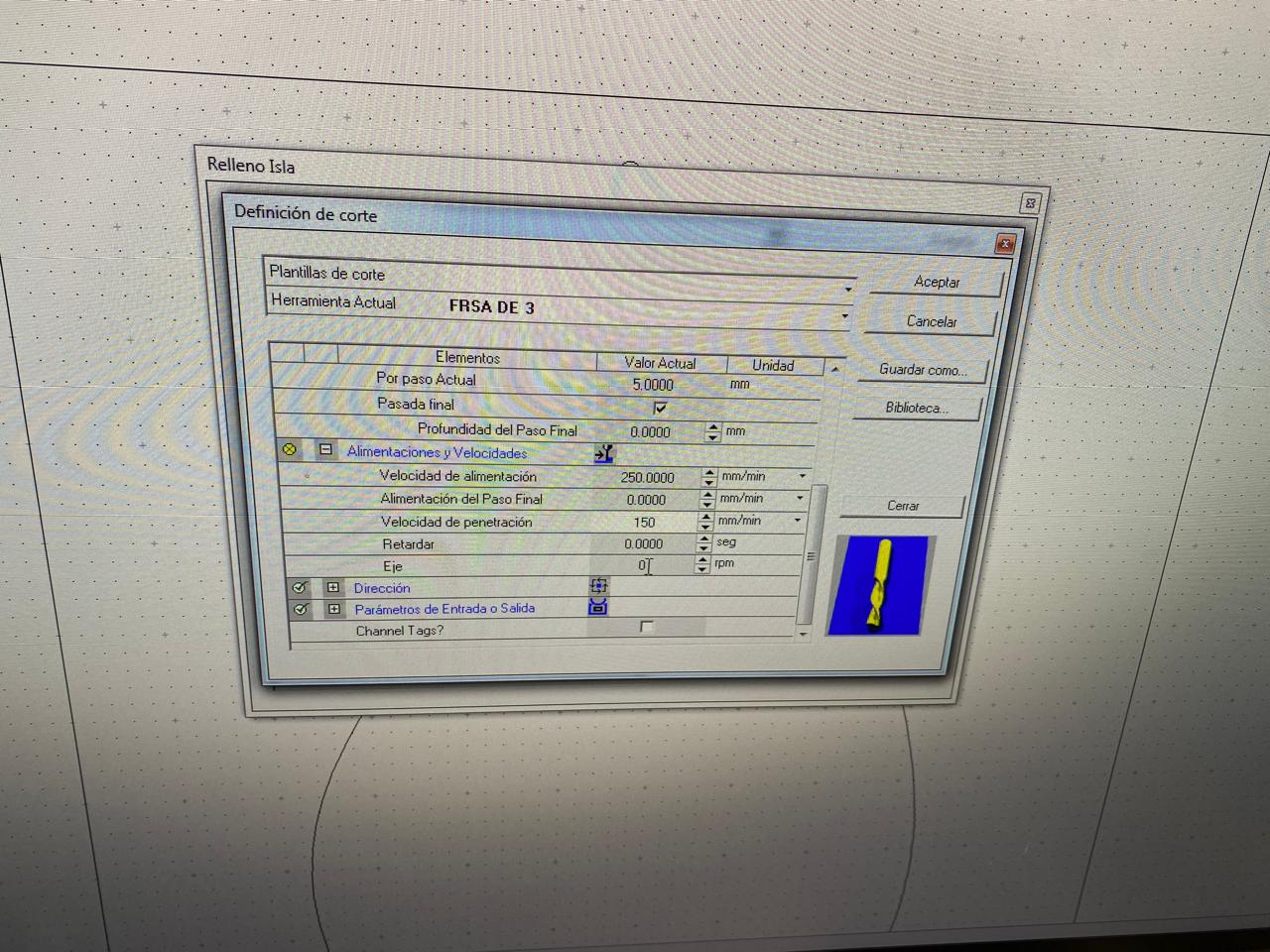
The software delivers the G-code and I put that code into the multicam-3000 machine.
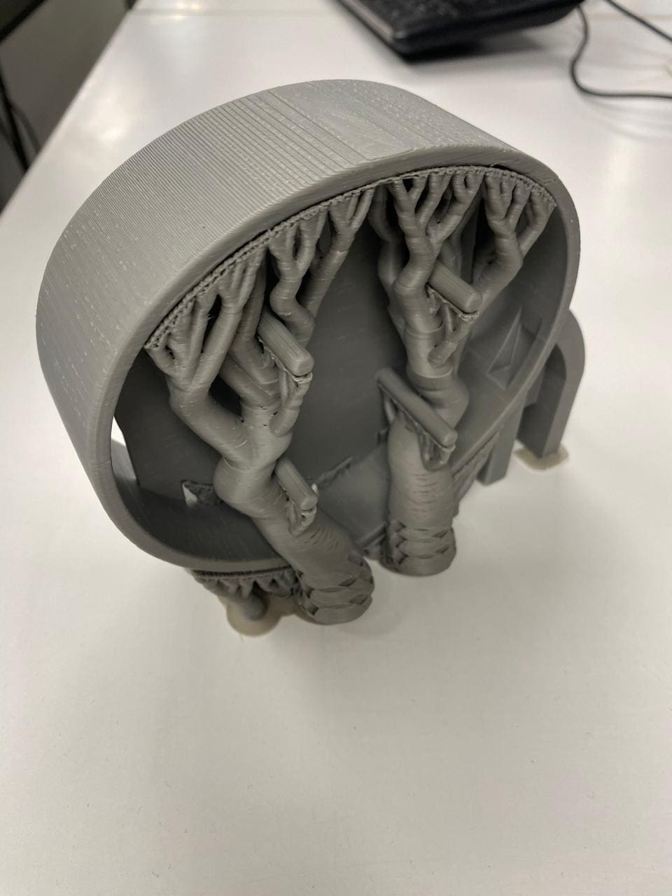
Thermoforming
I made the water tank with a thermoforming process of acrylic.
The process of thermoforming acrylic involves heating an acrylic sheet until it becomes malleable and then molding it into the desired shape. Here is a general overview of the process I made:
Material Preparation: An acrylic sheet of the 4mm of thickness is selected for the project.
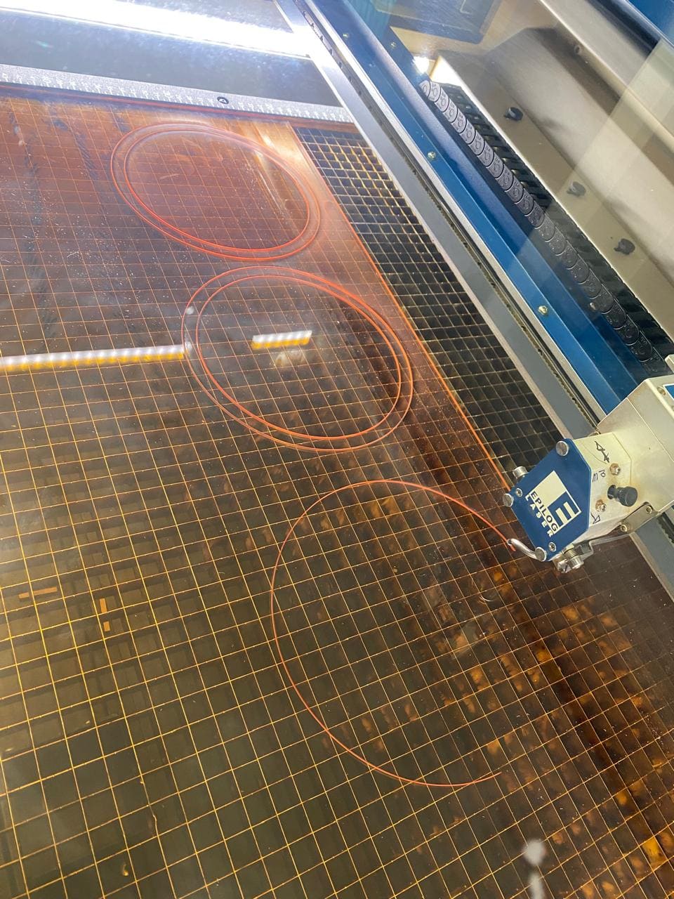
Heating: The acrylic sheet is heated to its thermoforming temperature, typically between 150°C and 170°C (300°F and 340°F). This was made with a heat gun.
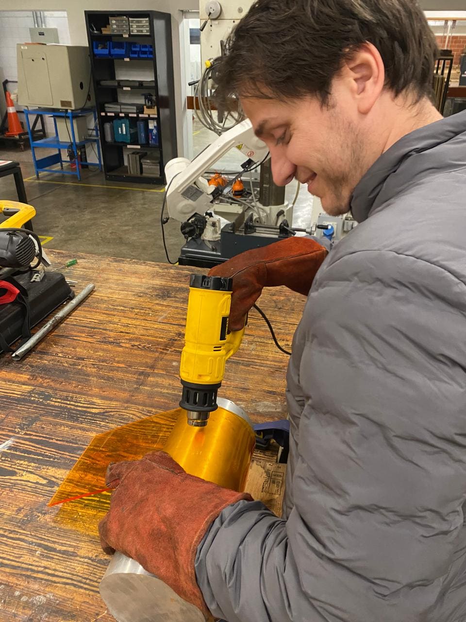
Molding: Once the sheet is hot and pliable, it is placed over and I gave it the shape I wanted.
Cooling: The molded sheet is allowed to cool maintain the desired shape. Cooling should be gradual to prevent warping or internal stresses in the material.
Final part
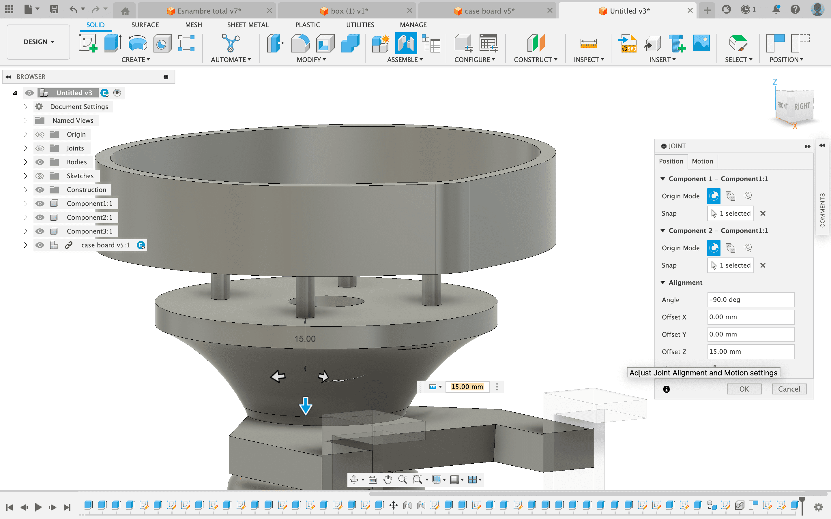
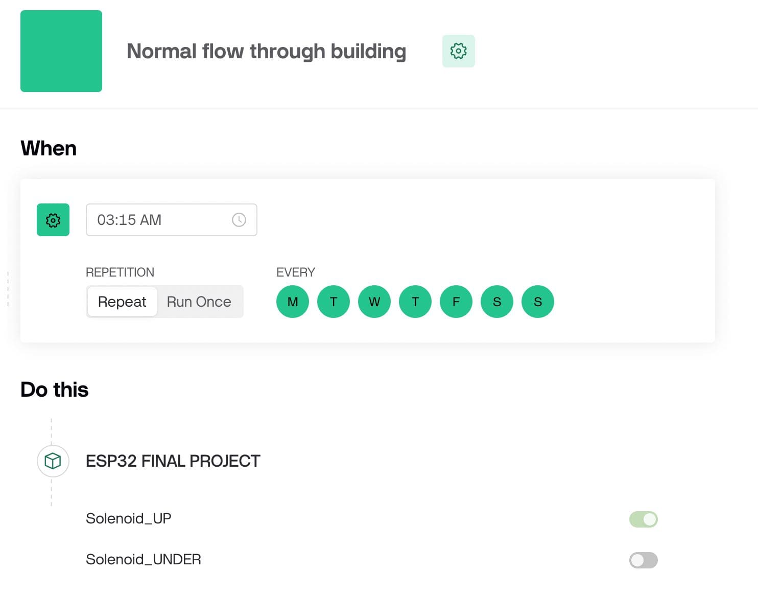
Finally, I made the programming code under the following logic: At 3:00 am the solenoid valve that is in the main pipe will close and will cause the fluid to go through the auxiliary pipe, opening the second solenoid valve that is below. This state will last 15 minutes, a proven time and sufficient to detect if there is a fluid, meaning that there is an abnormal consumption in that pipe. The idea of this is to prolong the life of the flow sensor.
I will also be working with the Blynk app connected via Wi-Fi to the seeeduino ESP32-C3. The sensor will be sending information to the app through the seeeduino, and also vice versa to be able to control the solenoid valves. I learned to work with this app in the week 14: interface and application programming.
The operating times will be programmed from the app Blynk. At first I thought of using an RTC (Real Time Clock) module which, as its name says, allows programming with a real-time clock. However, after studying the benefits of the seeeduino ESP32-C3's Wi-Fi connectivity and knowing the potential of the Blynk app, I decided to choose to work with this one.
The code was written in the Arduino IDE, and using the following libraries:
#include #include #include #include #include #include #include
#define BLYNK_TEMPLATE_ID "TMPL2L1JAtM3R" // Define the Blynk template ID
#define BLYNK_TEMPLATE_NAME "ESP32 FINAL PROJECT" // Define the Blynk template name
#define BLYNK_AUTH_TOKEN "vbwqd0jSgHx8SR12pEOhHkTO03UNKGyk" // Define the Blynk authentication token
#define BLYNK_PRINT Serial // Enable Serial output for debugging
#include #include #include #include #include #include #include // My WiFi credentials
char ssid[] = "Depa703"; // SSID where I made my project
char pass[] = "borgono10000"; // Password of the wifi network
// Flow sensor setup
FlowSensor Sensor(150, 8); // Create a flow sensor object with specific parameters, Pulses is 150 as the manufacturer say, port 8 of Seeeduino ESP32-C3
unsigned long lastCheck = 0; // Variable to keep track of the last check time
const int solenoidPinUP = 4; // Pin connected to the UP solenoid valve
const int solenoidPinUNDER = 2; // Pin connected to the UNDER solenoid valve
const int mosfetPinPump = 3; // Pin connected to the MOSFET for the pump
// OLED display setup
#define SCREEN_WIDTH 128 // Define the width of the OLED display
#define SCREEN_HEIGHT 64 // Define the height of the OLED display
#define OLED_RESET -1 // Define the OLED reset pin (not used here)
Adafruit_SSD1306 display(SCREEN_WIDTH, SCREEN_HEIGHT, &Wire, OLED_RESET); // Create an OLED display object
// System states
enum SystemState {
NORMAL_FLOW,
ALERT,
DISPLAY_FLOW_RATE,
DISPLAY_COST
};
SystemState currentState = NORMAL_FLOW; // Set the initial system state to NORMAL_FLOW
unsigned long stateStartTime = 0; // Variable to store the state start time
unsigned long stateDuration = 0; // Variable to store the state duration
// Variables to control the solenoids and the pump from Blynk
bool solenoidUPState = false; // Initial state of the UP solenoid valve
bool solenoidUNDERState = false; // Initial state of the UNDER solenoid valve
bool pumpState = true; // Turn on the pump by default
void count() {
Sensor.count(); // Increment the flow sensor counter
}
void setup() {
// Debug console
Serial.begin(115200); // Initialize the Serial communication at 115200 baud rate
// Connect to Blynk
Blynk.begin(BLYNK_AUTH_TOKEN, ssid, pass); // Connect to Blynk using the authentication token and WiFi credentials
// Initialize the flow sensor
Sensor.begin(count); // Initialize the flow sensor with the count function
// Set the pins as outputs and activate them
pinMode(solenoidPinUP, OUTPUT); // Set the UP solenoid pin as an output
pinMode(solenoidPinUNDER, OUTPUT); // Set the UNDER solenoid pin as an output
pinMode(mosfetPinPump, OUTPUT); // Set the MOSFET pump pin as an output
// Turn on the pump at the start
digitalWrite(mosfetPinPump, HIGH); // Turn on the pump by setting the pin HIGH
// Initialize the OLED display
if (!display.begin(SSD1306_SWITCHCAPVCC, 0x3C)) { // Initialize the display with I2C address 0x3C
Serial.println(F("SSD1306 allocation failed")); // Print an error message if the display initialization fails
for (;;); // Enter an infinite loop if the initialization fails
}
display.display(); // Display the initial buffer
delay(2000); // Small delay for the display initialization
display.clearDisplay(); // Clear the display buffer
display.setTextSize(2); // Set the text size for the display
display.setTextColor(SSD1306_WHITE); // Set the text color for the display
Serial.println(F("OLED display initialized successfully")); // Print a success message for the display initialization
// Set the initial state
currentState = NORMAL_FLOW; // Set the initial state to NORMAL_FLOW
stateStartTime = millis(); // Record the current time as the state start time
stateDuration = 10000; // Set the duration for NORMAL_FLOW state to 10 seconds
// Ensure the solenoids and pump are in the correct state at the start
digitalWrite(solenoidPinUP, solenoidUPState); // Set the UP solenoid state
digitalWrite(solenoidPinUNDER, solenoidUNDERState); // Set the UNDER solenoid state
digitalWrite(mosfetPinPump, pumpState); // Set the pump state
}
// Blynk functions to handle the solenoid and pump switches
BLYNK_WRITE(V0) {
solenoidUPState = param.asInt(); // Get the value from the Blynk app for the UP solenoid
digitalWrite(solenoidPinUP, solenoidUPState); // Set the UP solenoid state
Blynk.virtualWrite(V0, solenoidUPState); // Update the switch state in the Blynk dashboard
}
BLYNK_WRITE(V2) {
solenoidUNDERState = param.asInt(); // Get the value from the Blynk app for the UNDER solenoid
digitalWrite(solenoidPinUNDER, solenoidUNDERState); // Set the UNDER solenoid state
Blynk.virtualWrite(V2, solenoidUNDERState); // Update the switch state in the Blynk dashboard
}
BLYNK_WRITE(V3) {
pumpState = param.asInt(); // Get the value from the Blynk app for the pump
digitalWrite(mosfetPinPump, pumpState); // Set the pump state
Blynk.virtualWrite(V3, pumpState); // Update the switch state in the Blynk dashboard
}
void loop() {
Blynk.run(); // Run the Blynk main loop
unsigned long currentTime = millis(); // Get the current time
if (currentTime - stateStartTime >= stateDuration) {
// Change state if the duration has passed
switch (currentState) {
case NORMAL_FLOW:
currentState = ALERT; // Change to ALERT state
stateDuration = 2000; // Set duration for ALERT state
break;
case ALERT:
currentState = DISPLAY_FLOW_RATE; // Change to DISPLAY_FLOW_RATE state
stateDuration = 2000; // Set duration for DISPLAY_FLOW_RATE state
break;
case DISPLAY_FLOW_RATE:
currentState = DISPLAY_COST; // Change to DISPLAY_COST state
stateDuration = 2000; // Set duration for DISPLAY_COST state
break;
case DISPLAY_COST:
{
static int cycleCount = 0; // Static variable to count cycles
cycleCount++;
if (cycleCount >= 3) { // Repeat the cycle 3 times
cycleCount = 0; // Reset cycle count
currentState = NORMAL_FLOW; // Change back to NORMAL_FLOW state
stateDuration = 10000; // Set duration for NORMAL_FLOW state
} else {
currentState = ALERT; // Change back to ALERT state
stateDuration = 2000; // Set duration for ALERT state
}
break;
}
}
stateStartTime = currentTime; // Update the state start time
// Actions based on the current state
switch (currentState) {
case NORMAL_FLOW:
digitalWrite(solenoidPinUP, HIGH); // Open UP solenoid
digitalWrite(solenoidPinUNDER, LOW); // Close UNDER solenoid
display.clearDisplay(); // Clear the display
display.setCursor((SCREEN_WIDTH - 12 * 6) / 2, (SCREEN_HEIGHT - 16) / 2); // Center text
display.println("NORMAL"); // Display NORMAL
display.setCursor((SCREEN_WIDTH - 4 * 6) / 2, (SCREEN_HEIGHT - 16) / 2 + 16); // Center text
display.println("FLOW"); // Display FLOW
display.display(); // Update the display
Serial.println("State: NORMAL_FLOW"); // Print state to Serial
break;
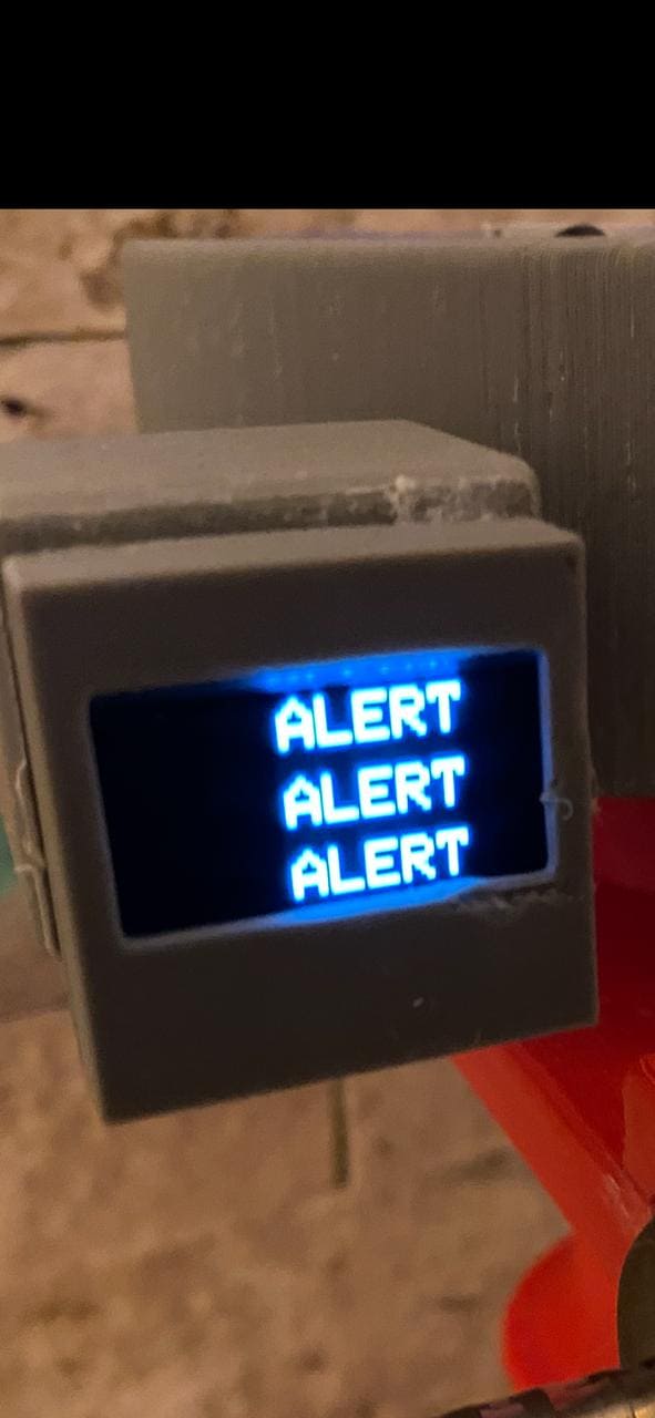
case ALERT:
digitalWrite(solenoidPinUP, LOW); // Close UP solenoid
digitalWrite(solenoidPinUNDER, HIGH); // Open UNDER solenoid
display.clearDisplay(); // Clear the display
display.setCursor((SCREEN_WIDTH - 5 * 6) / 2, 0); // Center text
display.println("ALERT"); // Display ALERT
display.setCursor((SCREEN_WIDTH - 5 * 6) / 2, 24); // Center text
display.println("ALERT"); // Display ALERT
display.setCursor((SCREEN_WIDTH - 5 * 6) / 2, 48); // Center text
display.println("ALERT"); // Display ALERT
display.display(); // Update the display
Serial.println("State: ALERT"); // Print state to Serial
break;
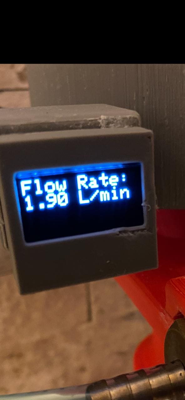
case DISPLAY_FLOW_RATE:
{
Sensor.read(); // Read the flow sensor
float flowRate = Sensor.getFlowRate_m(); // Get the flow rate in L/min
Blynk.virtualWrite(V1, flowRate); // Update the flow rate in the Blynk app
display.clearDisplay(); // Clear the display
display.setCursor(0, 0); // Set cursor position
display.println("Flow Rate:"); // Display Flow Rate label
display.print(flowRate); // Display the flow rate
display.println(" L/min"); // Display units
display.display(); // Update the display
Serial.print("Flow Rate: "); // Print flow rate to Serial
Serial.print(flowRate); // Print the flow rate value
Serial.println(" L/min"); // Print units to Serial
break;
}
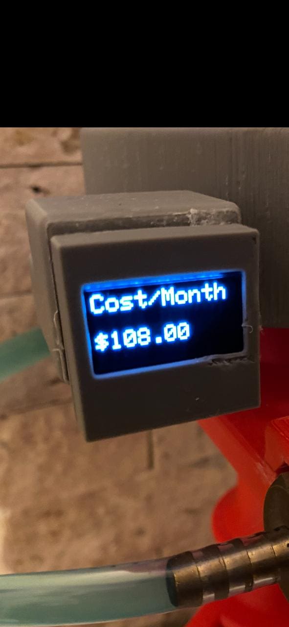
case DISPLAY_COST:
{
Sensor.read(); // Read the flow sensor
float flowRate = Sensor.getFlowRate_m(); // Get the flow rate in L/min
float monthlyCost = flowRate * 60 * 24 * 30 * 0.005 / 4; // Calculate the monthly cost
display.clearDisplay(); // Clear the display
display.setCursor(0, 0); // Set cursor position
display.println("Cost/Month"); // Display Cost/Month label
display.setCursor(0, 32); // Set cursor position
display.print("$"); // Display currency symbol
display.println(monthlyCost); // Display the monthly cost
display.display(); // Update the display
Serial.print("Cost/Month: $"); // Print monthly cost to Serial
Serial.println(monthlyCost); // Print the cost value to Serial
break;
}
}
}
// Update the state of the solenoids and pump in the Blynk dashboard
Blynk.virtualWrite(V0, digitalRead(solenoidPinUP)); // Update UP solenoid state
Blynk.virtualWrite(V2, digitalRead(solenoidPinUNDER)); // Update UNDER solenoid state
Blynk.virtualWrite(V3, digitalRead(mosfetPinPump)); // Update pump state
}
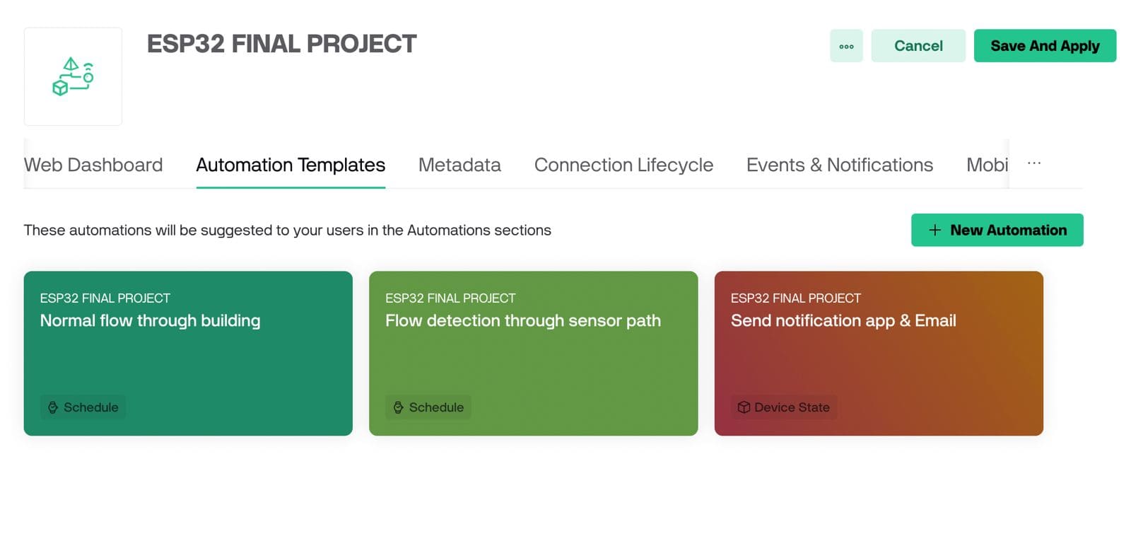
This is the final part of my project, and where with the information I receive through my seeeduino ESP32-C3 I can make decisions on the Blynk platform. Here you configure the alarms and the operating timing of the solenoid valves at the time they have to open or close.
First I had to create the working interface with my solenoids and sensor reading
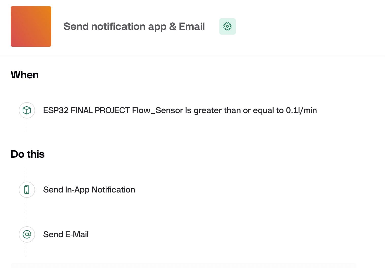
Then I programed the alarms with the condition that if the sensor detects any water flow, it will send the alert to the user's cell phone.
These are the alerts that are reflected on the OLED screen, depending on each case.
Project Slide
Files:
Traces png
Program code
Wifi integration via Blynk platform

Project video
Outline png
Drills png
Drills for flatcam
Tracks for flatcam
Outline for flatcam
Drills NC code for Roland
Drills NC code for Roland
Outline NC code for Roland
Acrylic top cover stl
Base stl
Final project stl
Final project code IDE arduino