9. Input Devices
Welcome to week number 9, input devices.
GROUP ASSIGNMENT: - Probe an input device(s)’s analog levels and digital signals. - Document your work on the group work page and reflect on your individual page what you learned.
INDIVIDUAL ASSIGNMENT: - Measure something: add a sensor to a microcontroller board that you have designed and read it.
Assignment Checklist.
| item | Activity | Status |
|---|---|---|
| task 1 | Linked to the group assignment page. | DONE |
| task 2 | Documented what you learned from interfacing an input device(s) to your microcontroller and optionally, how the physical property relates to the measured results. | DONE |
| task 3 | Documented your design and fabrication process or linked to the board you made in a previous assignment. | DONE |
| task 4 | Explained the programming process(es) you used. | DONE |
| task 5 | Explained any problems you encountered and how you fixed them. | DONE |
| task 6 | Included original design files and source code. | DONE |
| task 7 | Included a ‘hero shot’ of your board. | DONE |
GROUP ASSIGNMENT
MEASURING EQUIPMENT AND INSTRUMENTS.
For the effective way of taking measurements, we use measuring instruments, now for the INPUT DEVICES week, we will use the already known OSCILLOSCOPY.
OSCILLOSCOPY.
Electronic measuring instrument for displaying electrical signals at a given time. These signals are expressed in graphs in which an electron beam passes through a coordinate axis on a screen.
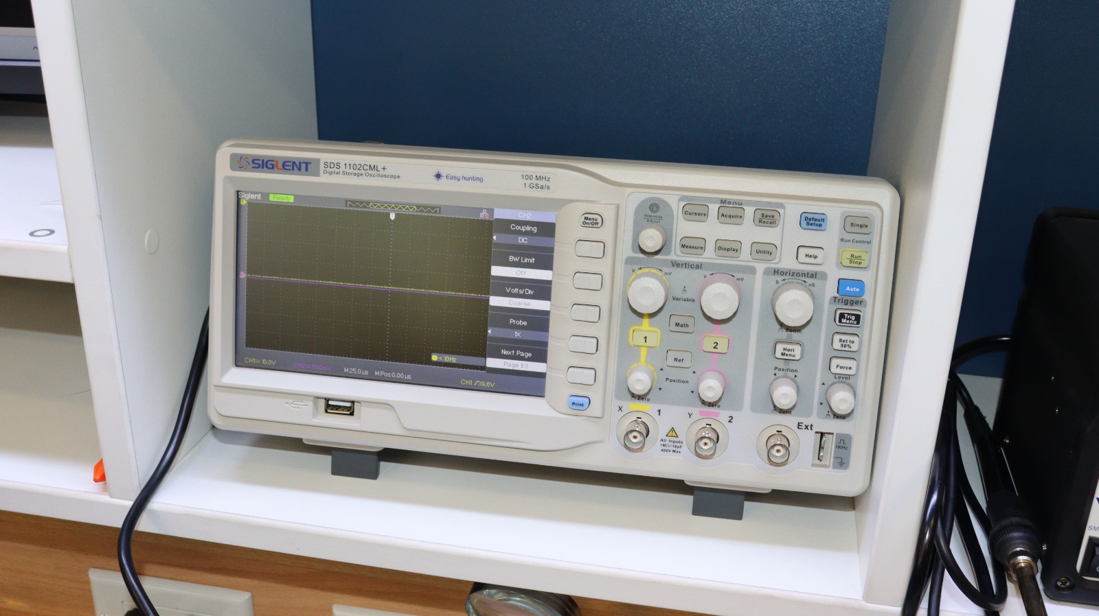
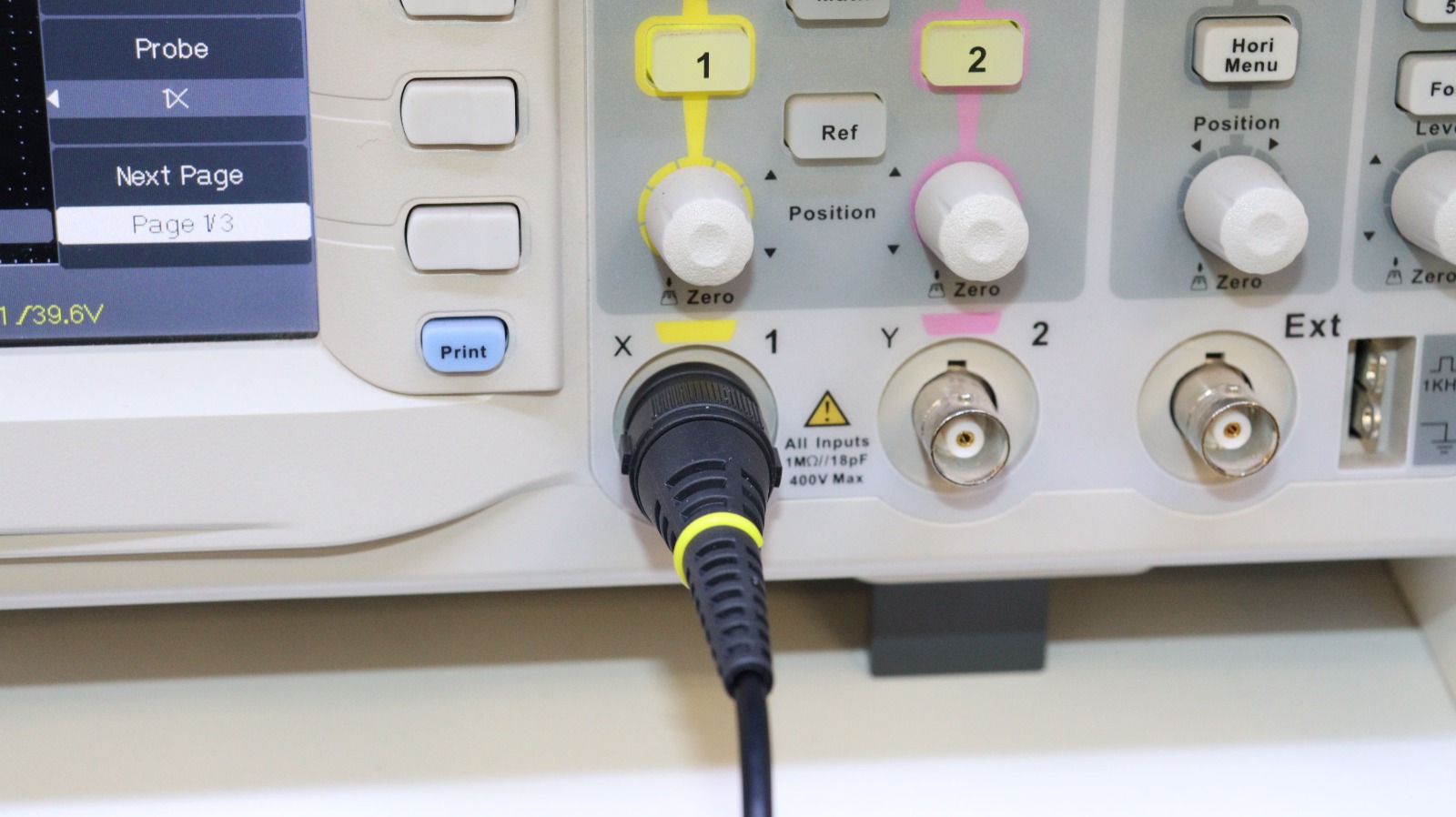
We will make the connection on channel 1, for collecting samples, and configuring the type of signal that we will take for reading.
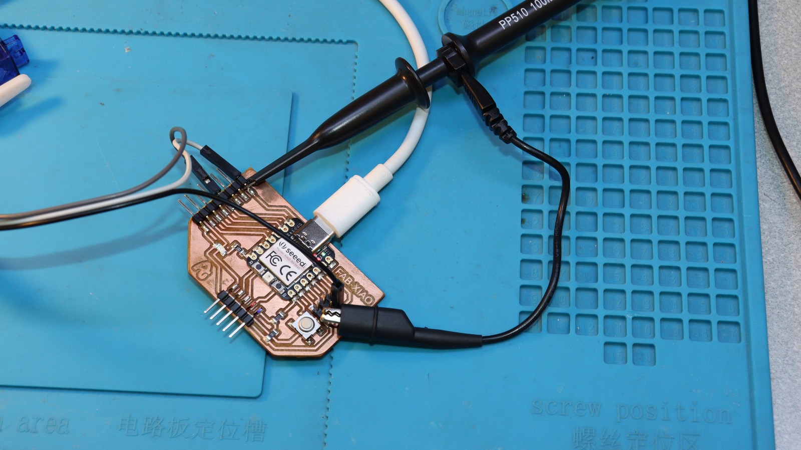
We will perform the initial test of measuring the input voltage to the board.

Code Example
Use the three backticks to separate code.
// the setup function runs once when you press reset or power the board
void setup() {
  // initialize digital pin LED_BUILTIN as an output.
  pinMode(LED_BUILTIN, OUTPUT);
}

// the loop function runs over and over again forever
void loop() {
  digitalWrite(LED_BUILTIN, HIGH);   // turn the LED on (HIGH is the voltage level)
  delay(1000);                       // wait for a second
  digitalWrite(LED_BUILTIN, LOW);    // turn the LED off by making the voltage LOW
  delay(1000);                       // wait for a second
}
Light Meter Sensor Module.
BH1750
It is a light sensor module, being this digital, it gives us measurement values in Lux, that is, the Lumen per square meter, standard unit of measurement for the lighting level, it has high precision with a range of 1 - 65535lx, which can be configured.

I2C Communication on Arduino - BH1750
The I2C protocol operates on a master-slave architecture. The master initiates and coordinates communication. In slave mode, these are devices waiting for a master to communicate with them, such as sensors and actuators that support this protocol.

- SDA (Serial Data Line): It is used for data transmission.
- SCL ( Serial Clock Line): Provides the clock signal that synchronizes communication.
These two pins are the ones we work with to achieve communication between the Arduino board, as well as the SeeedXiao-RP 2040 model. To obtain readings from the light sensor, model, BH1750.
Light Sensor Module with Arduino Nano.
For the first demonstration of the operation of the light sensor, BH1750, an Arduino Nano board with the expansion shield will be used. It should be understood that this is an input for light recording.
The connection is made as follows:
| BH1750-Pin | Arduino Nano Pin Conection |
|---|---|
| VCC | 5V |
| GND | GND |
| SDA | A4 |
| SCL | A5 |

Code.
#include <Wire.h>    // Librería para protocolo I2C
#include <BH1750.h>  // Librería para el sensor de luz BH1750

BH1750 luxSensor;    // Instancia del sensor

void setup() {
  Serial.begin(9600);   // Comunicación serial para mostrar datos en el monitor serial
  Wire.begin();         // Inicia I2C en Arduino Nano (SDA = A4, SCL = A5)
  luxSensor.begin();    // Inicializa el sensor BH1750

  Serial.println(F("Lectura de luxes desde el sensor BH1750"));
}

void loop() {
  float lux = luxSensor.readLightLevel();  // Lectura de nivel de luz en lux
  Serial.print("Luz: ");
  Serial.print(lux);
  Serial.println(" lx");
  delay(1000);  // Espera de 1 segundo entre lecturas
}
Operational Demonstration Video

Light Sensor Module with Seed XIAO - RP2040.
Now to make the connections on the board, we will have the following considerations, the I2C in the XIO RP2040, is as follows:
| BH1750-Pin | XIOA RP2040 Pin | Description |
|---|---|---|
| VCC | 3.3 V | Voltage |
| GND | GND | Ground |
| SDA | D4 (GPIO6) | I2C Comunication |
| SCL | D5 (GPIO7) | I2C Comunication |
Code for Seeed XIAO RP2040.
#include <Wire.h>
#include <BH1750.h>

BH1750 luxSensor;

void setup() {
  Serial.begin(9600);
  delay(1000); // Esperar para asegurar inicio correcto del puerto serial

  // Inicializa el bus I2C en los pines del XIAO RP2040 (SDA = 6, SCL = 7)
  Wire.setSDA(6);
  Wire.setSCL(7);
  Wire.begin();

  // Inicializa el sensor BH1750
  if (luxSensor.begin()) {
    Serial.println(F("Sensor BH1750 inicializado correctamente"));
  } else {
    Serial.println(F("¡Error al inicializar el sensor BH1750!"));
  }
}

void loop() {
  float lux = luxSensor.readLightLevel();
  Serial.print("Luz: ");
  Serial.print(lux);
  Serial.println(" lx");
  delay(1000);
}
Operational Demonstration Video

LEARNING, FINDING AND LESSONS
- The input and output pins (GPIO) of the Seeed XIOA RP2040 development board work at a voltage of 3.3 Volts.
- Don’t forget to include the BH1750 library so that the program compiles correctly.