9. Electronics Design
Group assignment requirements
The group assignment for this week is the following:
- Use the test equipment in your lab to observe the operation of a Micrcontroller circuit board (as a minimum, you should demonstrate the use of a multimeter and oscilloscope)
- Send a PCB out to a board house
- Document your work on the group work page and reflect what you learned on your individual page
Multimeter

A multimeter is a versatile tool used for measuring various electrical parameters. Here are the available features and key settings of a typical multimeter:
-
Display: Most multimeters feature a digital LCD display that shows measurement readings clearly.
-
Measurement Modes: Multimeters offer various measurement modes including voltage (DC and AC), current (DC and AC), resistance, continuity, capacitance, frequency, and temperature.
-
Function Selection Dial: This dial allows users to select the desired measurement mode. Common symbols include V (voltage), A (current), Ω (resistance), and more.
-
Range Selection: Multimeters allow users to choose the appropriate measurement range to ensure accurate readings. This can be done manually or automatically depending on the model.
-
Hold Button: Some multimeters have a “Hold” button to freeze the displayed reading, allowing users to record measurements easily.
-
Battery Check: Multimeters often include a battery check function to ensure the device is powered adequately for accurate measurements.
-
Safety Features: High-quality multimeters come with safety features such as overload protection, input warning indicators, and fused current terminals to prevent damage to the device and ensure user safety.
-
Probe Connections: Multimeters typically come with detachable probes for connecting to the circuit under test. These probes may include options for testing voltage, current, and resistance.
Understanding these features and settings is essential for effectively using a multimeter in electronics design and troubleshooting tasks.
Continuity test
The continuity test is a test performed to confirm if an electrical circuit is open or closed. The multimeter is able to determine that by measuring the resistance in the circuit. We conducted a continuity test on a PCB to confirm that all the tracks are connected correctly.


Our observations during the continuity test process revealed that all the tracks on the PCB exhibited the expected behavior. When the multimeter indicated continuity (with an audible beep), it confirmed the presence of a low resistance connection, indicating that the circuit was closed and the tracks were properly connected. Conversely, when the multimeter did not show continuity, it signaled an open circuit, suggesting a break in the connection between tracks. This allowed us to identify any potential faults or discontinuities in the circuitry of the PCB.
Voltage level
We measured the voltage level at various points of the microcontroller board, including the 5V and 3.3V pins.
-
[5.19V] at the 5V pin

-
[3.32V] at the 3.3V pin

For the digital sensor measurement, we used the ultrasonic sensor. Ultrasonic distance sensors are electronic devices that utilize ultrasonic waves to measure the distance between the sensor and an object, commonly employed in applications such as obstacle detection, level sensing, and proximity sensing in robotics and automation.


Using the multimeter, we observed how the voltage value changed with variations in the measured distance. The voltage measured ranged between [0.5]V and [0.2]V.
Oscilloscope

An oscilloscope is an essential tool for analyzing and visualizing electronic signals. Here are the available features and key settings of a typical oscilloscope:
-
Display: Most oscilloscopes feature a CRT or LCD display that shows waveform traces, measurements, and other information.
-
Channels: Oscilloscopes typically have multiple input channels (often two or four) for simultaneously measuring and displaying multiple signals.
-
Bandwidth: This refers to the maximum frequency of signals that the oscilloscope can accurately capture and display.
-
Sampling Rate: The sampling rate determines how often the oscilloscope samples the input signal per second, influencing the accuracy of waveform representation.
-
Vertical Controls: These settings adjust the vertical scale and position of waveform traces, allowing users to zoom in or out on signals.
-
Horizontal Controls: These settings adjust the horizontal scale and position of waveform traces, controlling the timebase and allowing users to analyze signal timing.
-
Trigger Controls: Trigger settings determine when the oscilloscope starts capturing data, helping to stabilize and synchronize waveform display.
-
Measurement Functions: Many oscilloscopes offer built-in measurement functions such as voltage, frequency, period, rise time, fall time, and more.
-
Math Functions: Advanced oscilloscopes may include math functions for performing mathematical operations on waveform data, such as addition, subtraction, multiplication, and FFT (Fast Fourier Transform) analysis.
-
Probe Adjustments: Oscilloscopes often provide probe compensation adjustments to ensure accurate signal measurement and probe calibration.
Understanding these features and settings is crucial for effectively using an oscilloscope to analyze electronic signals and troubleshoot circuitry.
Voltage level - sensor
We utilized the oscilloscope to measure the voltage output of the ultrasonic digital sensor.


Using the oscilloscope, we observed how the voltage value changed with variations in measured distance.
When comparing the use of the multimeter versus the oscilloscope for sensor measurement, we found that the oscilloscope provided a more detailed and real-time visualization of the voltage changes. While the multimeter offers a quick measurement of the voltage level, the oscilloscope allowed us to observe the waveform shape and dynamics, providing deeper insights into the behavior of the sensor. Additionally, the oscilloscope proved to be faster in capturing rapid voltage fluctuations, making it more suitable for analyzing dynamic signals. Overall, for sensor measurement tasks requiring detailed analysis and real-time observation of voltage variations, we preferred using the oscilloscope over the multimeter.
Voltage level blink test
We programmed the microcontroller board to blink an LED on and off and observed the signal going to the LED.
// Blinking LED code
void setup() {
  pinMode(LED_BUILTIN, OUTPUT);
}

void loop() {
  digitalWrite(LED_BUILTIN, HIGH);
  delay(1000);
  digitalWrite(LED_BUILTIN, LOW);
  delay(1000);
}
Using the Oscilloscope, we were able to see the voltage level pulsing on and off. We could adjust the view to examine the signal closely.

Voltage level PWM test
Pulse Width Modulation (PWM) works by adjusting the width of digital pulses used to control output devices, simulating analog signals. This allows us to control the level of LED brightness, for example, instead of simply toggling it on and off.
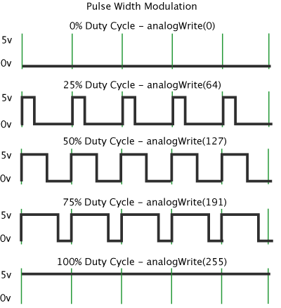
We programmed our LED to fade on and off using PWM and observed its behavior using the Oscilloscope.
// Fading LED code
int brightness = 0;
int fadeAmount = 5;

void setup() {
  pinMode(LED_BUILTIN, OUTPUT);
}

void loop() {
  analogWrite(LED_BUILTIN, brightness);
  brightness = brightness + fadeAmount;
  if (brightness == 0 || brightness == 255) {
    fadeAmount = -fadeAmount;
  }
  delay(30);
}
Using the Oscilloscope, we were able to see the voltage modulation and what the PWM signal looked like, and how the LED corresponds to that signal. We could adjust the view to examine the signal closely.

