Task 2: CNC Milling
- make (design+mill+assemble) something big (~meter-scale)
- extra credit: don’t use fasteners or glue
- extra credit: include curved surfaces
For this week, I would like to challenge myself to make a multipurpose, modular, and stackable storage for the lab. At the time of writing this (12/03), our CNC Machine is still under repair. I wasn’t so sure about the measurement for the storage… but what is amazing about parametric design is that you can just adjust the parameters afterwards.. so for now… I imagine this is a modular vinyl listening cabinet on wheels.
Inspiration


Design
Firstly I made my parameters

And then quickly get to sketching and extruding the different parts


As you can see, from the pictures above, I was using dovetail as the main joinery system. However as I presented this design to Neil, he mentioned that dovetail would require a specific router bit. Rico also suggested that I should go design with dogbones instead for the joinery mechanism because it’s easier that way. So why dogbones? Due to the cylindrical shape of CNC router bits, achieving perfectly sharp corners is not possible. As a result, joints should be designed with rounded corners to accommodate this limitation. This design not only addresses the tool’s limitations but also helps maintain continuous movement during cutting, which prevents overheating and extends the tool’s lifespan.
Joinery: Dogbone
I followed this tutorial to create my mortise and tendon mechanism
In fusion - I would suggest create a two-point circle and insert the diameter with bit value (6mm).

Create a 3mm (Bit Value/2) line that extends from the point of the mortise to the center of the circle. Make a 45 degree angle between the length of the mortise with the line.


Copy the circles to other mortises. Finish Sketch. Select all the faces - and then we will be cutting thorugh the material thickness (18mm).

This is how the result would look like


I originally designed a three stackable storage, however as our CNC machine was having it’s fair share of troubles, I decided to prototype one first. Me & Tafia had to find a commercial CNC cutting spot that would allow us to operate the machine.
CAM
CAM refers to software used to control machine tools and translate digital designs (created with CAD software) into specific instructions for the machines. This allows for automated and precise manufacturing of parts. Fusion has a CAM function that allows you to transition your design for manufacturing easily. To achieve that firstly let us move workspace from Design > Manufacture.

We want to Create Manufacturing Model so that we can easily lay out the different parts without ruining the assembled model we did in the Design workspace.

Edit your parts and lay them flat like on one sheet.


Create a new setup - we will be determining the work area of the parts that will be cut. Create a ‘stock’ area relative to your material size. Which in the case for ours is 1220 mm x 2440 mm with material thickness of 18.2 mm


Toolbit
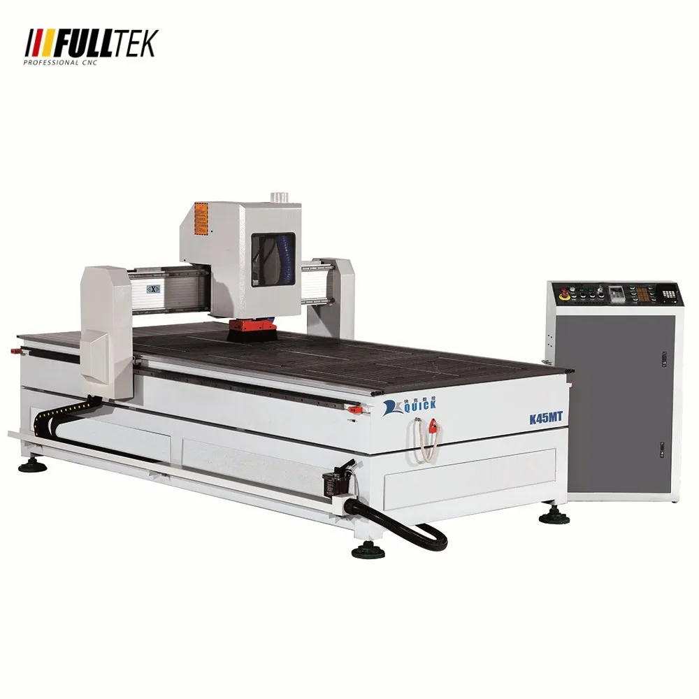
The commercial CNC cutting spot that we went to had their own recommended setting for their 6mm milling bit and their CNC Machine. This is their machine and milling bit specification
- K45MT Jinan QUICK CNC Router 1325
- Warrior Bit WDL632 6mm Solid Carbide End Mill Up Cut, Single Flute, 60L

When we want to cut choose the option 2D > 2D Contour.

In the Tool tab. Press Select Tool. We will need to create a custom tool bit and cutting data based on the specification of the milling bit and the machine. I got the following custom values the CNC shop normally uses and appropriate it into Fusion CAM’s cutting setting.
- Speed: 15,000 rpm (spindle speed)
- Feed Rate: 76mm/sec (defines the speed at which the cutting tool moves relative to the workpiece)
- Plunge Rate: 50mm/sec (feed rate applied to the Z-axis (vertical movement) of the CNC machine)
- Stepover: 2.4mm (cut width, or radial depth of cut, refers to the distance the cutting tool moves laterally between successive passes during a machining operation)
- Stepdown: 6mm (depth per pass)


Press Accept and all the values will be loaded automatically.
 .
.
Toolpath
In the Geometry tab - choose the edges of the model that will be cut. Include tabs to secure the parts and prevent the part from vibrating or moving excessively, ensuring accurate and clean cuts. Tabs provide stability especially for thin or intricate parts. Without them, the part could bend or warp under the cutting forces, compromising the final shape.


Finally at the Passes tab - it should automatically follow your toolbit setting.

Follow this setting at your own risk!!
This is a very aggressive setting. Ideally we would want to go for a more conservative setting to preserve the longetivity of the tools. The golden rule is 1/2 the diameter of the milling bit for the cut depth. However the depth pass is 6mm - which forces the entire cutting edge into the material. This makes the cutting process very quick but can put excessive strain on the tool, leading to accelerated wear, potential chipping, or even breakage. The harder the material property is - the slower and less cut depth we want to go with.
Our toolpath is now sorted. We can also simulate to see how the cutting job would look like. Fusion CAM predicted that with the following settings, my whole job can be completed in around 13 minutes. As mentioned in the warning above, the following setting is very very aggressive.


Now Export it as a GCode by right clicking on your toolpath > Post Processing. Fusion has a library filled with CNC machine settings and the CAM will adjust to the selected machine specification. However, I couldn’t find the machine that the shop uses in the library - so I went with the generic GRBL. While the generic GRBL post processor doesn’t offer machine-specific optimizations, it provides a basic framework for translating a toolpath into G-code that a GRBL-controlled CNC machine can understand.


Cutting
Test Cut
Since one of the challenge of the assignment was to create without fasteners or glue - an important aspect before wasting too many materials of your choice is to test out the joinery system first. I used two kinds of joinery for this storage box. Finger joints for the sides, tabs for the top and bottom part of the storage. An important thing to consider is that your joinery system will require ‘tolerance’ so there would be a ‘press fit’. Tolerance acts differently on different materials and material thickness. In Fusion, I inserted new parameters, ‘Tolerance’ & ‘Finger Joints Tolerance’. Create an offset on the tabs and the fingerjoints and input the parameters. That way when you have to do your tests - you can just quickly change the value without going through manual edits.


Initially I wanted to use plywood for the storage however, the CNC place doesn’t supply one. They recommended me to use a High Moisture Resistant board instead. HMR board is a type of engineered wood panel that’s specifically designed to handle high humidity and moisture environments. They are made from wood particles or fibers that are bonded together with a special resin that makes them resistant to water absorption. They are in a way similar to MDF board - but are more resistant to moisure compared to MDFs. Unfortunatly I had to order an 18mm HMR Board as they didn’t have it in stock. So I did my test cuts on an old 18mm MDF Board that they have lying around. What I found is that for
- tabs = 0.2mm tolerance
- finger joints = 0.4mm tolerance (0.2mm tolerance for each side so 0.2 + 0.2 = 0.4)


When I received my HMR Board, the 0.2mm tolerance fits tightly, however 0.4 finger joints were way too loose - so I had to quickly redesigned and reduce the finger joints tolerance to 0.2mm. By changing the value in the parameters. Here were the results.
- tabs = 0.2mm tolerance
- finger joints = 0.2mm tolerance (0.2mm tolerance for each side so 0.1 + 0.1 = 0.2)


Final Cut
After finding out the right tolerance precise for my needs - I had the boards laid out and cut. The real cut took about 15 mins!

Assembly
The cut result came out smoothly. I just needed to lightly sand the parts to remove any debris. The assembly part took a bit of time because the mortises and tendons were very “press-fit”. It wasn’t that difficult to assemble. Just abit annoying because how tight the tabs and joints are - but in the end everything came out nicely. Ideally you would want to use a mallet to fit the mortises into the tendons… they didn’t have a mallet lying around so I improvised, using a hammer, cloth, and a small block of wood.


