Week 4. Electronic production
This week I will replicate the Quentorres created by Quentin Bolsée and redesigned by Adrián Torres. I will try to make it with some different methods that I have never used before.
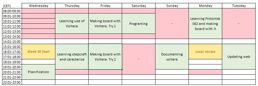
This week, the week assignments were:
characterize the design rules for your in-house PCB production process
make and test a microcontroller development board
extra credit: personalize the board
extra credit: make it with another process
Group assignment
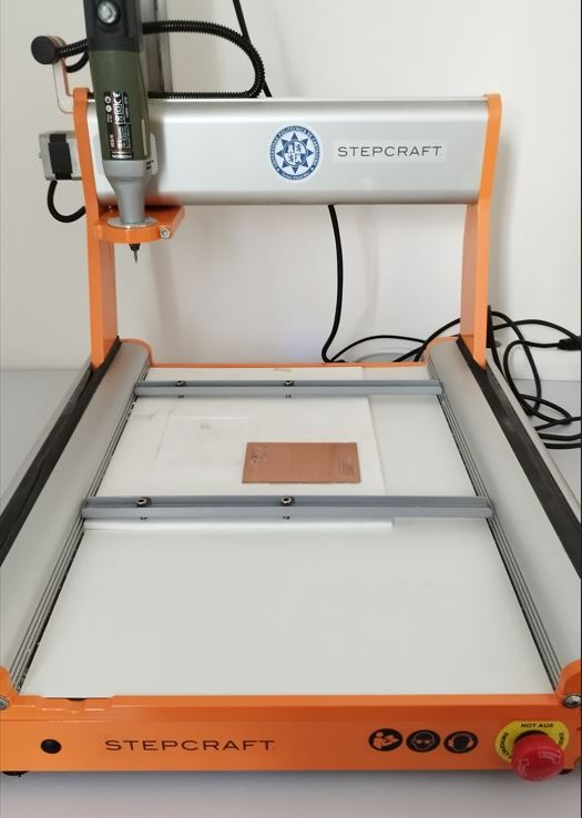
I caracterized Stepcraft 420. It is a multifunctional machine with different tools to work with milling, 3D painting and laser cutting.
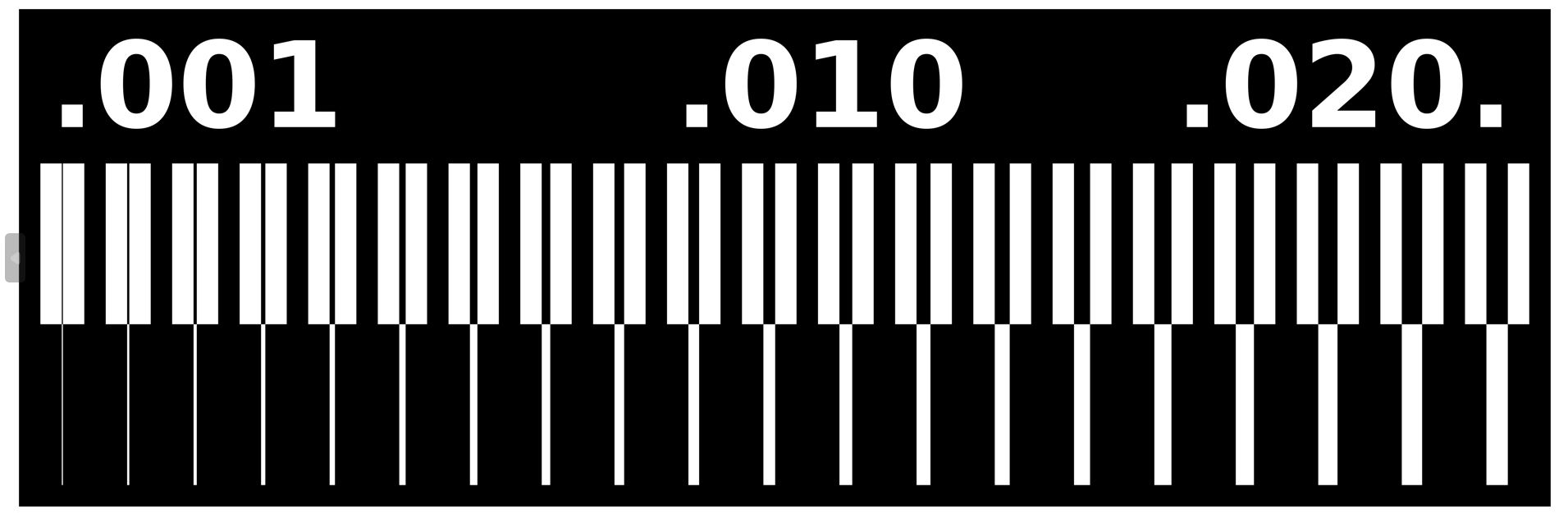
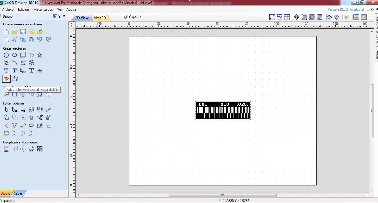
I take the png of the following image and used cut2d
After creating a new project, and putting the material configuration I converted the design bitmap to vectors
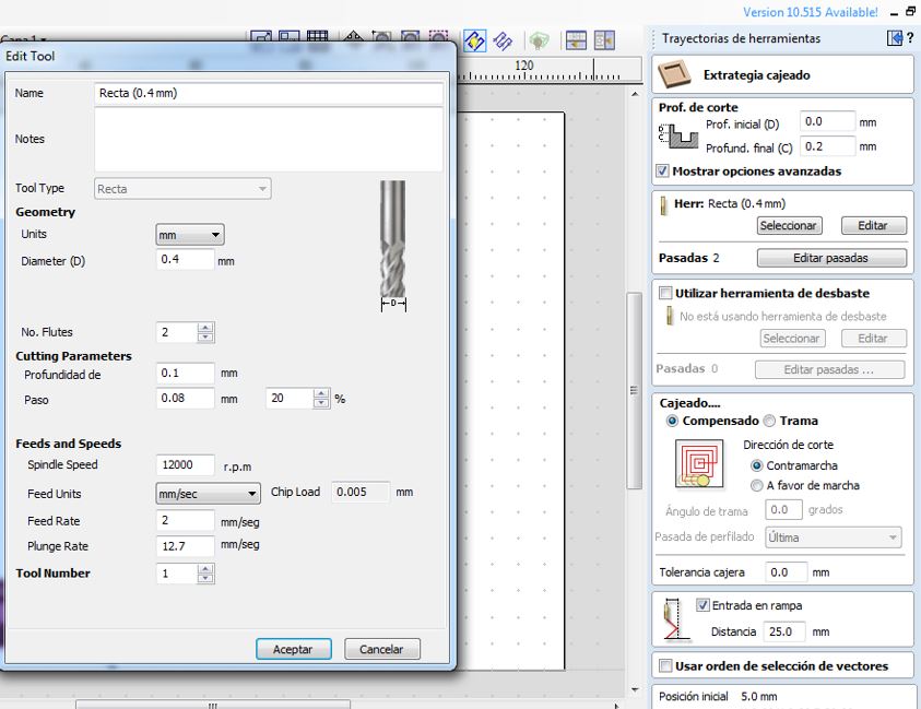
With PCB in place, I set a pocket operation.
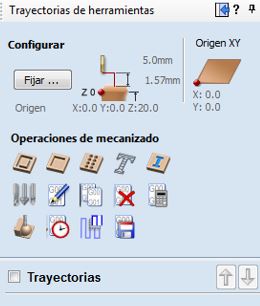
I select feed sepeed: 2mm/s depth of cut 0.2mm sprindle speed 12000rpm depth of cut final 0.2mm, and then calculate track.
Save operation and open UCCNC software
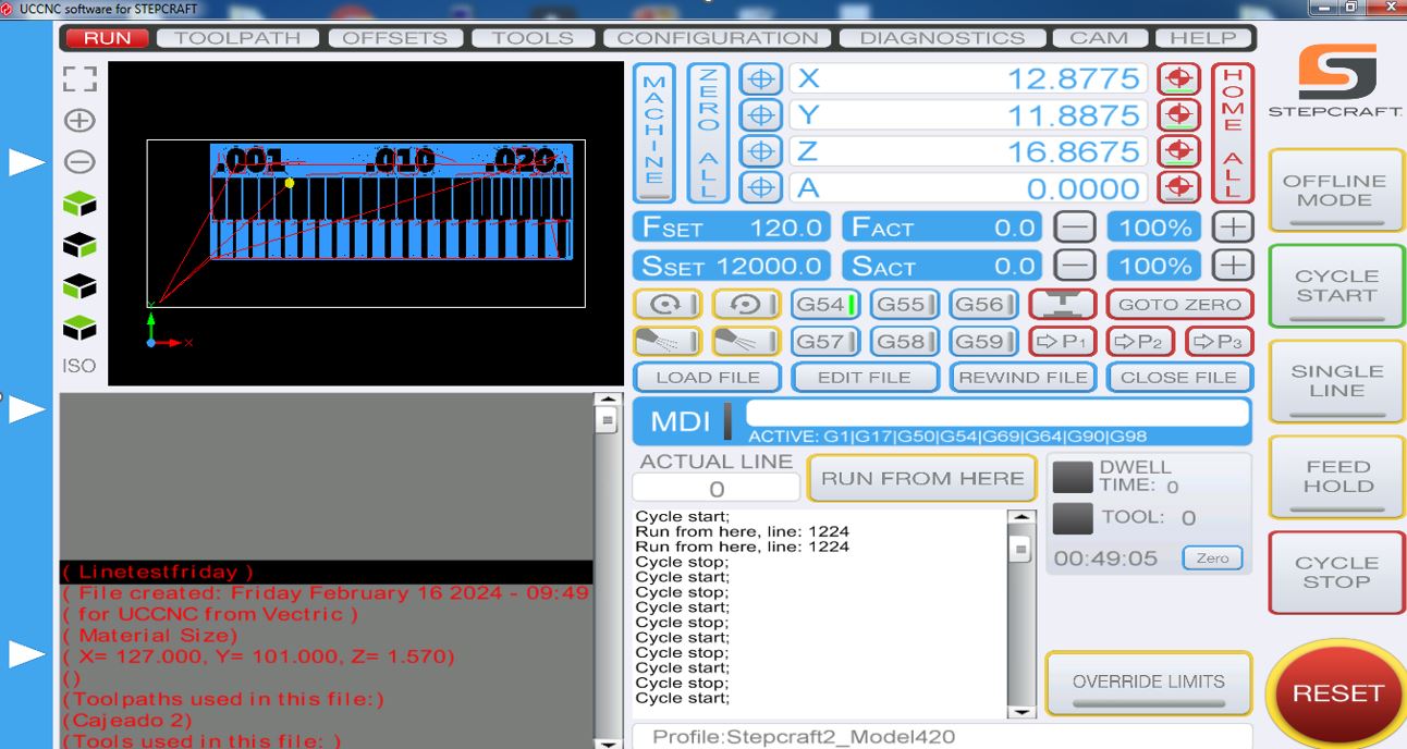
First of all, I had to zero all, placing manually with keyboard shortcuts (arrows to move x & y, pg up and pg down z axis), and press zero all in blue. Once its done press Cycle start.
And I got this caracterization board, in which we can see its unleveled.
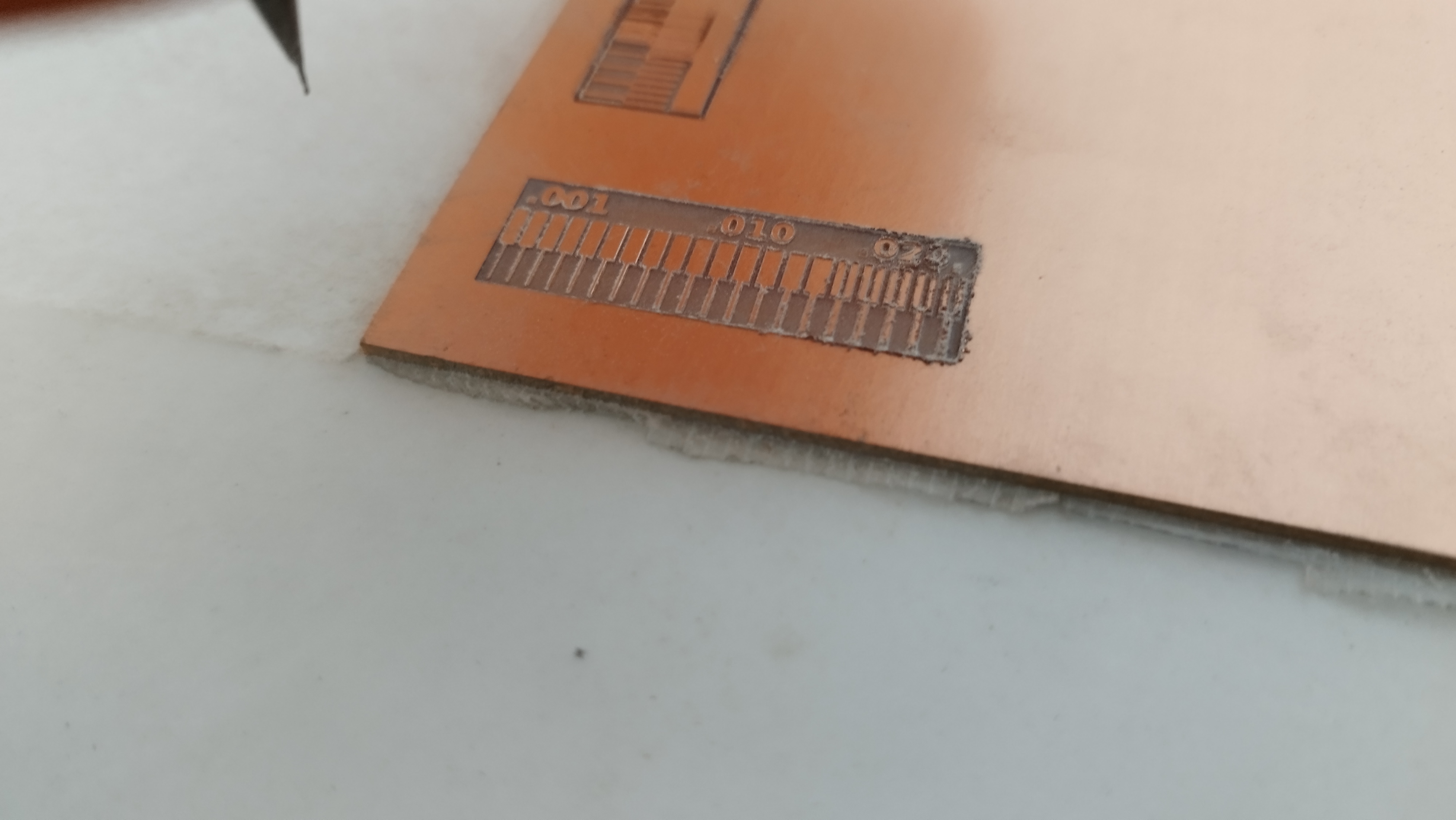
So I decided to use ProtoMat S62 to the Quentorres board, because It was being used and we know it was leveled and properly calibrated.
Individual assignment. Make and test a microcontroller development board (and extra using another process)
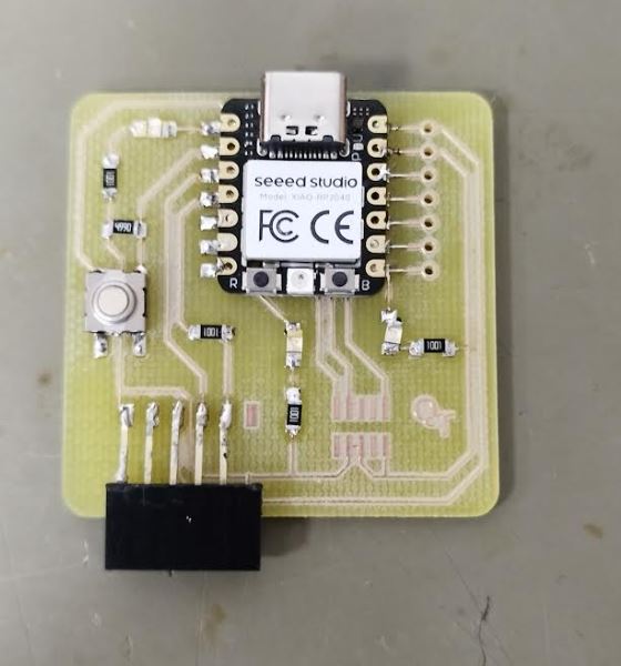
QUENTORRES is the development board to make this week. Next image is about components needed to make it.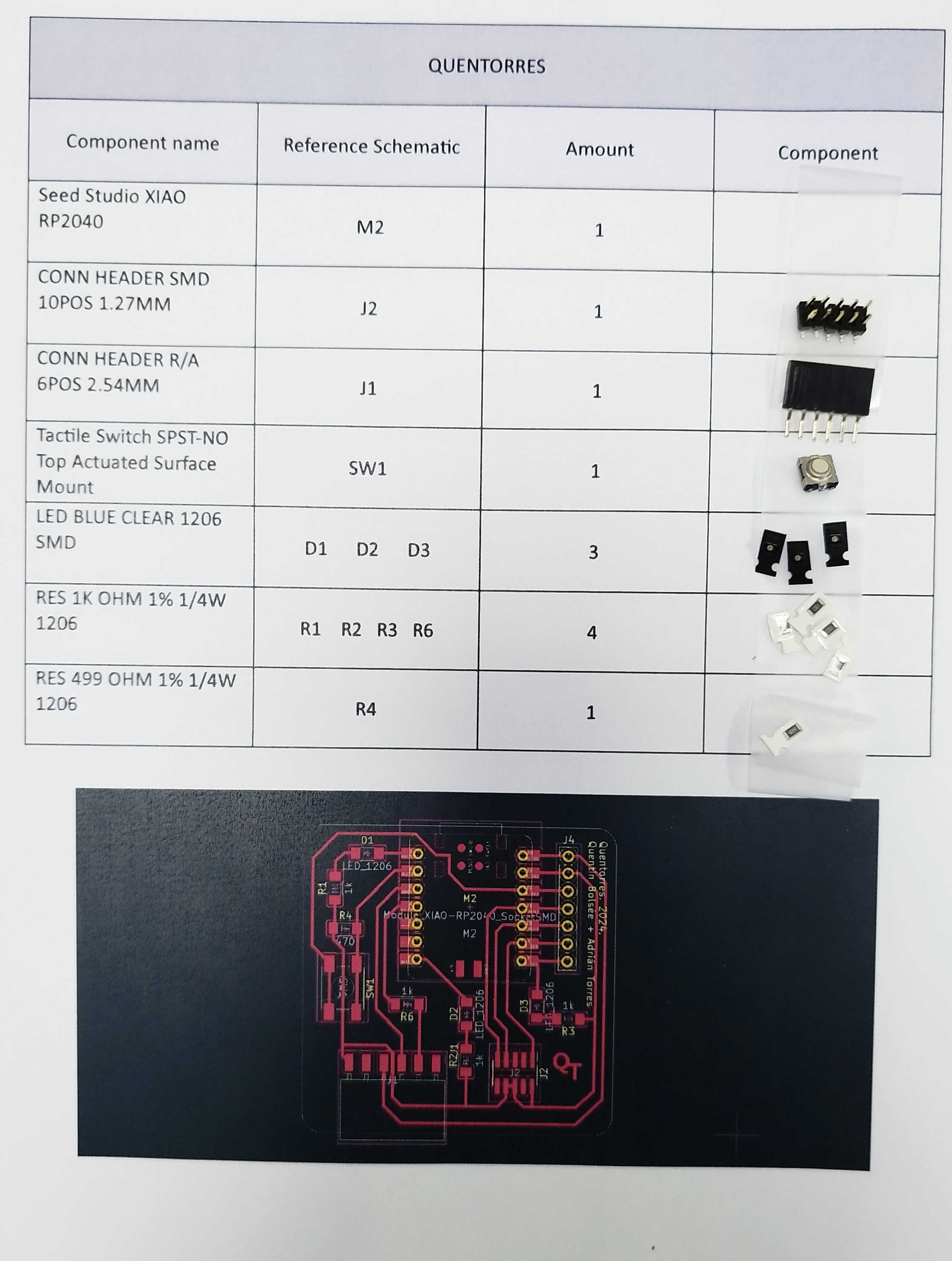
I tried to make it in three diferent machines: Voltera, Stepcraft and ProtoMat S62.
First, I used the Voltera (with no success).
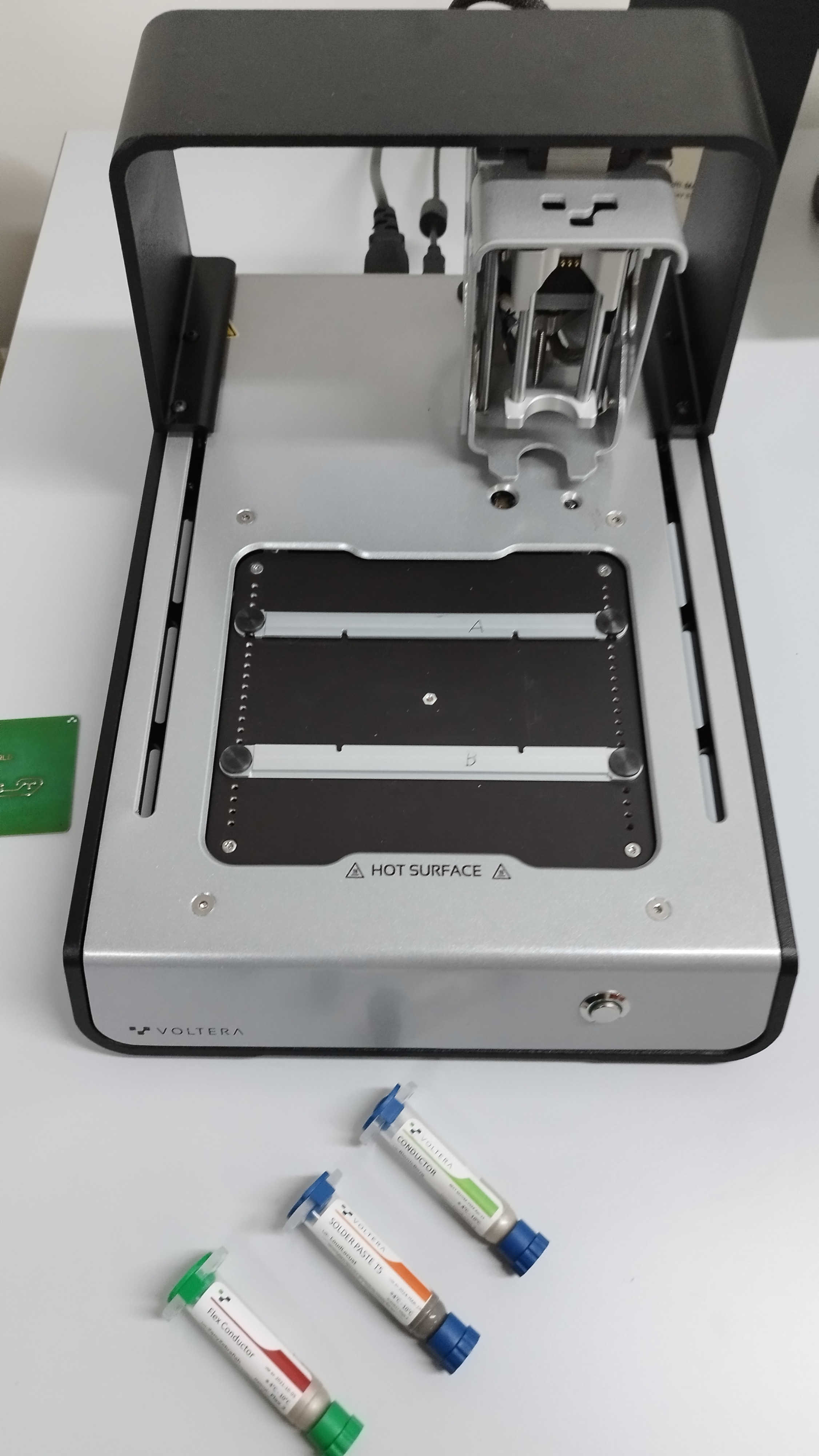
This is a circuite printer, that uses conductive ink to make the circuit, and solder paste to solder, but it can also drill.
I had a problem with this machine and that is that despite the fact that it said that 180ºC had to be applied for hand soldering, at that temperature the conductive ink peeled off. Besides, when I press a bit to connect the usb-c, the micro went off.
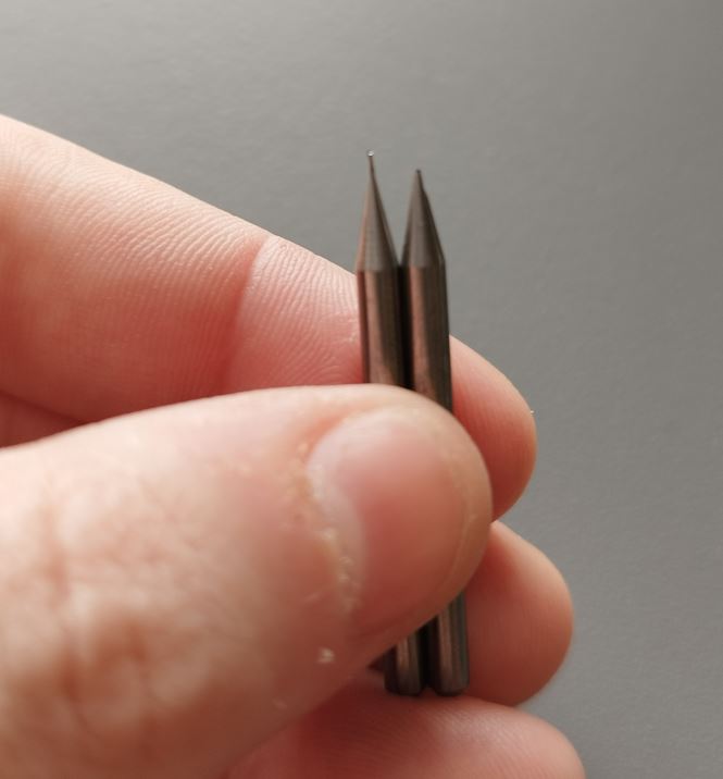
Then, I tried with stepcraft but the drill broke due to poor levelling of the bed.
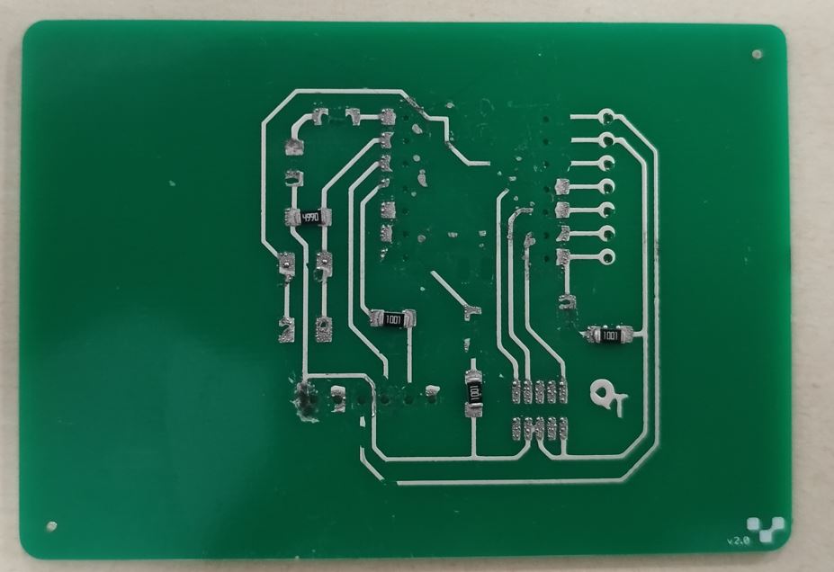
Finally, I made the board with protomat S62, got better results in less time.
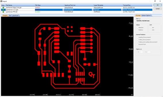
To make it with Protomat62, two software packages are used: CircuitCAM and BoardMaster. Firstly, I used CircuitCAM where I imported the Gerber file.
Then in tool path I pressed insulate where I could choose which tool it will be used.
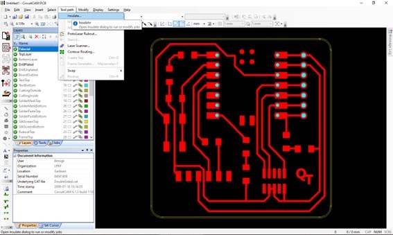
Now contour routing will calculate the routing.
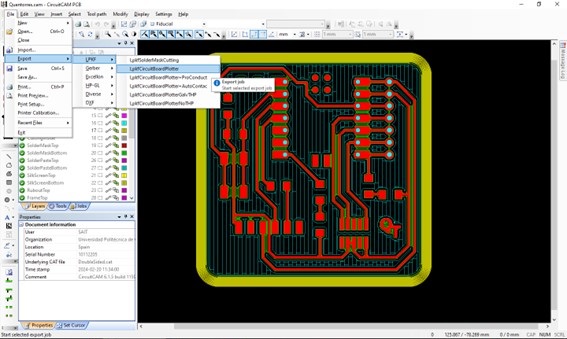
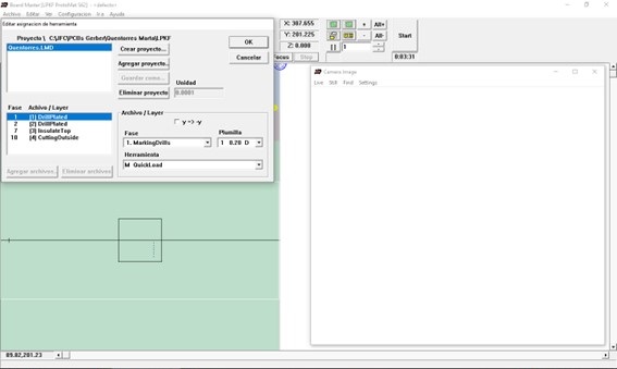
Finally save it and import to the BoardMaster software, where I can select what tools are in the machine and the step by step it will do.
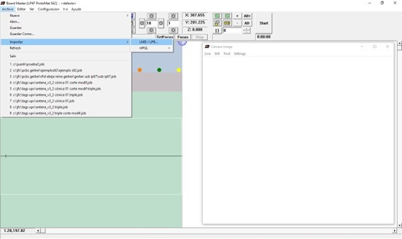
Finally, I select the desired step and press start.
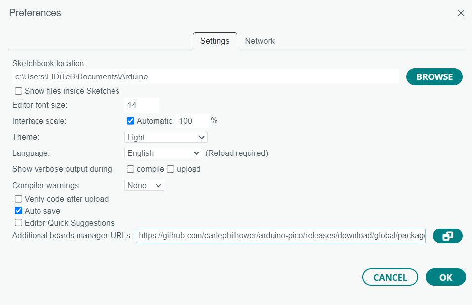
Then I programmed the blink ussing the example and configuration in wiki seeed studio.
Download and Install the latest version of Arduino IDE according to your operating system, windows for me. And launch it. In file -> preferences, paste the link https://github.com/earlephilhower/arduino-pico/releases/download/global/package_rp2040_index.json Navigate to Tools-> Board-> Boards Manager..., type the keyword "RP2040" in the searching blank. Select the lastest version of "Raspberry Pi Pico/RP2040" and install it.
Conclusion
Although it may seem obvious, use each machine for its specific function. If I know something go properly, do that way, only improvise if there is time.