Basic Concepts of Molding and Casting
Molding is the process of manufacturing by shaping liquid or pliable raw material using a rigid frame called a mold or matrix. This itself may have been made using a pattern or model of the final object. The liquid hardens or sets inside the mold, adopting its shape. A mold or mould is a hollowed-out block that is filled with a liquid or pliable material such as silcine rubber, plastic, glass, metal, or ceramic raw material. A mold can also be made of wood, MDF carved on a CNC milling machine. A mold is the counterpart to a cast.
Molding is a technique through which a material, often plastic, but also metal, rubber, or powder mixtures is shaped on the outline of a die or mold. There are many different techniques for molding materials, just as there are many different applications for each process. Moulding boxes are special purpose boxes that are designed for use in moulding systems where the demand of high pressure moulding and high production rates (from a fully automated system) require a box designed & machined to exacting tolerances.
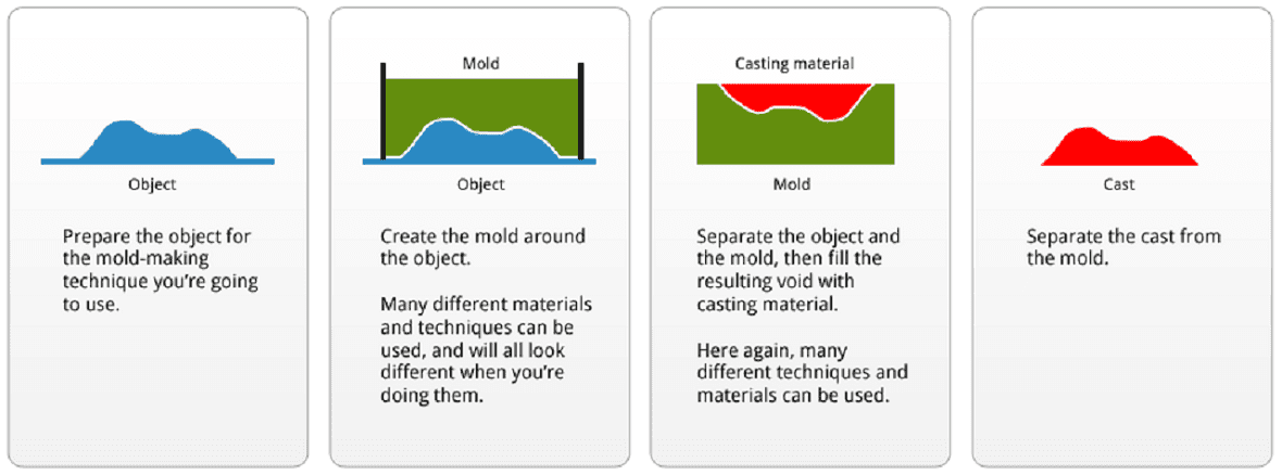
Casting is a manufacturing process in which a liquid material is usually poured into a mold, which contains a hollow cavity of the desired shape, and then allowed to solidify. The solidified part is also known as a casting, which is ejected or broken out of the mold to complete the process.
Read more-Molding and
Sprue, Runners and Gates
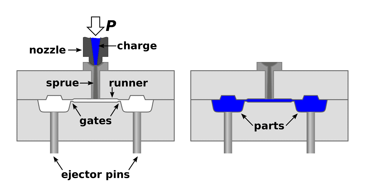
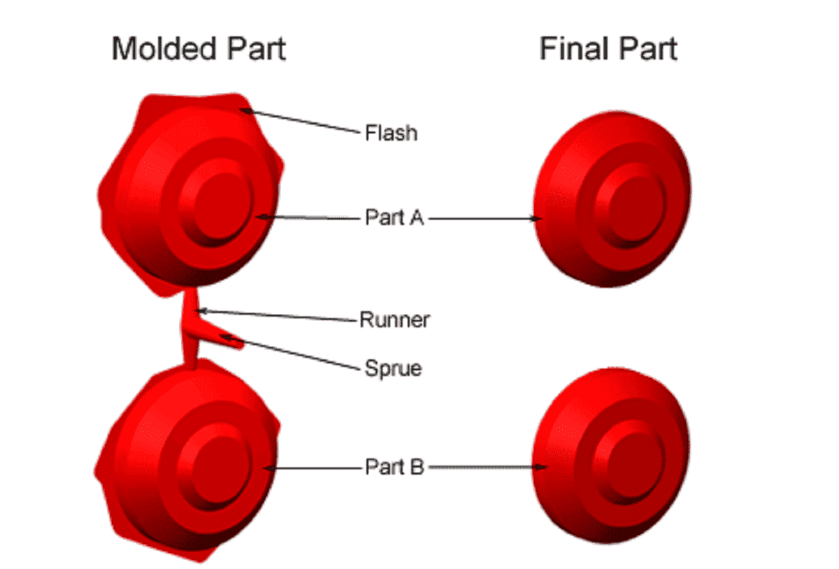
Sprues and runners are integral components in the manufacturing process, particularly in injection molding, where molten materials like plastic or metal are injected into molds to create various products. Think of them as the highways that guide the flow of the molten material into the mold cavity. The sprue serves as the main entry point, resembling a large funnel through which the material is poured into the mold. Meanwhile, runners are like smaller channels branching out from the sprue, directing the material to different sections of the mold, especially when multiple parts are being produced simultaneously. At the point where the material enters the mold cavity from the runner, it forms what's known as the 'gate.' Once the material cools and solidifies in the mold, the excess material in the form of sprues and runners needs to be removed to reveal the final product. Interestingly, in certain applications such as small plastic models, these leftover bits are repurposed as a packaging method, showcasing a clever utilization of what would otherwise be considered waste material.
Vents
Vents play a crucial role in the injection molding process by allowing air to escape from the mold cavity. Before the molten material is injected, there's a lot of air trapped in the flow path and cavity. When the material enters rapidly, it's important to get rid of this air quickly so that the plastic can fill up all the space properly. Additionally, as the material cools and solidifies in the cavity, a vacuum forms between the product and the cavity wall, so air needs to enter the mold to aid in ejection. Without vents, the trapped air would compress as the plastic pushes it out, leading to burning issues. Vents need to be sized just right—large enough to let air out but not so big that the plastic leaks out, causing flashing. They should ideally be located at the end of flow paths or where these paths come together. It's also essential to keep vents clean to prevent clogging, ensuring that air can still escape effectively.

Parting lines and Flashing
A parting line is where the two halves of a mold meet, creating a separation line on the finished part. This line marks the boundary between the areas of the mold that form the top and bottom of the part. While it can be a simple flat surface on straightforward parts, it often follows the contours of the part's shape, including its outer features. Parting lines can also occur where different parts of the mold meet, such as with side action pins or tool inserts. They're unavoidable and essential in molding processes. When designing a part, it's important to consider that molten material tends to flow toward the parting line because it's the easiest path for air to escape.
Flash, on the other hand, is excess material left on the finished part due to the seam of the mold. When material enters the mold, it can seep slightly into this seam, leaving behind a thin layer of material when the part is removed. While it's generally easy to remove, it's crucial to consider during mold design to ensure it doesn't affect the functionality or appearance of the final product, especially in parts with tight tolerances or areas requiring seals. Experienced mold designers work to minimize and hide seam lines, collaborating with product designers to achieve the desired outcome.
DAY-03
Group Assignment
Click here to read more about group asignment.
Individual Assignment
Onjectives of Individual Assignment:
1. Design a moold around the stock and tooling that you will be using
2. Mill it(rough cut + three-axis finish cut)
3. Use it to cast parts
1. Designing a Positive Mold
I wanted to make Flushed face emoji using molding and casting process. So, I used SolidWorks CAD software to design my mold. Here are the steps of designing positive mold-
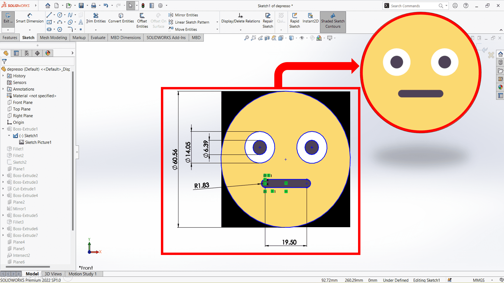
Firstly, I download image of Flushed emoji from google and imported it into SolidWorks CAD software to draw basic design of my workpiece. Then, I designed basic design of my emoji by tracing lines of image and give it proper dimensions.

Here, I used "Boss-Extrude" feature to extrude my emoji by 10mm.

I used "Fillet" feature to give more attractiveness to my emoji.

Again, I used "Boss-Extrude" feature to extrude eyes of my emoji.

Here, I created a outer box and at the centre I have placed my workpiece to make positive mold of my workpiece.

I drew circles at each corner of the box and used "Cut-Extrude" feature to make press fit joint which helps during molding process.
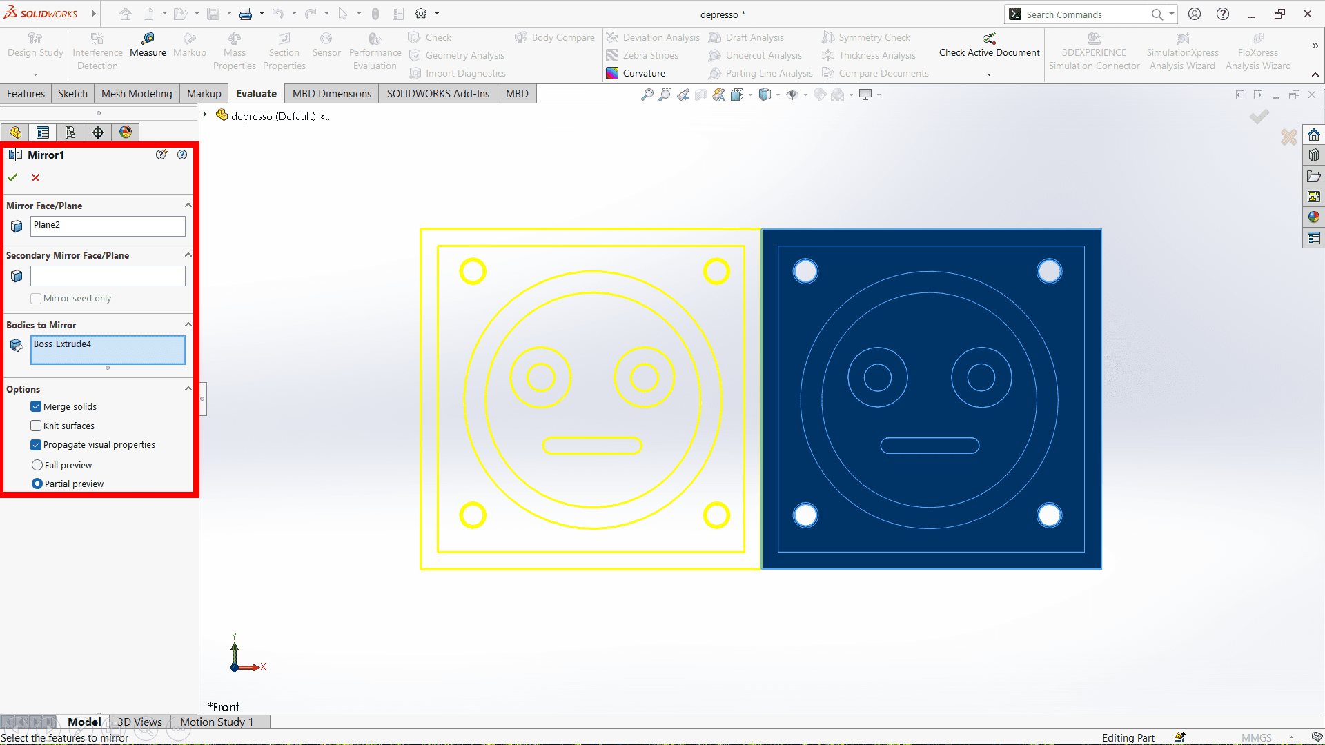
Here, I used "Mirror" feature to create exact opposite side of positive mold.
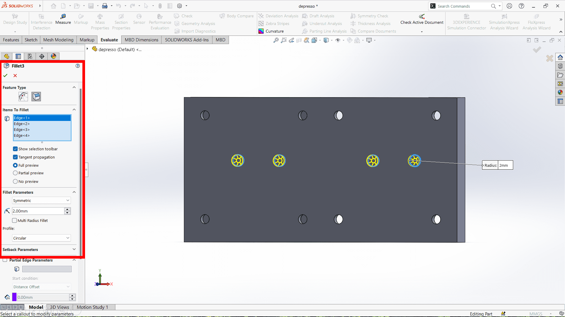
Again, I used "Fillet" feature to make my workpiece more attractive.
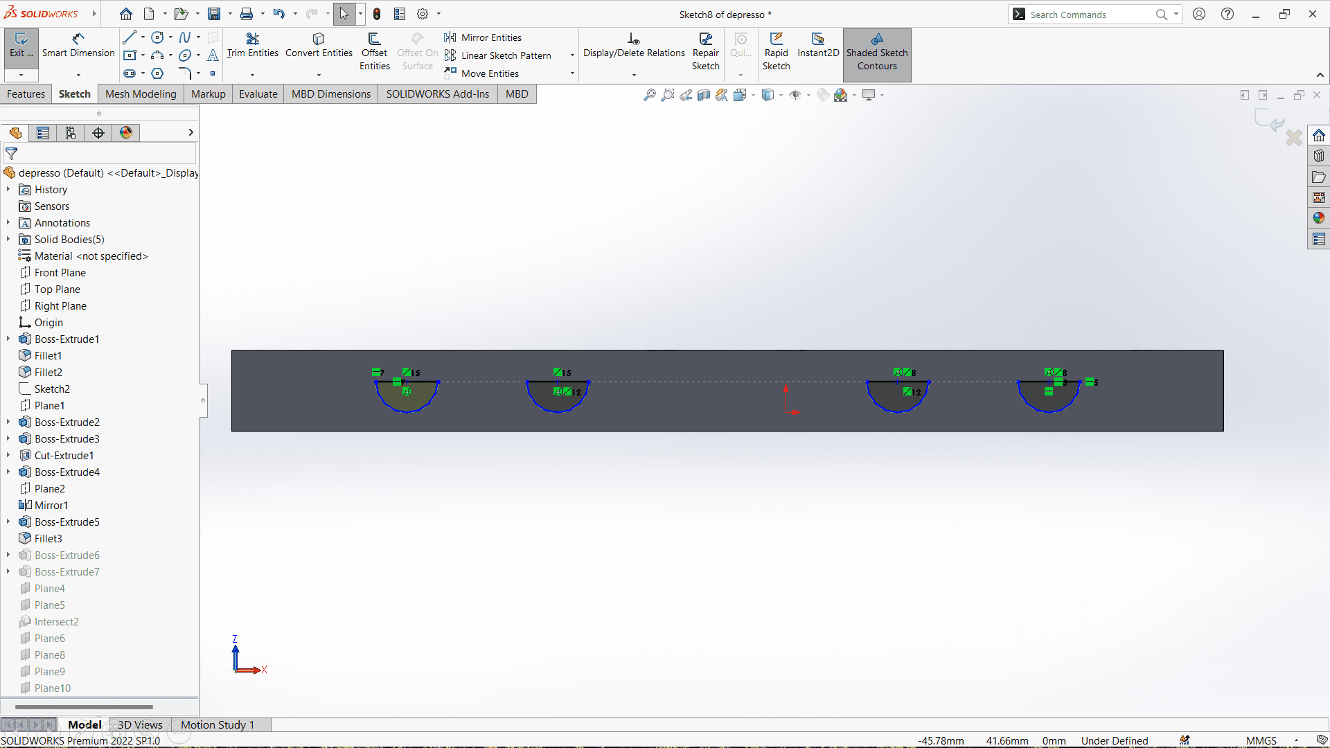
I drew basic design of sprue and runner at the bottom face of positive mold for pouring material and removing air bubbles.

Here, I used "Boss-Extrude" feature to design sprue and runner which helps during molding process.

Finally, positive mold is ready💃💃 Now, it is ready for the 3D printing. Here, I have used Creality Slicer software to generate GCode of my STL file which imported into 3D printer for 3D printing.
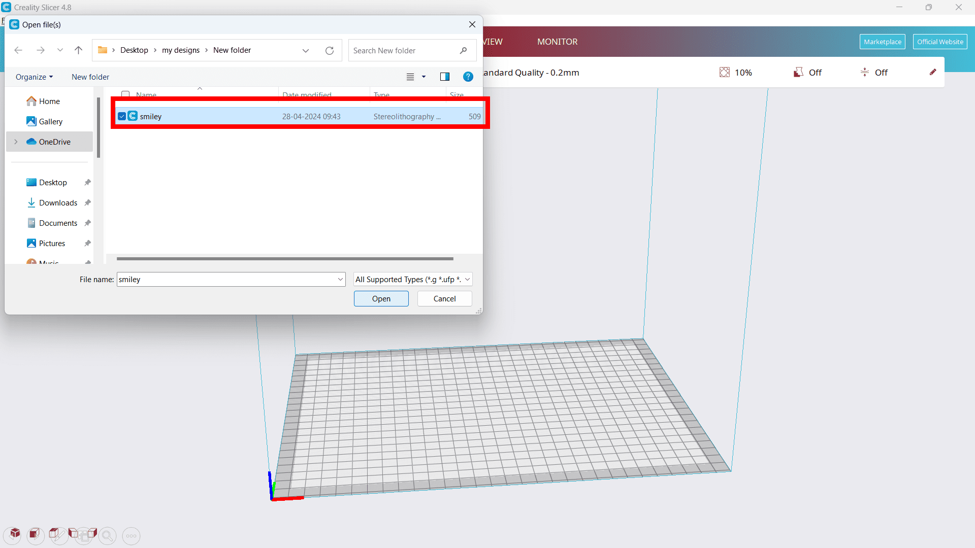
Firstly, import STL file into Creality Slicer by clicking on import file option and then select STL file and open it.
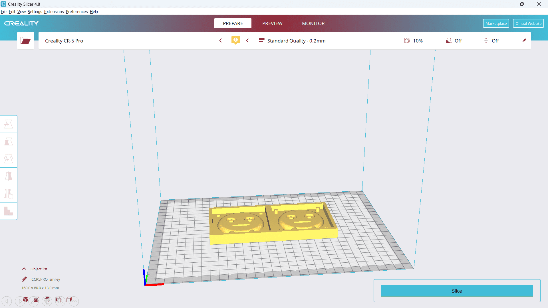
reaarange and set required parameter such as infill, nozzle temperature, bed temperature,etc.

By slicing it, I got GCode file of my STL file along with time required to complete whole workpiece using 3D printer.

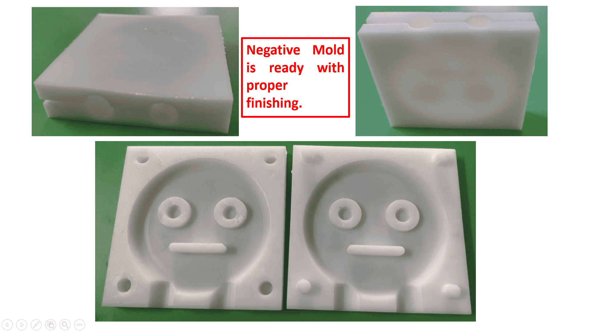
Here, I got the satisfied output with proper finish. Now, positive mold is ready. With the help of positive mold I started developing negative mold of my workpiece using molding process.
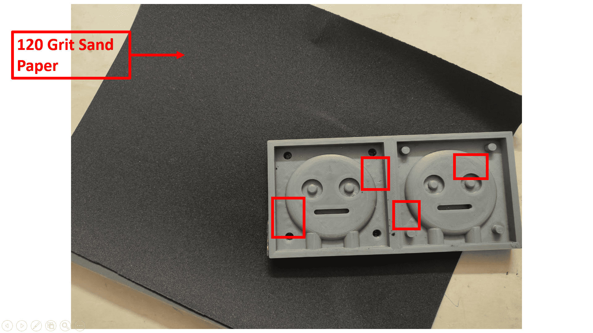
Before starting to make negative mold, I observed some irregular surface in some portions of the mold. To remove that irregular surface and to make smooth surface finish, I used 120 grit sand paper.
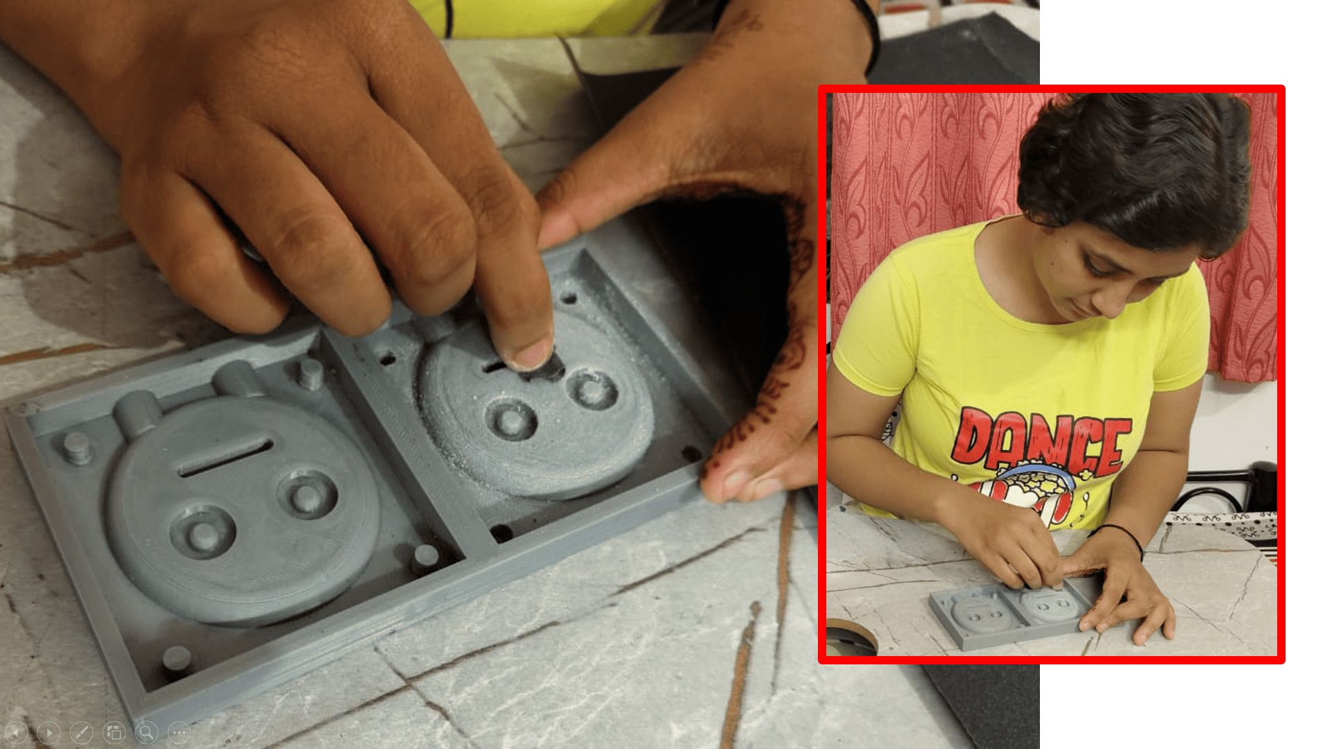
Here are some glimpse while rubbing the irregular surface of positive mold to make it smooth for better finishing of negative mold.

And here I got the output that with the help of sand paper I got the smooth surface finishing of positive mold.
2. Designing a Negative Mold
To make negative mold, I have used RTV2 Silicone rubber - 15C white material in 1:20 proportion. Firstly, I calculated exact amount of material which I have to use and then converted it into 1:20 proportion.
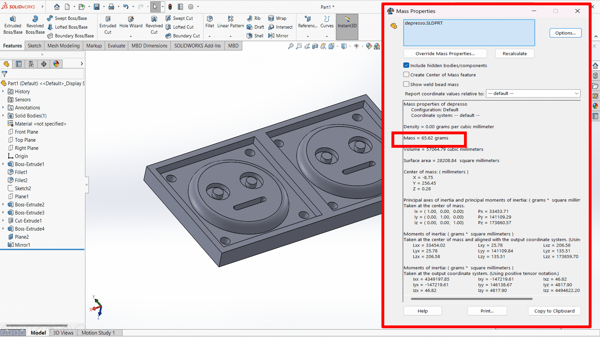
Here, I calculated the mass of my positive mold as 65.62 grams.

I used RTV2 Silicone Rubber - 15C white material to make my positive mold in the proportionn of 1:20.


Finally, I got my positive mold to make thee final object. Now, I used Forticast ERS LV material for my final object in the proportion of 2:1.
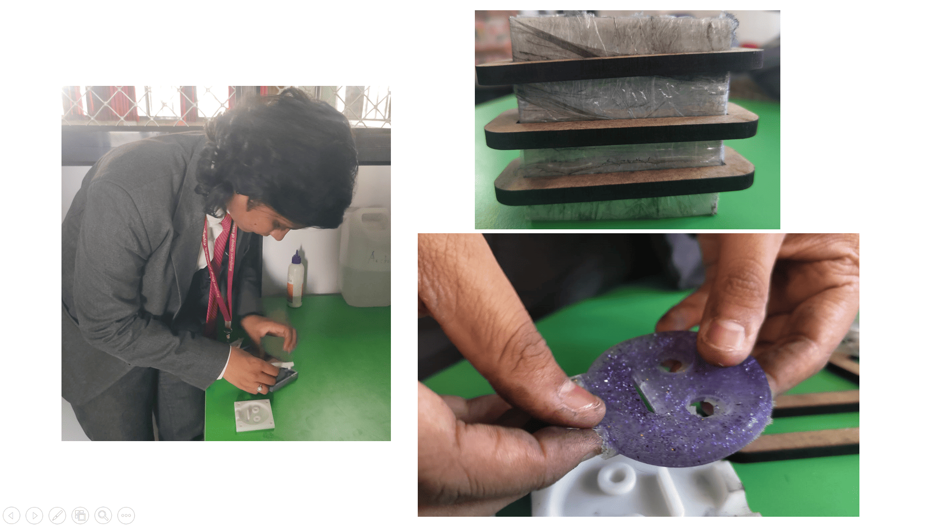
Finally, I got the output!