Starting with some basic concepts regarding Embedded Programming for better understanding.
Architectures
There are two types of architectures- (a) Von Neumann Architecture and (b) Harvard Architecture
1. Von Neumann Architecture
The Von Neumann Architecture is also known as Von Neumann Model or Princeton Architecture was proposed by John Von Neumann, a Hungarian-American mathematics and physicist in the 20th centuary. Von Neumann Architecture refers to a design model for computers where the processing unit, memory and input-output devices are interconnected through a single, central system bus. The core concept of this architecture is that it has one data path or bus to treat both instructions and data uniformly. This means that the same memory and processing resources are used to store and manipulate both program instructions and the data being processed. This design greatly simplifies the structure and operations of a computer, making it easier to understand and implement.
There are four main components withing the Von Neumann Architecture and they are work together to enable processing, storage and communication within the computer system. They are-
Central Processing Unit(CPU)- The part of a computer that carries out instructions and performs arithmetic, logical and control operations.
Memory- A place where the computer stores and retrievs data and instructions. Memory is divided into two types includes Primary Memory(Random Access Memory-RAM) and Secondary Memory(Hard disk drives).
Input-Output Devices- Components responsible for interfacing the computer with the external world. Examples like keyboard, mouse, printer, monitor,etc.
System Bus- A communication pathway that connects the CPU, memory and I/O devices to enable data and control signals to flow between these components.

Features of Von Neumann Architecture
1) Unified memory structure: Both instructions and data are stored together in the same memory.
2) Sequential instruction processing: Program instructions are executed one after another in a linear sequence.
3) Shared system bus: Components are interconnected through a central communication pathway, allowing for efficient communication and coordination.
4) Modularity: The architecture is suitable for a wide range of computer system, from simple microcontrollers to complex supercomputers by scaling memory and processing capabilities.
Real time examples of Von Neumann Architectureare ENIAC(Electronic Numerical Integrator and Computer), EDVAC(Electronic Discrete Variable Automatic Computer), IBM 701, Intel 4004,etc.
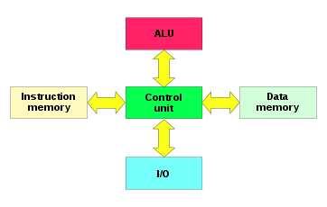
2. Harvard Architecture
Harvard Architecture is a computer architecture that separates the storage and handling of instructions and data using separate memory units and buses for each. This separation provides numerous benefits, including faster execution of instructions and improved overall performance. It enables independant caching of instructions and data. The main components of Harvard Architecture are Instruction memory, data memory, instruction fetch unit and data read-write unit.
Features of Harvard Architecture
1) Separate instruction and data memory units, which store program instructions and data separately.
2) Separate buses for reading instructions and data. enabling simultaneous access to both without any conflict or delay.
3) Faster processing of instructions due to the reduced chance of pipline stalls caused by resource conflicts.
4) Cache memory optimisation, which allows caching of instructions and data independently.
Real time example of Harvard Architecture are digital signal processors, microcontrollers, application-specific integrated circuits, FPGA based processor, etc.
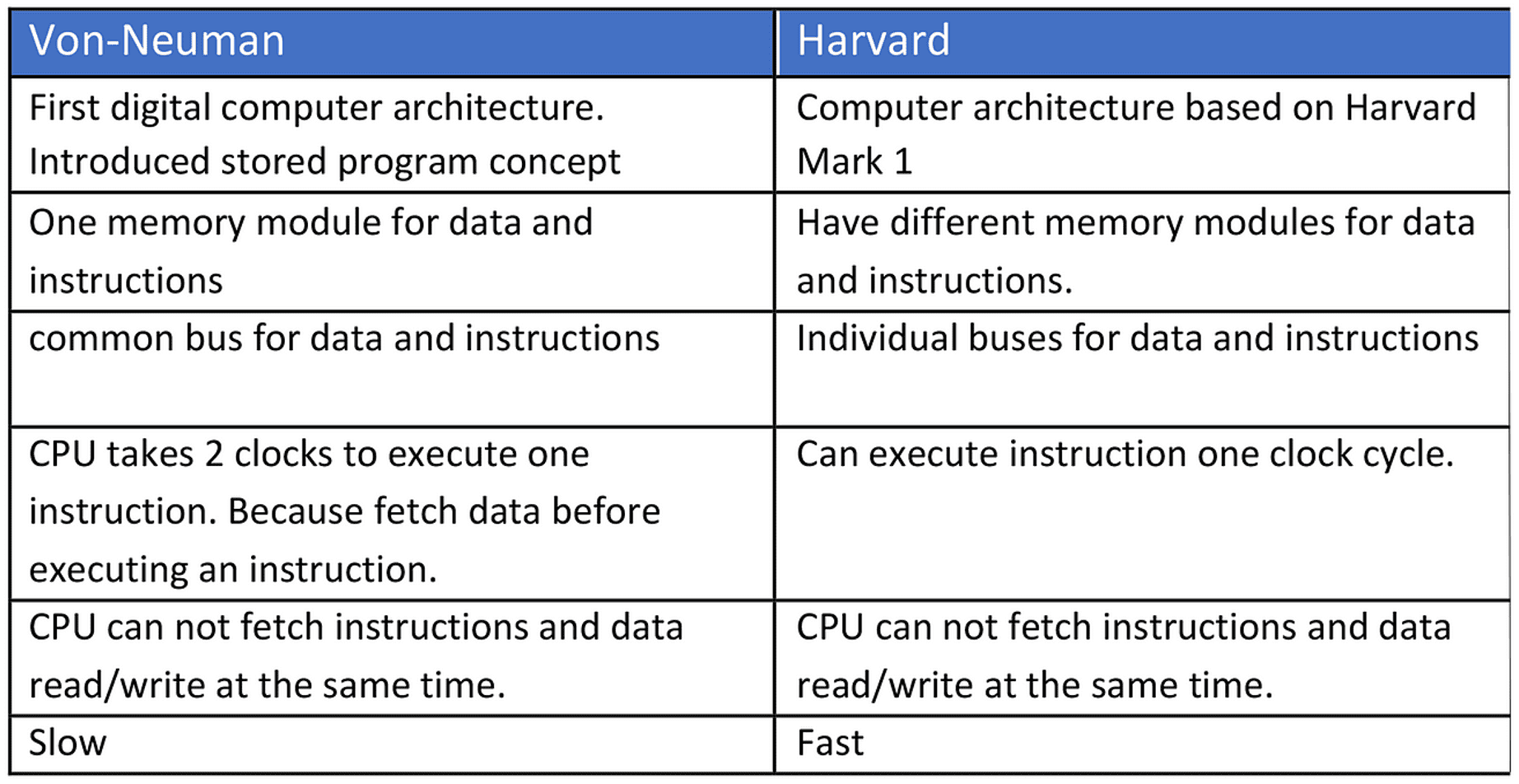
Difference between Von Neumann and Harvard Architecture
Another two types of computer architecture used to design the microprocessors are CISC and RISC in the computer.
What is CISC?
CISC referred as Complex Instruction Set Computer, characterized by a large number of machine instructions, some operating with data in registers and others directly with data in the system's memory. It is mostly used in automation devices. It is basically a computer in which individual instructions may perform many operations and take many cycles to execute. It is used to minimize the number of instructions per program, sacrificing the number of cycles per instruction.
What is RISC?
RISC referred as Reduced Instruction Set Computer, is a type of microprocessor architecture that utilizes a small, highly-optimized set of instructions, rather than a more specialized set of instructions often found in other architectures. Basically, it is a microprocessor that is designed to perform a smaller number of computer instruction types, so it can operate at a higher speed, performing more millions of instructions per second.
Difference between CISC and RISC

Microprocessor
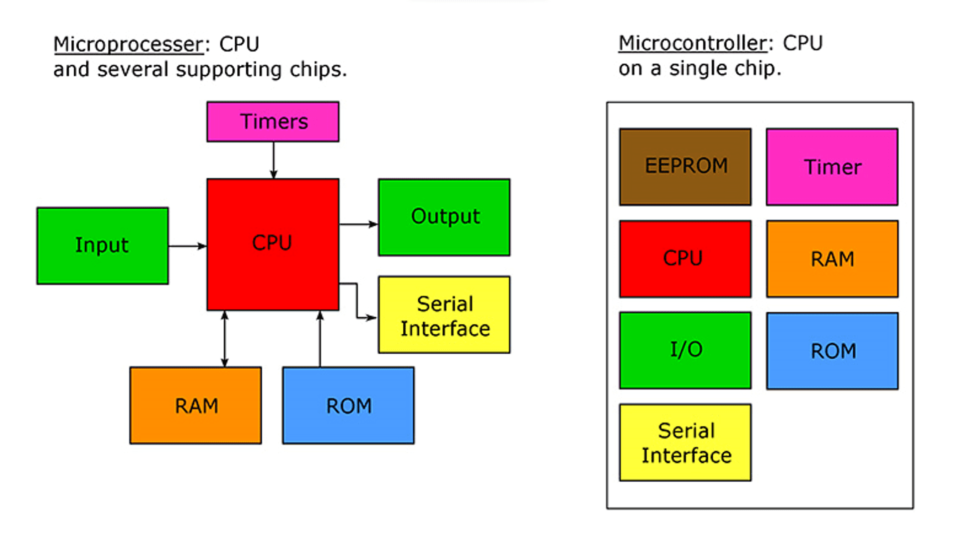
A microprocessor is a computer processor for which the date processing logic and control is included on a single integrated circuit(IC), or small number of ICs. It contains the arithmetic, logic and control circuitry required to perform the functions of a computer's central processing unit(CPU). It can function as the brain of a personal desktop computer. It is used to performs arithmetic and logical operations, provides temporary memory storage and times and regulates all elements of the computer system. It is a programmable, multipurpose, clocl driven, register based electronic devices that reads binary instructions from a storage device called memory, accepts binary data as input and processes data according to those instructions and provides results as output.
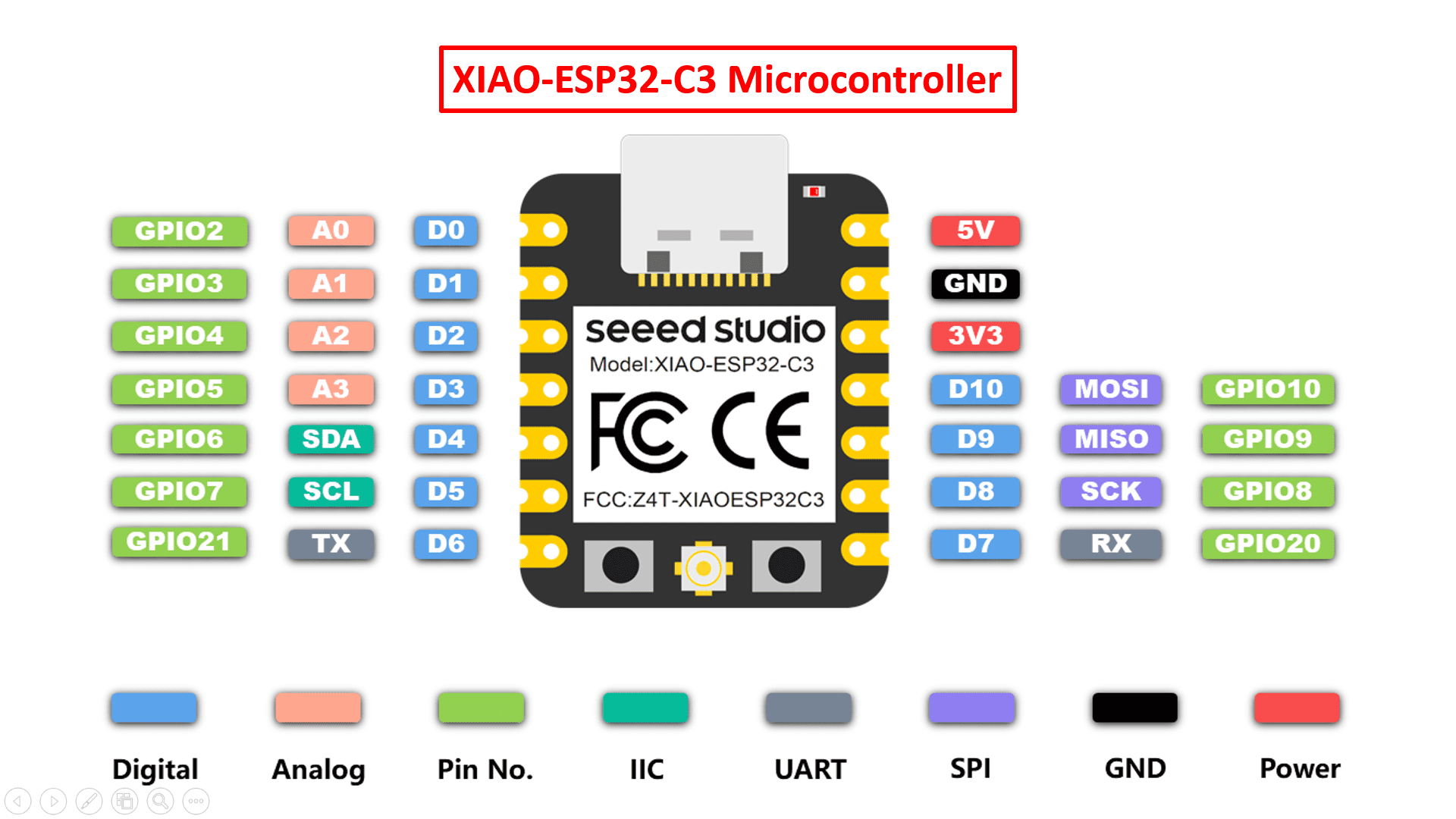
Microcontroller
A microcontroller is a compact integrated circuit designed to govern a specific operation in an embedded system. It includes a processor, memory and input/output peripherals on a single chip. It is basically manufactured to control the functions of embedded systems in office machines, robots, home appliances, motor vehicles and number of other gadgets. It is so called microcontroller because this device comprises of transistors which are small in size. A microcontroller is embedded inside of a system to control a singular function in a device. It does this by interpreting data it recieves from its I/O peripherals using its central processor. The temporary information that the microcontroller receives is stored in its data memory. These are used in a wide array of systems and devices. Devices often utilize multiple microcontrollers that work together within the device to handle their respective tasks.
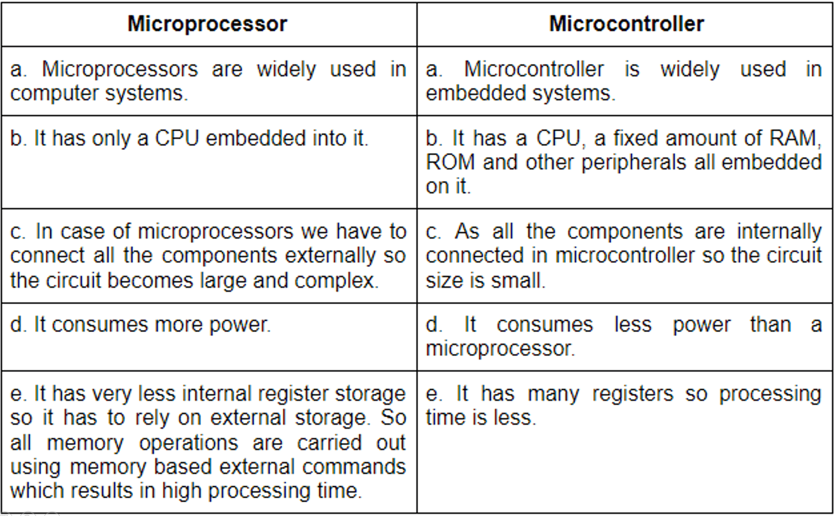
Difference between Microprocessor and Microcontroller