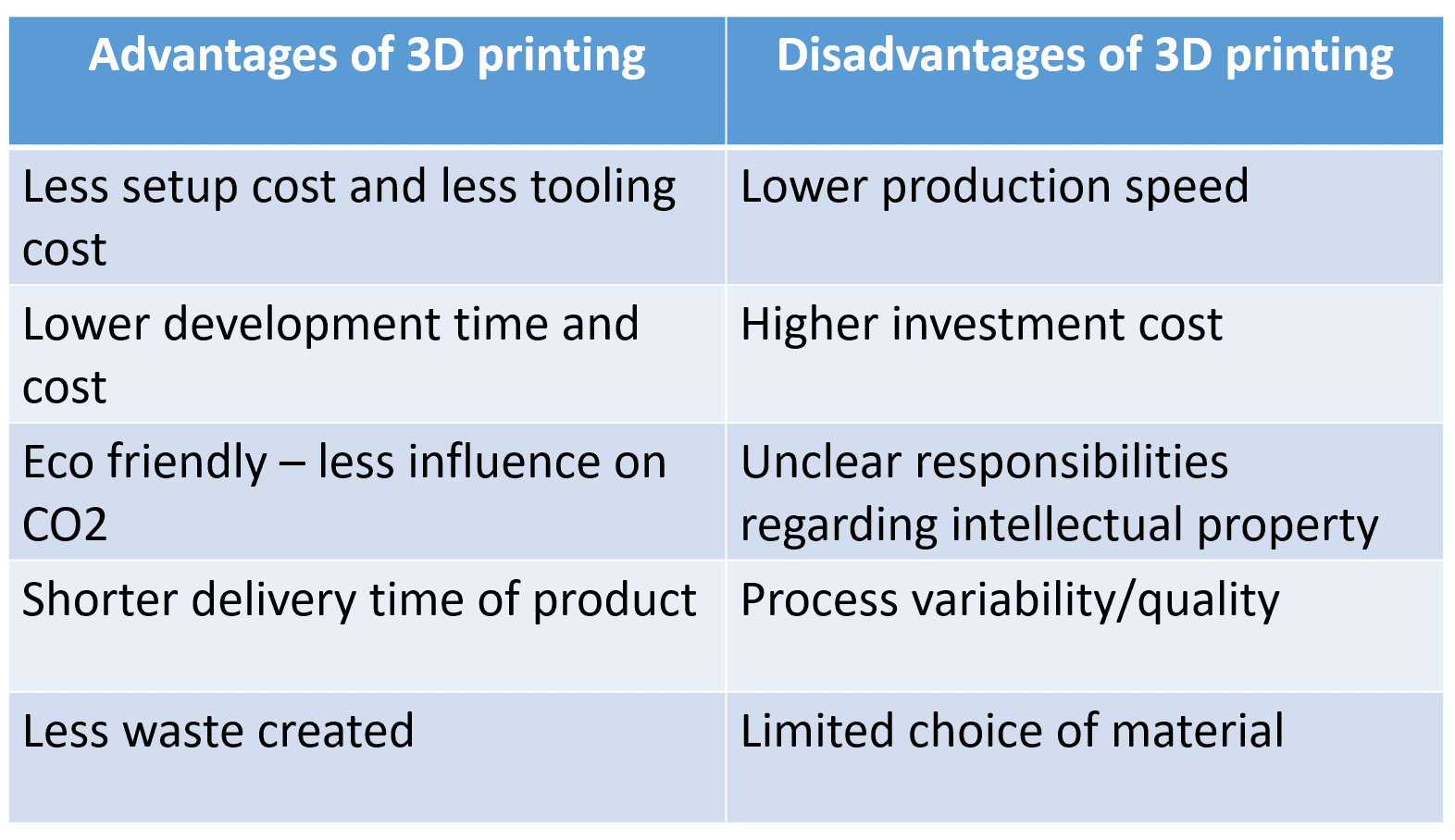
Starting with the 3D Printing, basically, 3D printing is the process of making a physical object from a three-dimensional digital model, typically by laying down many thin layers of a material in succession. In technical language we can say that, 3D printing uses computer aided design to create three-dimensional objects through a layering method. 3D printing is also known as additive manufacturing. A 3D printer is a type of material design printer that designs and builds 3D models and products of devices and components using an additive manufacturing process. 3D printers eliminate the need for further machining or subtracting processes such as cutting and grinding, the final product is built in three dimensions without waste.
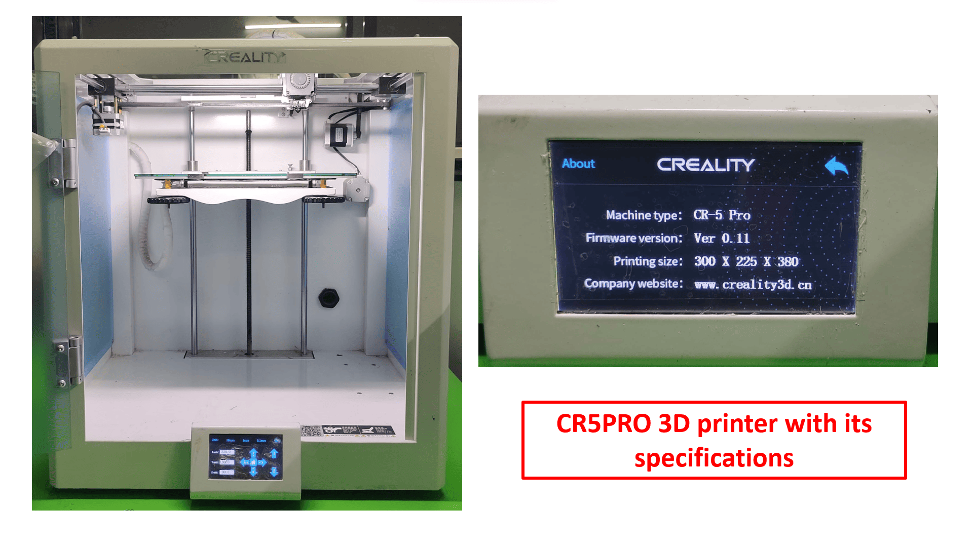
Sanjivani Fab Lab owns Creality-CR5PRO 3D Printing Machine. Here is the picture of 3D printer with its specifications.
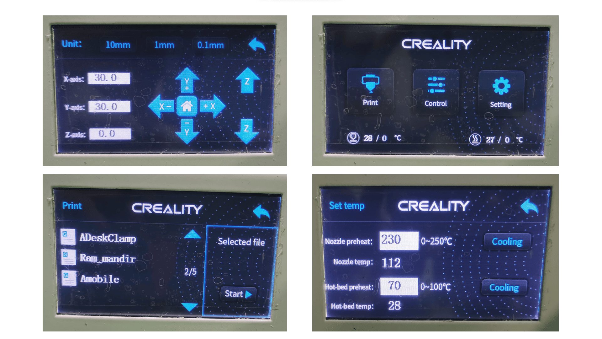
Let's start with the one by one section of 3D printer. So, first one is "Control Monitor/Display", it is basically used to control the whole 3D printer such as to set bed as well as nozzle temperature according to the material used, to move the bed in X, Y and Z plane direction as per your need, to import design files into printer and to start or to stop or to pause the printing process.
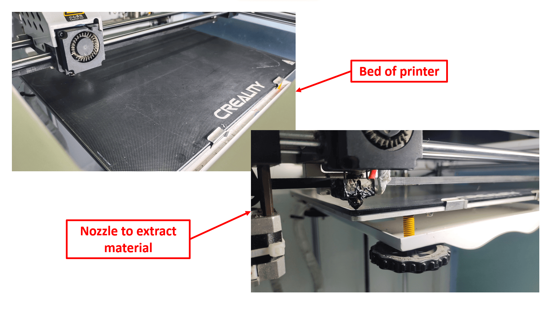
Here is the Bed and the Nozzle of the printer. Bed is being heated upto the required temperature, design is being created onto the bed. And the nozzle is specially used to extract material, is being heated upto required temperature for melting to print an object onto bed.
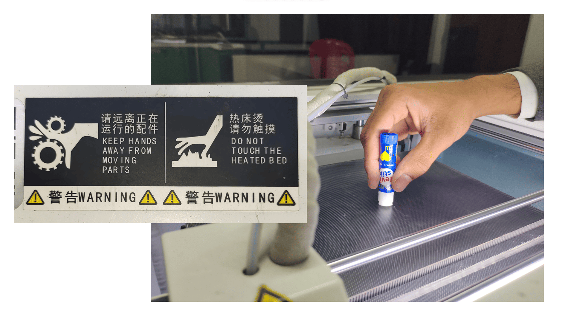
Here are some precautions while using 3D printer-
1) Wear safety glasses and gloves when using your 3D printer.
2) Ensure good ventilation by opening windows or using an exhaust fan.
3) Avoid touching the printer or filament while operating, as they get very hot.
4) Paste adhesive material before start printing on bed which will help to remove workpiece after completion.

Here is the glimpse of orientation of our 3d printer given by my local instructor Mr. Kiran Sir.
3D printer basically work by exposing a layer of photosensitive liquid resin to a UV-laser beam. The resin then hardens in the desired pattern and the object is built layer by layer until it is complete. The quality of the object depends on the printer type.
Group Assignment
The main task in the group assignment is to test the design rule for our inhouse 3D printer. In this assignment we have done characterization of 3D printer. The more details about group assignment you can see here.
Individual Assignment
In this assignment, I have designed a artistic flower pot using SolidWorks Software by refering Sequence Vase Design-YouTube Tutorial. Here is the brief documentation-
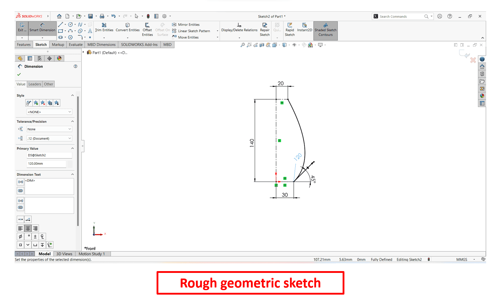
Here, I have drawn a rough geometry of a flower pot using "Line", "CenterLine" and "Spline" commands on Front Plane by assigning exact dimensions as per my requirement.
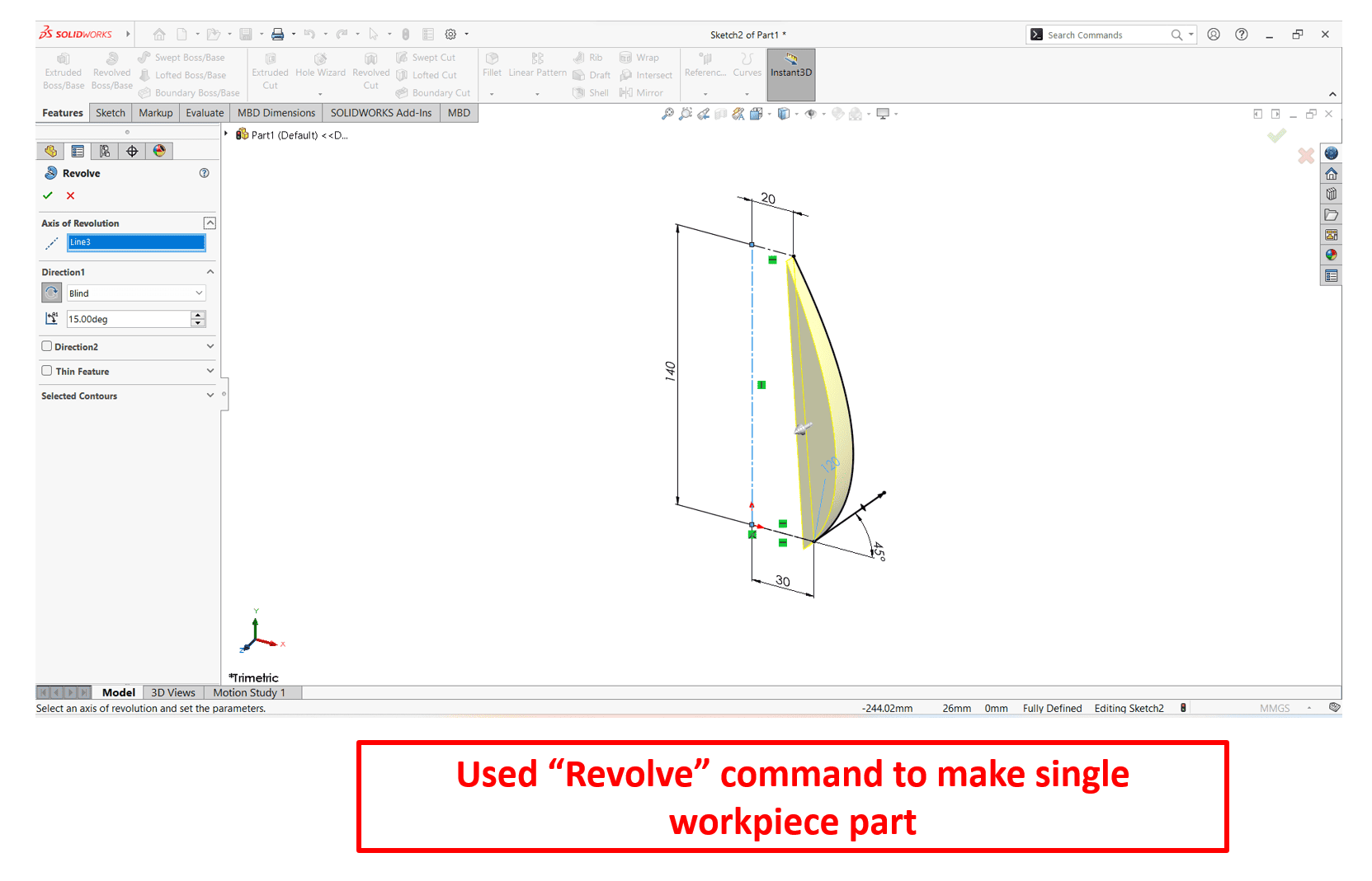
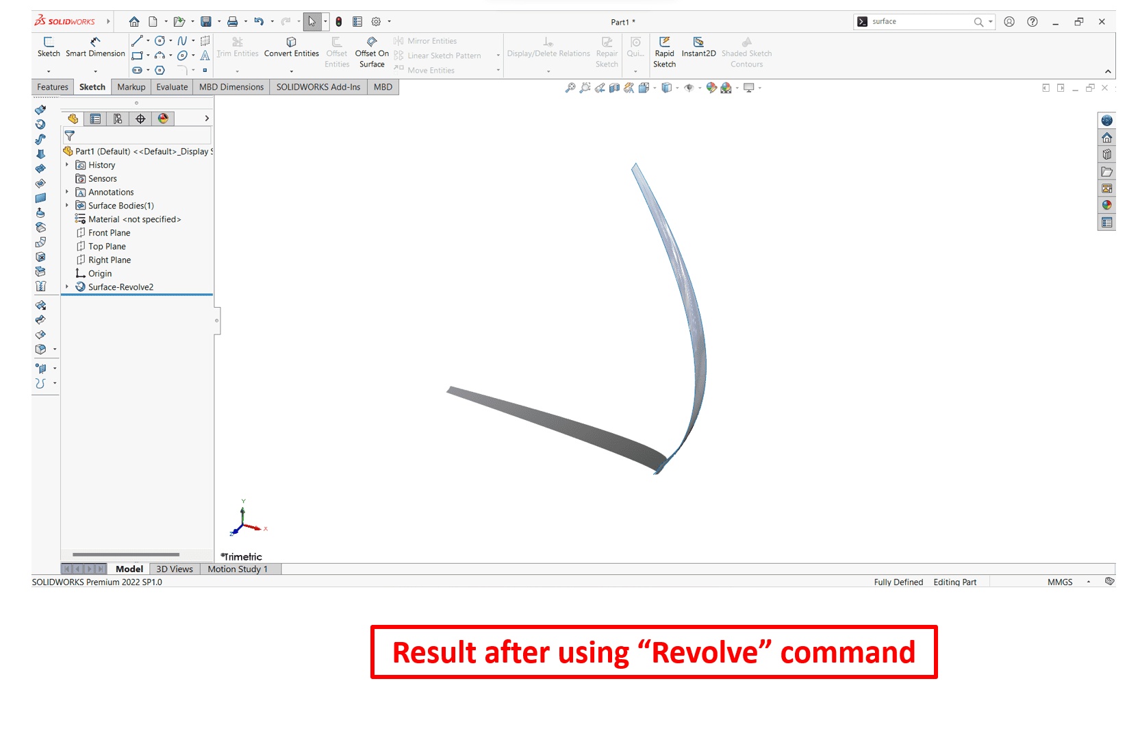
"Revolve" command to create a sketch that contains one or more profiles and a centerline, line or edge to use as the axis around which the feature revolves.

Click Tools > Sketch Entities > Style Spline. In the insert style spline property manager, select from option B-Spline Degree 7. B-splines can be used for curve-fitting and numerical differentiation of experimental data. In CAD, spline functions are constructed as linear combinations of B-splines with set of control points.
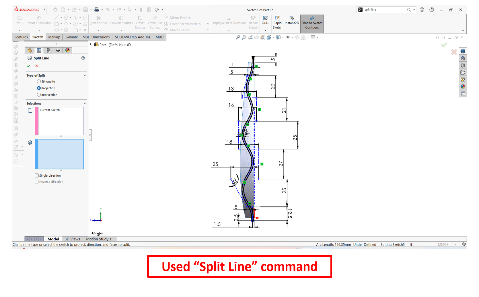
"Split line" command is used to divide a selected face into multiple separate faces.
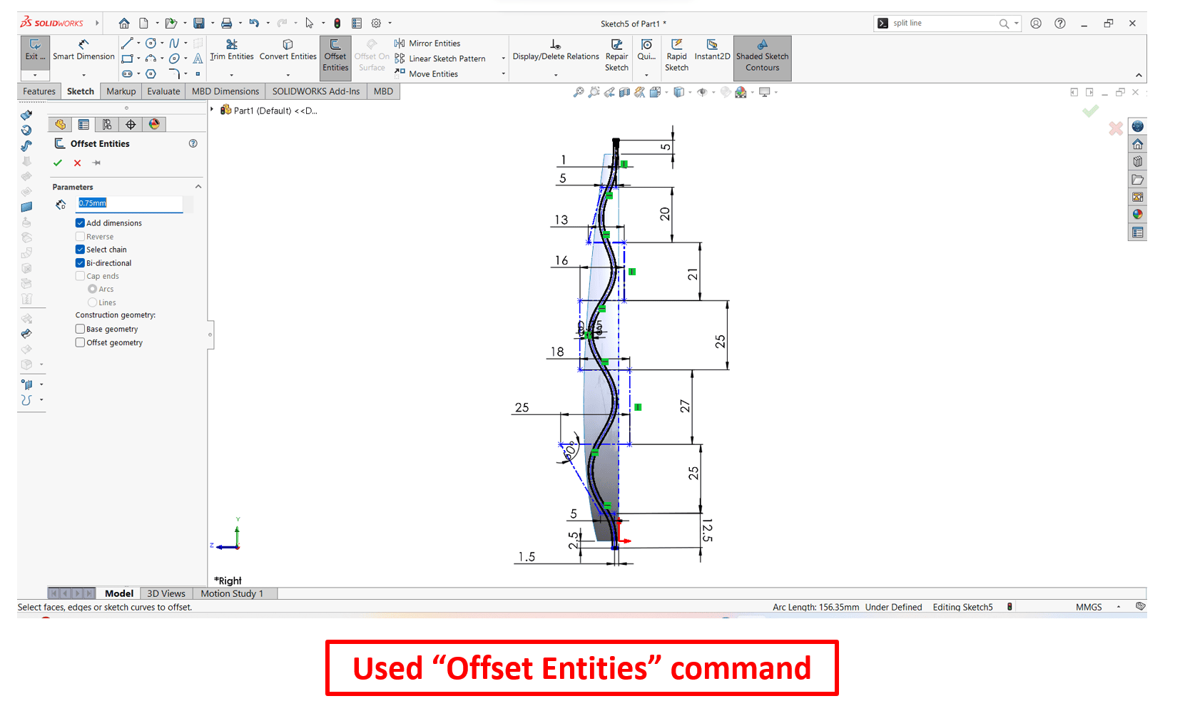
"Offset entities" command is used to create a copy of existing sketch entities at a specified distance from the original entities.

In SolidWorks "Mirror Entities" command allows to create a mirrored copy of selected sketch entities along a plane.
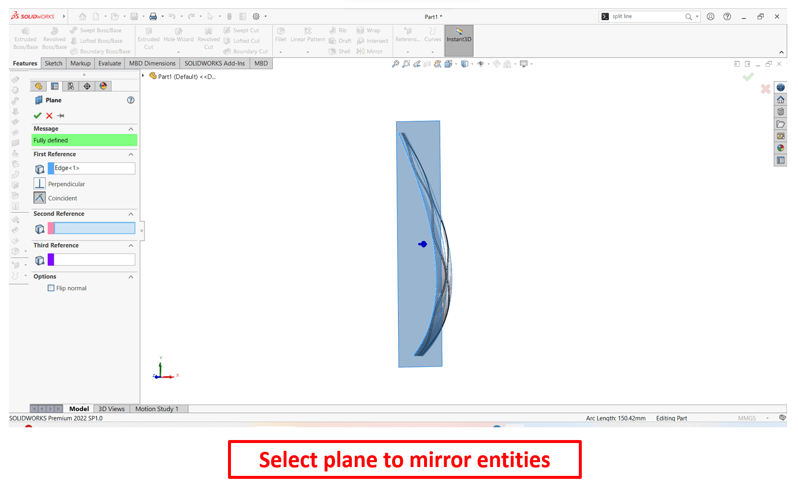
Here, I have selected a plane which I have to mirror entities.
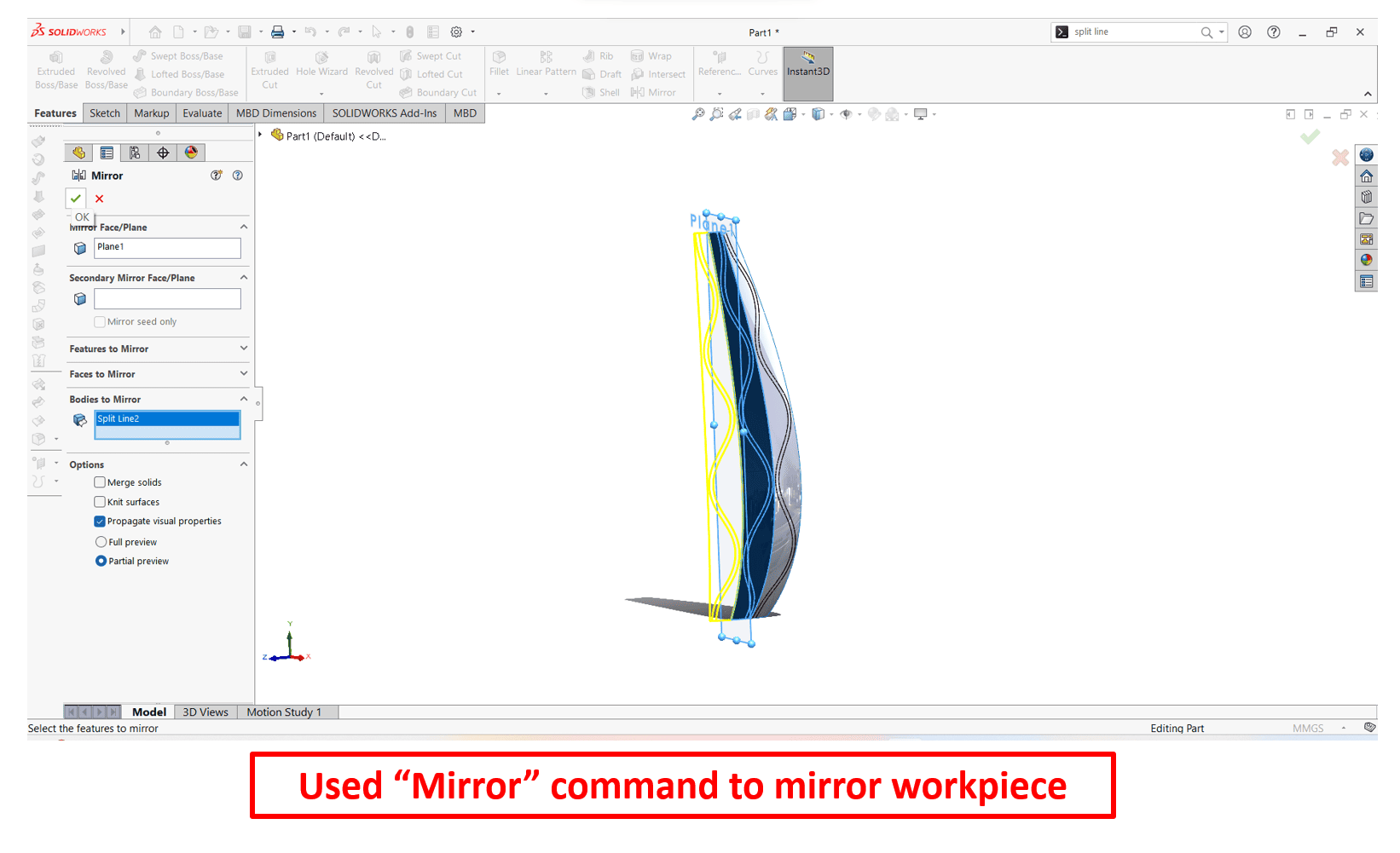
Again, I used "Mirror Entities" command.

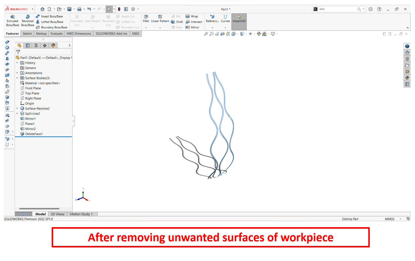
To remove or delete unwanted face or surface, I have used "Delete Surface" command.
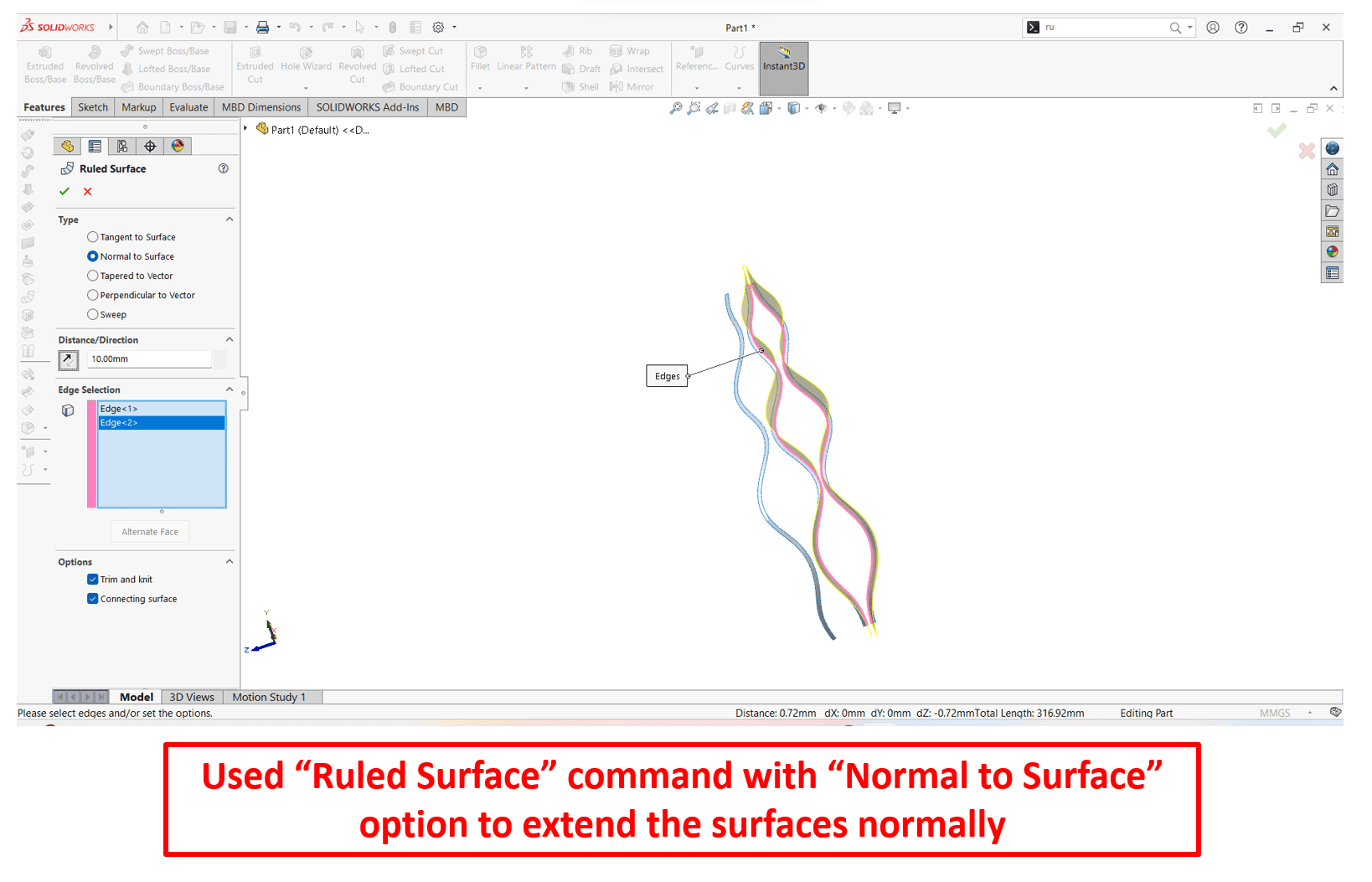

This process allows to generate a rules surface with the normal direction controlled by the "Normal to Surface" option. Ruled surface is a type of surface in geometry that is defined by straight lines connecting points in space.

"Isolate" option is a tool that allows to focus on a specific component or feature in a more clutter-free environment(workspace that is free from unnecessary visual elements). This is particularly helpful when working with complex assemblies.
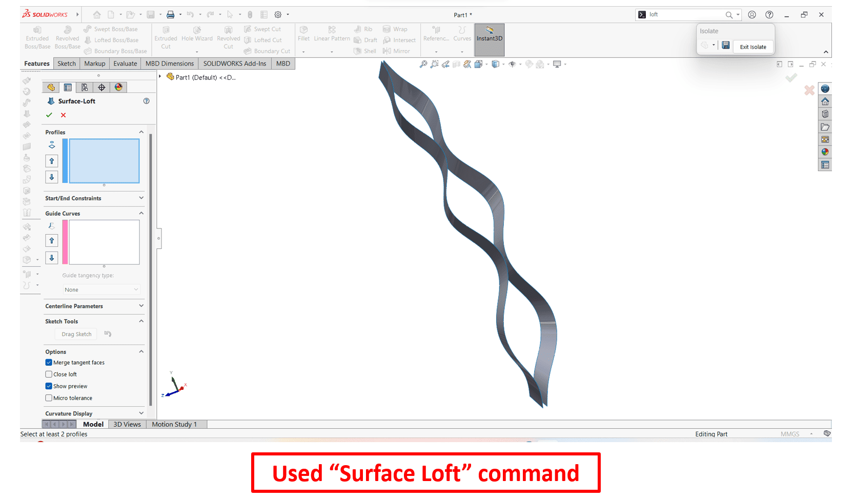
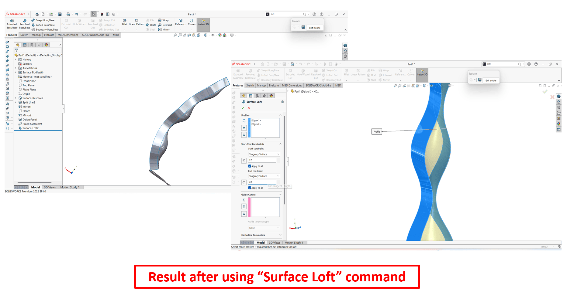
"Surface-Loft" allows to create a surface by blending or transitioning between multiple profiles. This is particularly useful when there is a need to create complex shapes or smooth transitions betweek different sections.
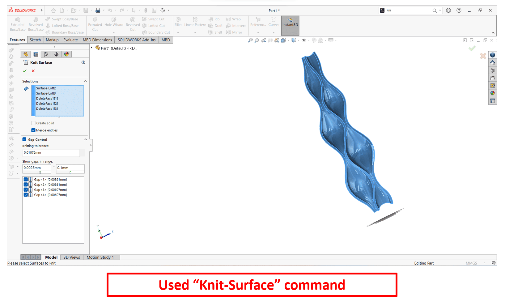
"Knit-surface" feature allows to combine or merge multiple surfaces into a single, connected surface. This is useful when there is need to created separate surface bodies and want to unify them into a single surface.
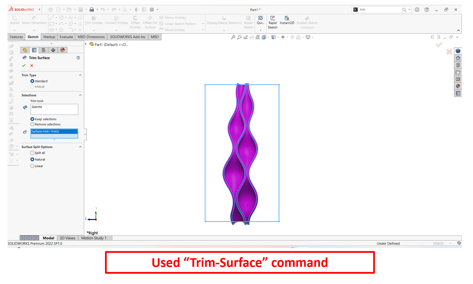
To cut or trim surfaces using one or more sketch curves or surface curves, "Trim Surface" feature is used.

The "Boss-Extrude" feature is a tool that allows to add material to a part by extruding a sketch in specified direction. This is a fundamental feature used to create three-dimensional geometry.
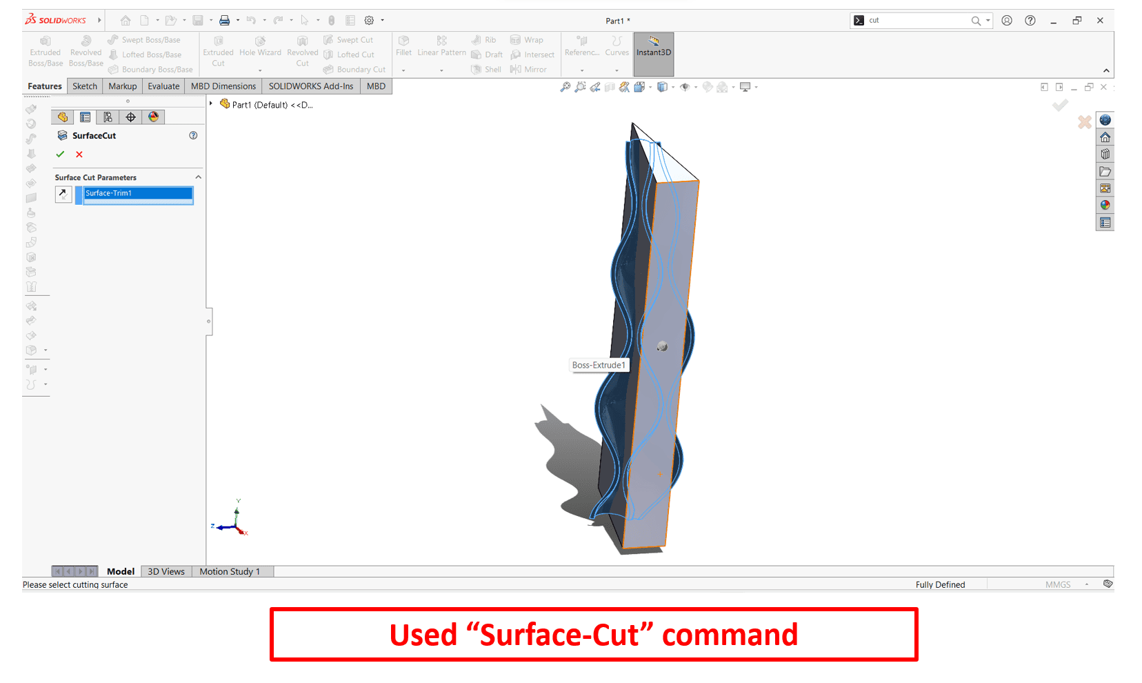
"Surface Cut" feature allows to cut away or trim using one or more sketches or surfaces curves. This is useful when you need to modify the shape of a surface by removing or trimming specific areas.
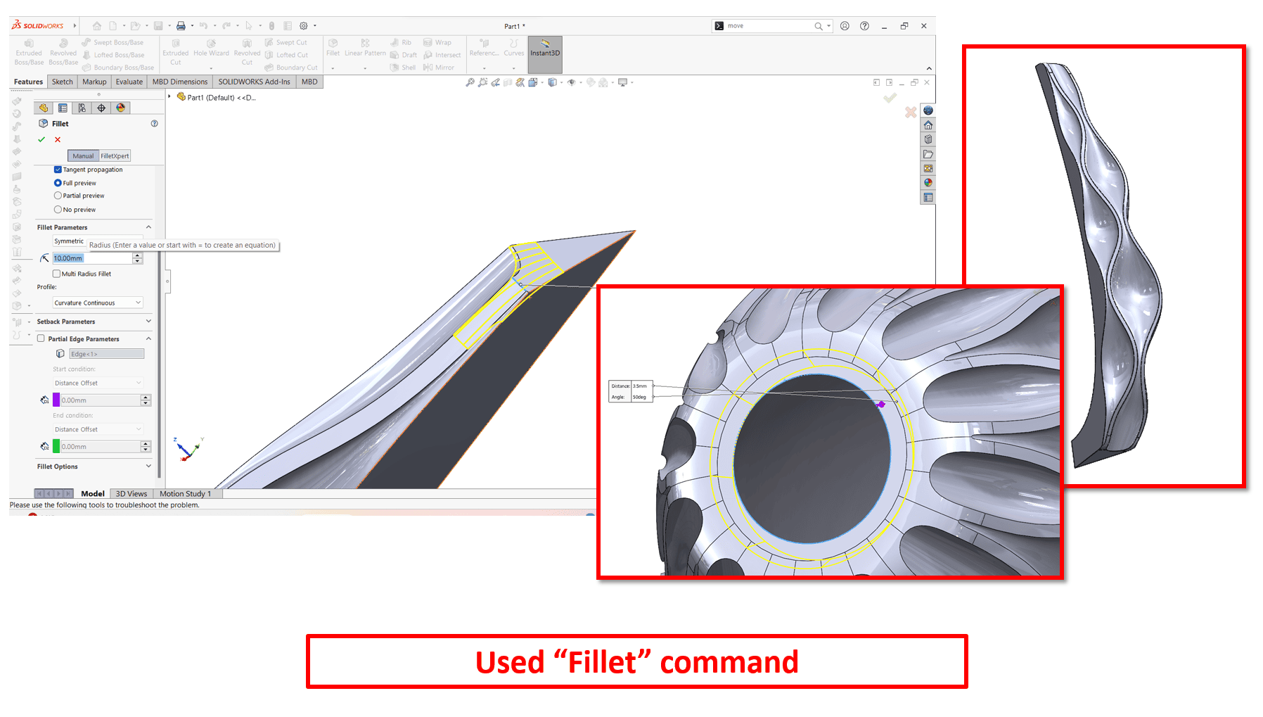
The "Fillet" feature is used to create rounded corners or edges on a 3D model. Fillets help smooth transitions between faces or features, improving the aesthetics and potentially stress concentrations.
At the end, I have changed the material of flower pot to "Gold" and saved it as a "flowerpot.stl" file. Here is the final view of my flower pot design.
DAY-03
Now, moving towards the 3d priting of designed flower pot.
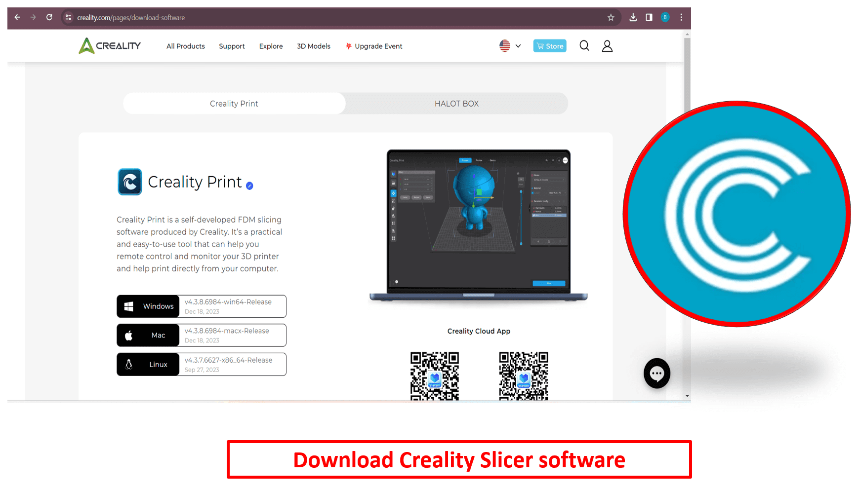
Before priting the object, I have converted my ".stl" to ".gcd" file. To convert STL file into GCode file, I used Creality Slicer Software which is suitable for our 3D printer. So, to download Creality Slicer Software by clicking on "click here to download."
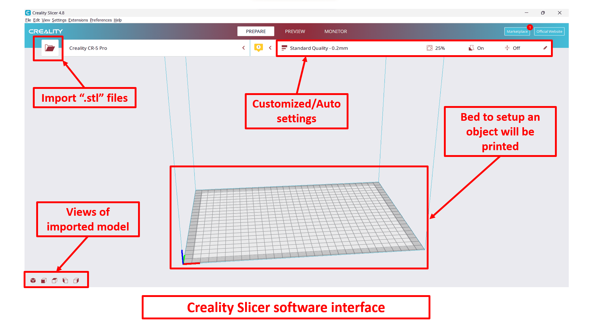
Here is the interface of the Creality Slicer Software which includes import button to import STL file for GCode conversions, customized or automated settings such as bed and nozzle temperature, infill settings, quality maintenance, support generation or removal, etc. It also includes views of imported models such as 3D, front, top, left and right view. Bed is used to place an object will be printing.

Now, I have imported my "flowerpot.stl" file into Creality Slicer software using import button to convert into GCode file.
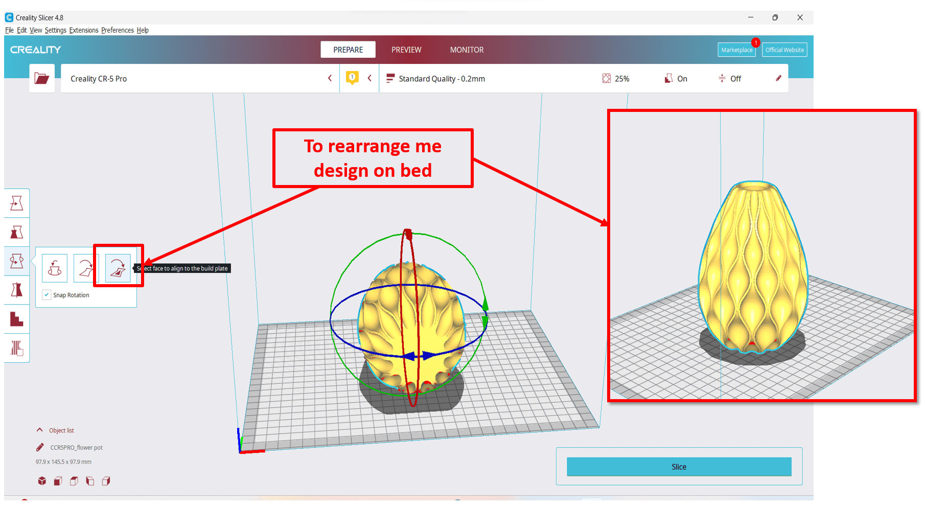
Here, I have rearranged my imported file in proper direction by using "rotate" option.
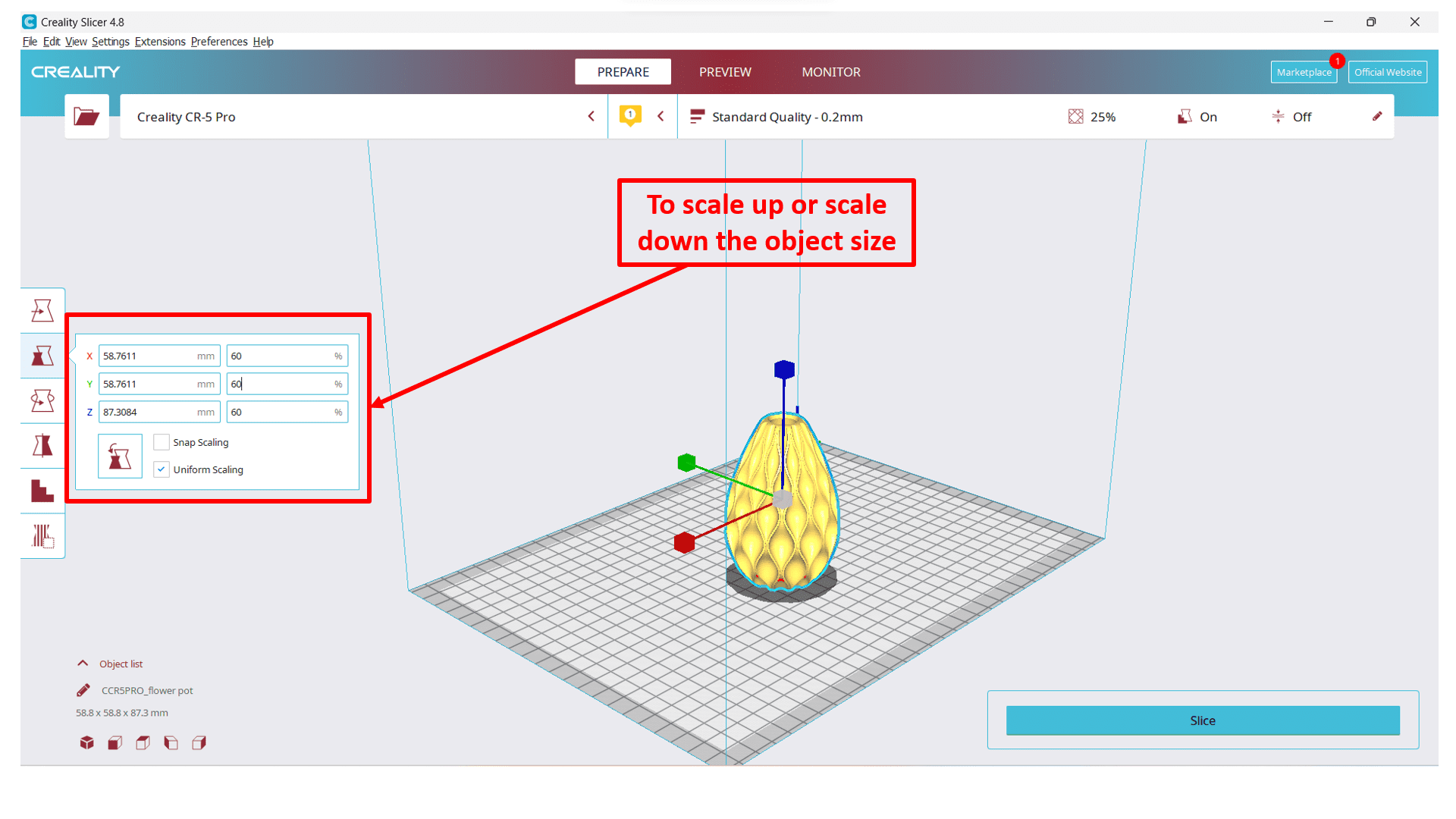
Now, I wanted to change aspect ratio of my object, I thought it was too big. So, I have scaled down it by using "Scale" option. I have scaled down it from 100% to 60%.
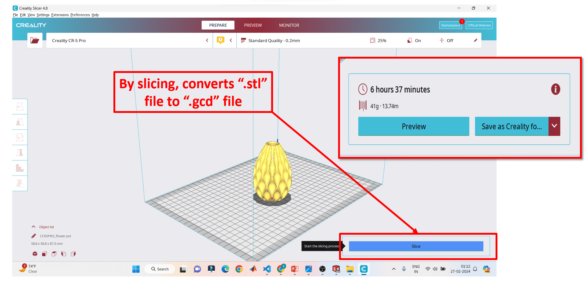
By clicking on "Slice" button, I got my converted GCode file which I wanted to import into 3D printer for printing. Along with GCode file, I got the time taken by the object to be printed.
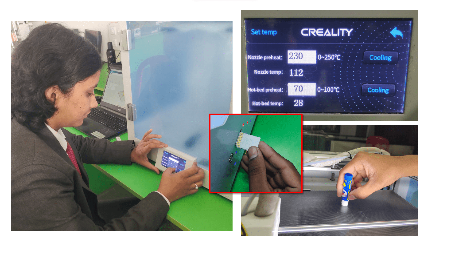
Before started printing, I have adjusted the Bed and Nozzle temperature in software as well as in 3D printer. Here, I have used PLA material. So, I have set bed temperature as 70 deg.cel. and nozzle temperature as 230 deg.cel. I uploaded GCode file into the printer by inserting a chip where I have saved my GCode file. Also, I pasted adhesive glue on bed for better output.
Here is the short clip of my Sequence Vase-Flower pot which 3D printing process. You can see that, nozzle placed material on bed layer by layer as per instructions given by GCode.
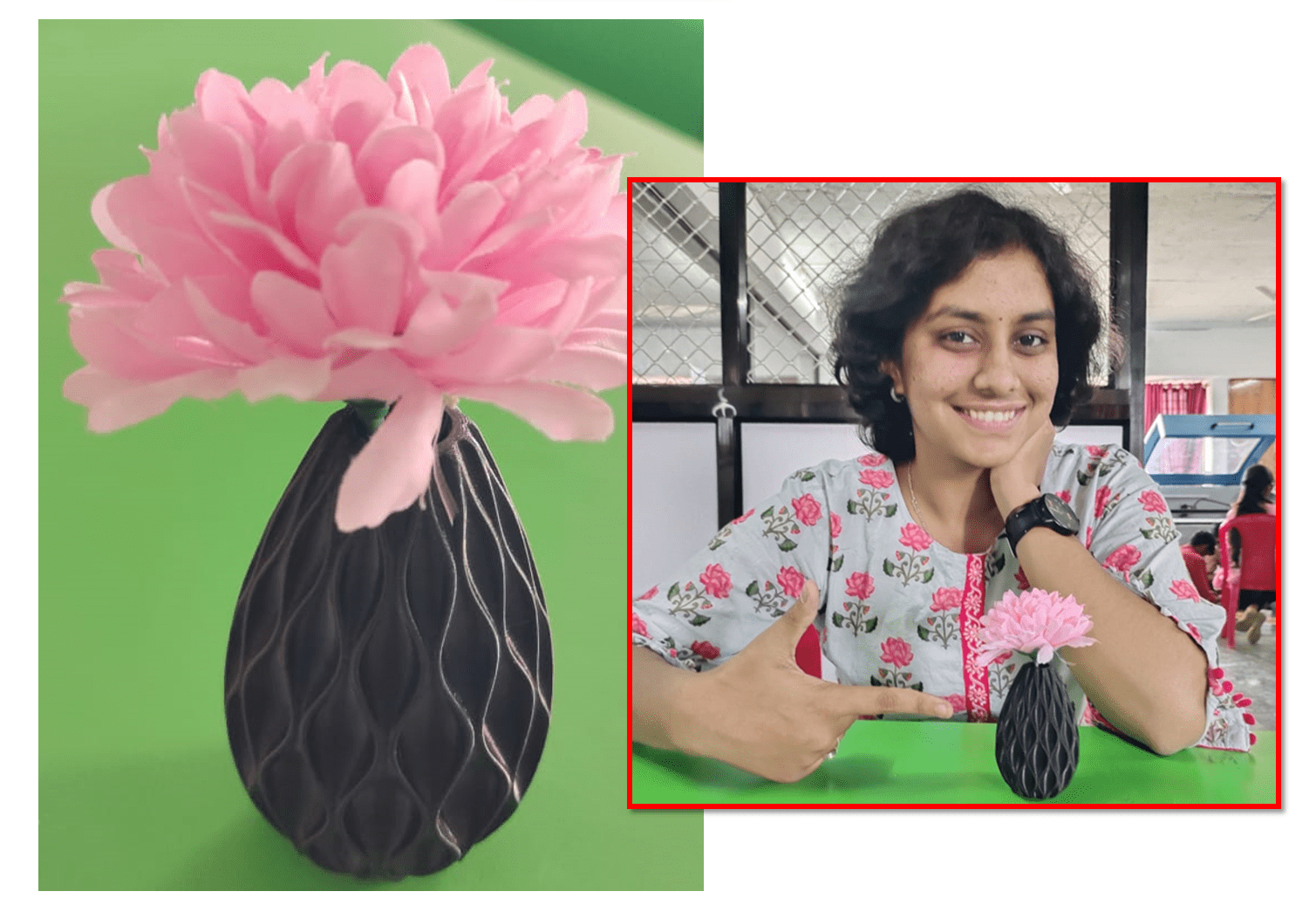
Here is the final output object after the printing. I really like the finishing of the object!
DAY-04
Now, moving towards the 3D Scanning assignment of this week.
What is 3D Scanning of an object? 3D scanning is the process of analyzing a real-world object or environment to collect three dimensional data of its shape and possibly its appearance. The collected data can be used to construct digital 3D models. 3D scanning makes it possible to check the entire shape of the manufactured product with the original CAD design and find deviations instantly by displaying the data in a 3D whole deviation color map. In short, 3D scanning is a way to capture a physical object's exact size and shape into the computer world as a digital 3-dimensional representation.
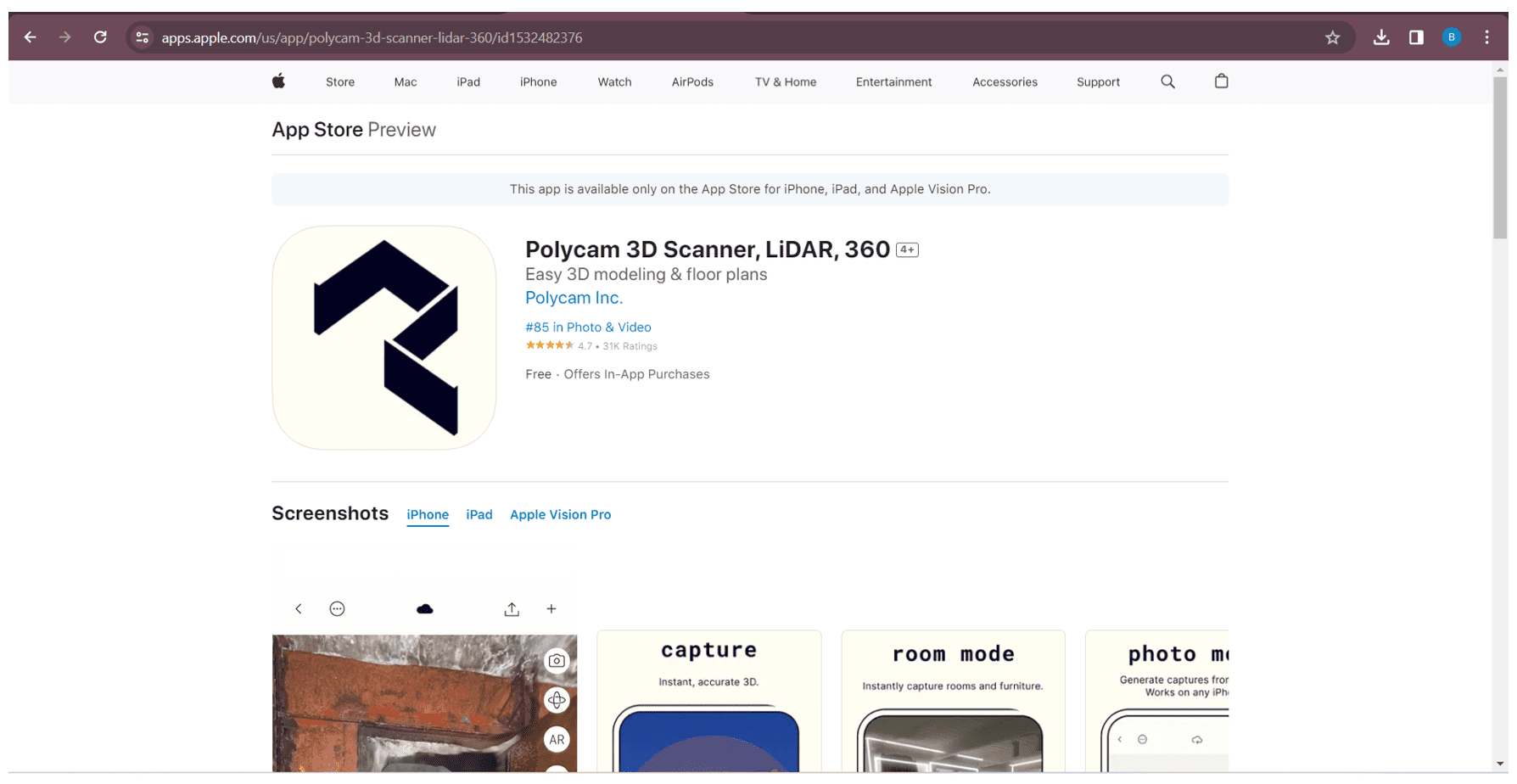
I wanted to scan myself and print my own statue but I don't have any idea about it. I shared my idea with one of my senior, he suggested me to use Polycam 3D Scanner App for scanning. He has already used this app in his iPAD, tought me how to use it and generate ".stl" file after scanning any object.
Polycam is a 3D scanning app available for iPad. It allows users to capture 3D scans of objects of objects or environment using the iPad's camera. The app utilizes the device's LiDAR sensor for more accurate depth sensing, resulting in detailed 3D models. So, click here to download the Polycam software.
Here is the videography while scanning myself using Polycam 3D scanner in iPad.

After I have scanned myself, here I got the ".stl" file of my miniature statue. Here, you can see that there are many impurities in the workpiece. To remove this impurities and to improve the finishing of the object, I downloaded MeshMixer Software through the following link- Click here to download.

This is the interface of MeshMixer software. I imported ".stl" file into the software to remove impurities.
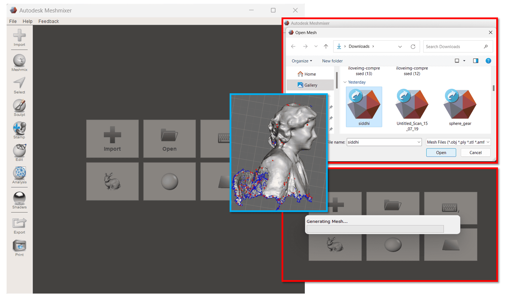
Here I have uploaded my existing impure ".stl" file into the software by clicking on "Import" option.

I have "Selected + delete" option to delete unwanted surface or unwanted curves of the object. And used "Make a Solid" option to make impure file into solid with pure form.

Now, I exported my newly edited file again into ".stl" form for printing purpose.
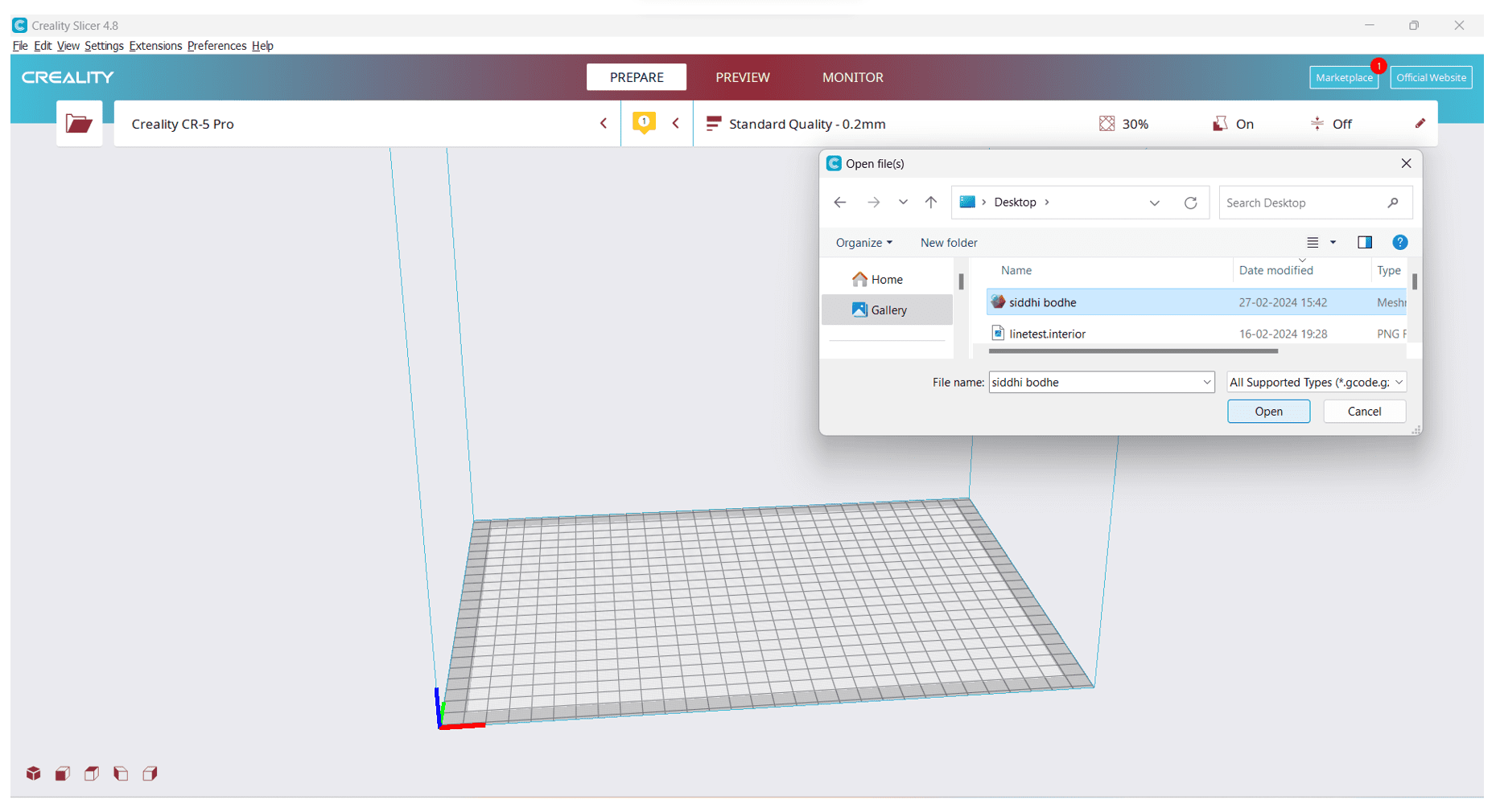
Again, I have imported newly edited ".stl" file into Creality Slicer software to convert into GCode format for printing purpose.
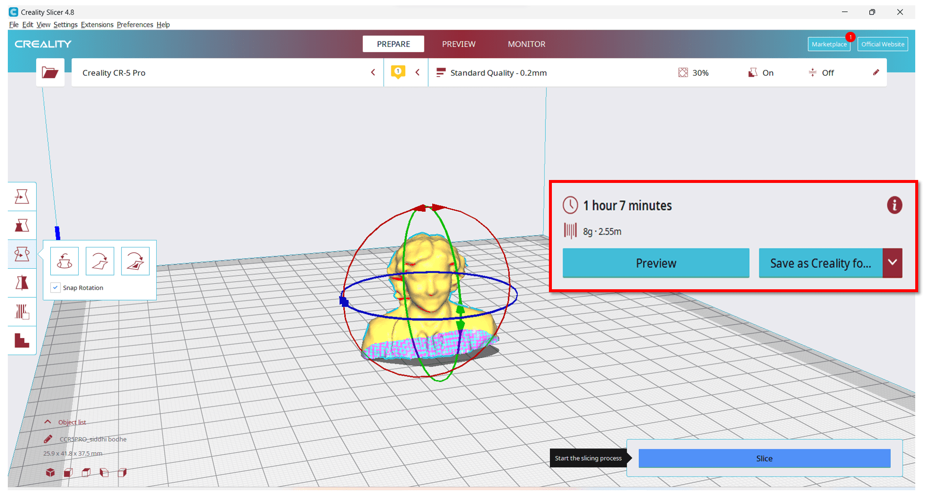
By clicking on "Slice" button, I got my converted GCode file which I wanted to import into 3D printer for printing. Along with GCode file, I got the time taken by the object to be printed.
Here is the final output after printing.
