On the Wednesday of second week, Mr. Neil sir conducted our second global session. He took the random generator in first 90 minutes. He gave us overall explaination about week-02 which includes Raster and Vector images, FreeCAD 3D CAD Software, Image and Video size compression softwares and some online CAD model websites. He motivated us to explore in 2D and 3D designing world.
DAY-02
On the next day, instructor Mr. Suhas sir conducted our online meet to explain what we are going to do in this week. He gave reference to explore 3D softwares like SolidWorks, Fusion 360, FreeCAD,etc. And also my instructor Mr. Kiran sir taught me how to use OBS Video Editor software. By referring both of them I started exploring softwares. I have used GIMP for Raster drawing, INKSCAPE for Vector drawing and Solidworks, Fusion 360, AutoCAD for 2D as well as 3D designs are as follows.
First of all we have to know about 2D drawings. Basically, 2D means 2 dimensional, draw along two axes or planes. It can be X-axis, Y-axis and Z-axis. It is the composition includes the dimensions of length and width but does not include depth. There are two types of 2D images- Raster and Vector.
1. Raster Image
What is known as Raster Image? Basically, Raster image consists of rectangular arrays which are placed uniformely with sampled values. Each rectangle known as a pixel or picture element.Each pixel has one or more numbers associated with it and has specified colour according to pixel should be displayed. It is the simplest representation of an image having specified pixel by three 8 bit (24 bits total) color values including defined amount of red, green and blue color respectively in each pixel. Raster image can be in JPEG, PNG, GIF, PPM,etc. format.
To learn about the raster image I have explored "GIMP" software.
GIMP
GIMP is the GNU Image Manupulation Program which is used for image manupulation and image editing. GNU is a free operating system and GIMP follows all the GNU standards.
It is a free and open source raster graphics editor. In this software firstly I learnt to draw "Mandala" art. Basically, "Mandala" is a sanskrit word refered as a "circle" and traditionally Mandala is a geaometric design or a pattern that symbolized the universe in its ideal form. Specially, it's purpose is to express joy or happiness.
So, following are the steps to draw Mnadala art in GIMP.
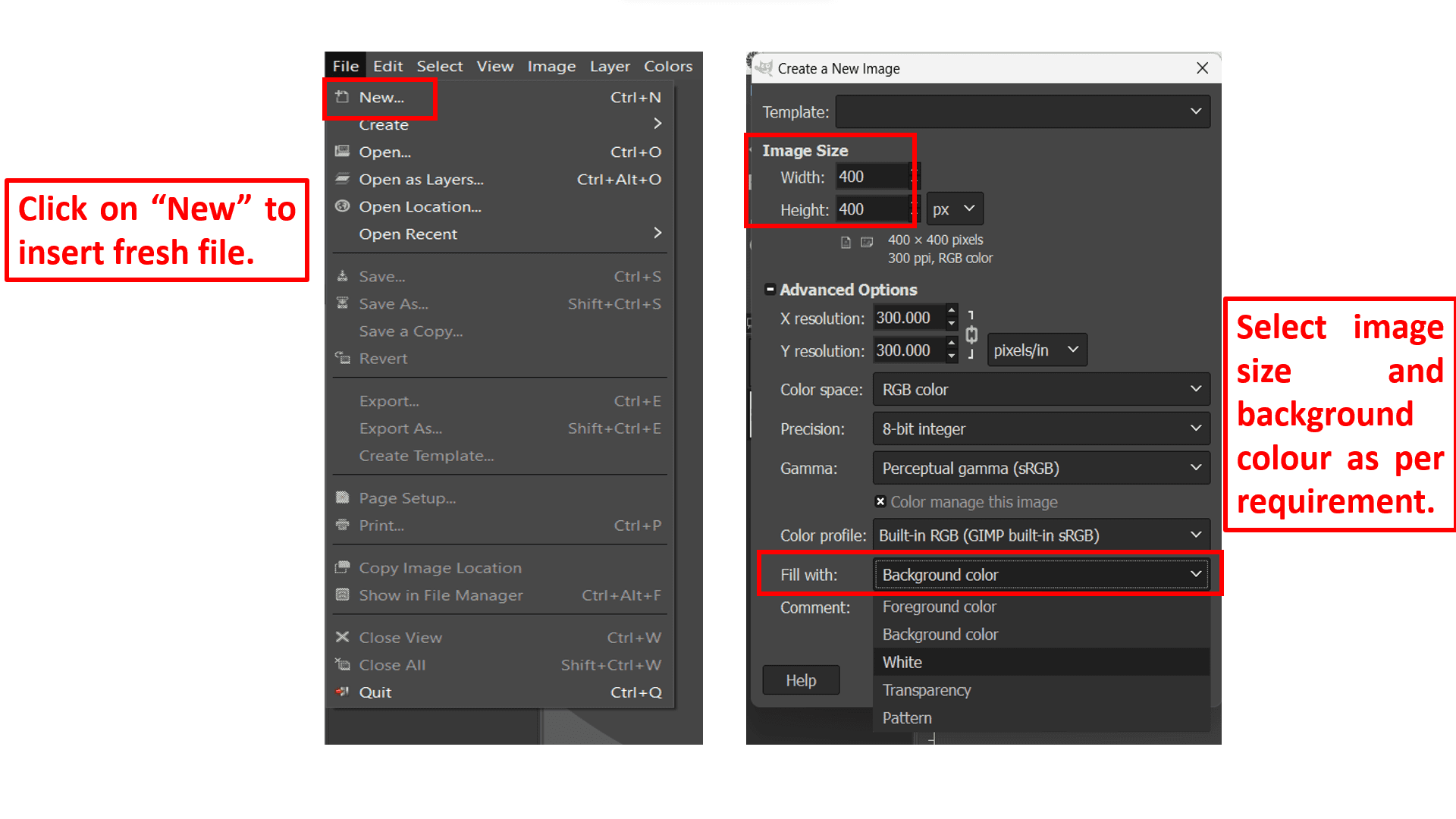
Firstly, I opened the GIMP and click on "New" from "File" tab to insert fresh blank document so that I can start to design my drawings. After clicking on "New" option they are asking to enter page layout including height and width. So, enter required dimensions as per your need. I have entered 400px by 400px. Also, I selected "White" as a background.
Now, go to "Windows" tab and click on "Symmetric Painting" option from "Dockable Dialogs" option to draw a symmetric pattern along drawing axis. Then, select "Mandala" option from "symmetry" tab which is located at the right side of GIMP interface. Enter the number of points used to draw Mandala art. Here I have entered 15 points. Then, by clicking on "Brushes" tab you can select pattern from given list of pattern.
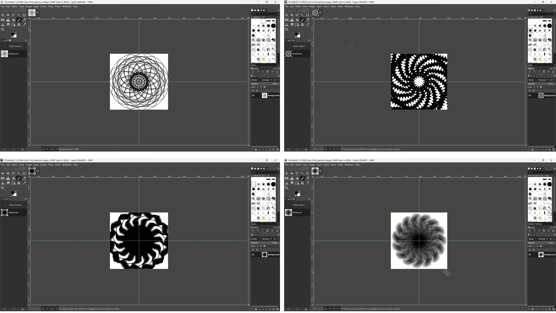
Here, I have used basic line, dot, star and dotted pattern design to develop my Mandala art.
Here is the video of Mandala art where I have used different design patterns to createmy art.
2. Vector Image
Vector Image can be created using mathematical formulas to represent the image, rather than using a grid of pixels. This type o image is often used for logos because it can be scaled upto any size without losing the original quality of image. Vector image can be in SVG, AI, EPS, PDF, CDR, etc. format.
To learn about the vector image I have explored "CorelDRAW" software.
CorelDraw
CorelDRAW is developed by Alludo, used to edit vector graphics and designs. Vector graphics are created in bunch of packages and each package has an object. Each object can be edited seperately in terms of shape, size, colour, etc. without losing its original quality.
Here, I have inserted my image to divide into different packages to engrave my portrait photo on cardboard. So, following are the steps to engrave self portrait in CorelDRAW.
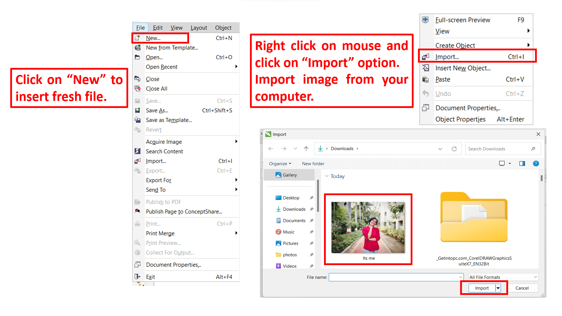
Firstly, I opened the CorelDRAW and click "New" from "File" tab to insert fresh blank document. After inserting a new blank document "Right click" on mouse to import the image. Import image by clicking on "Import" option. Now, select or drag image in the new blank document.
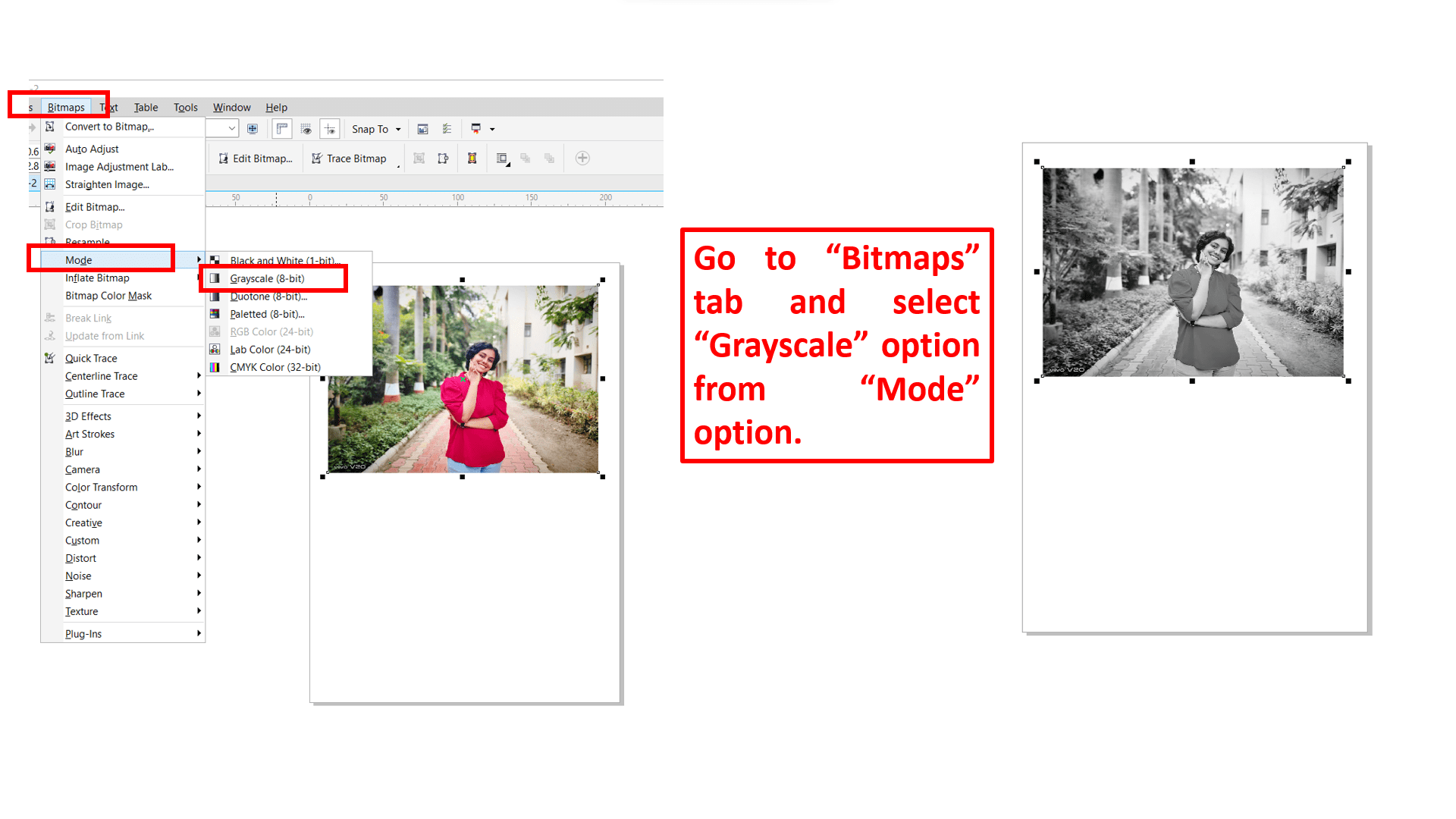
Now, go to "Bitmaps" tab and select "Grayscale" option from "Mode" option which causes to change in colour of imported image.
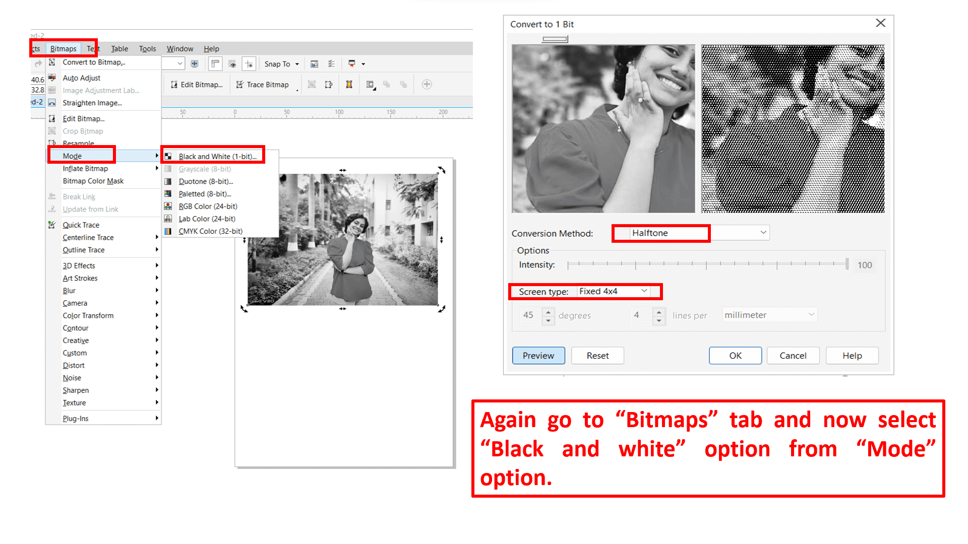
Again go to "Bitmaps" tab and now select "Black and white" from "Mode" option. then there is a popup window occurs, asking to select conversion methos and screen type. So, here I have selected "Halftone" as "Conversion Method" and "Fixed 4*4" as "Screen type" which leads to convert a simple image into numbers of packages consist of object each.
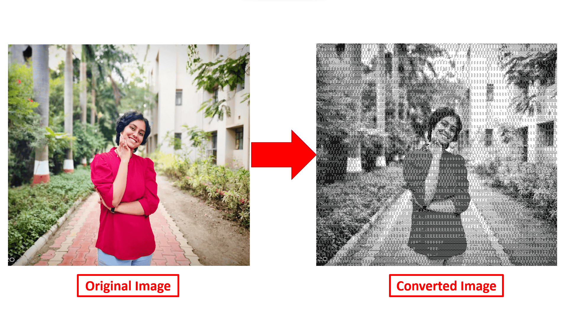
So, here is the converted image as a final output.
Raster Image Vs Vector Image
Vector images are basically created using lines and shapes that are mathematically defined. This means that this image can be maximized or minimized upto ny range without losing its original quality. On the other hand, Raster Image are created using pixels, consists of colours with defined values. This type of images loses its original quality on miximizing but it can be minimized without any problem.
DAY-03
On the third day, I have started to explore 3D design softwares. What is meant by 3D drawings? So, 3D means 3 dimensional includes 3 axes or planes. This drawing includes dimensions of height, width and depth. Basically, it is used to visualize any hypothetical object in physical form.
1. SolidWorks
SolidWorks is a 2D and 3D CAD software developed by Dassault Systems specially used for product development solution.
Here, i have did the assembly of Knuckle joint. Knuckle joint is mechanical joint that connects two rods or pipes at an angle, allowing limited angular movement and rotation between them. It is typically used in bicycle chain links, suspension systems and steering linkages in vehicles.
Knuckle joint assembly consists of:-
1) Two rods are to be connected.
2) Fork End.
3) Eye End.
4) Knuckle pin.
5) Collar.
6) Tapper pin.
Here are the brief description and design of each part. 1) Two rods:-
The knuckle joint is connected with two shafts. One rod has an eye at one end whereas the other has two ends that resembles a fork.Now to draw 3D drawing of all the parts I have used some basic command of SolidWorks like sketch, trim, dimensions, normal to, units,etc.
2) Fork End:-
Fork end typically has two ends and fork like structure. Because one end is for entering the knuckle pin and the other for the collar where tapper pin is place. This joint is completely closed.To draw this part I have used following commands:-
(a) Firstly I selected "Top plane" to draw this part.
(b) I have inserted Centerline using "centreline" command as a reference to draw geometry of a part.
(c) I have added Rectangle using "Corner point Rectangle" command to make body of this part.
(d) Then using "Boss-Extrude" command to make solid body of drawn geometry.
(e) "Mirror Entities" command is used to draw exact geometry along horizontal or vertical plane.
(f) "Convert Entities" command is used to project edges of a face onto the active sketch.
(g) To convert sharp edges into smooth edges I used "Fillet" command.
(h) I used "Vertical" relation to align two or more Entities like line, circle, mid points, corner points, etc. vertically with each other along vertical plane.
(i) "Cut-Extrude" used to remove unwanted material from solid body and provide proper shape to a part.
(j) Using "Tangent" relation I have aligned circle and line with each other.
(k) "Symmetric" relation is used to make two or more line symmetric with each other along a same plane.
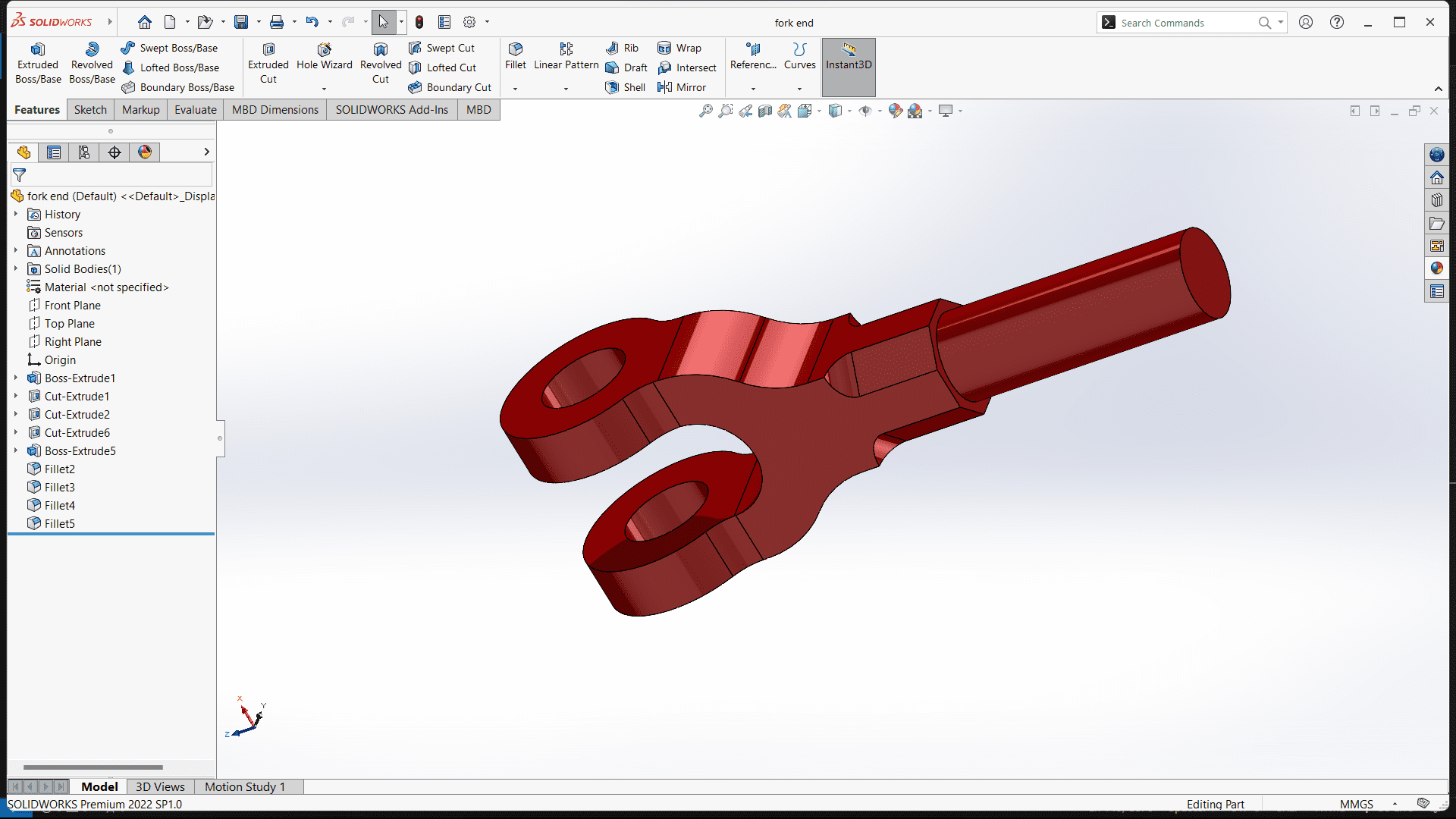
(l) By using all the above mentioned commands I created Fork End part and lastly changed its colour into Orange using "Edit Appearance" command.
Following picture shows the design of Fork End.
3) Eye End:-
The eye end has two holes is positioned between fork end of the two holes so that all holes are joined. After completing drawing of Eye End I learned following commands.
(a) Firstly I selected "Front plane" to draw this part.
(b) I have inserted Centerline using "Centreline" command as a reference to draw geometry of a part.
(c) I have added two circles using "Circle-Radius" command aligned with origin.
(d) "Corner rectangle" command is used to insert rectangle from corner end points.
(e) I used "Symmetric" relation to align circle and rectangle symmetrically.
(f) To convert sharp edges into smooth edges I used "Fillet" command.
(g) Then using "Boss-Extrude" command to make solid body of drawn geometry.
(h) I used "Horizontal" relation to align two or more Entities like line, circle, mid points, corner points, etc. horizontally with each other along horizontal plane.
(i) "Circular sketch pattern" command is used to create duplicate geometry of selected geometry along centre point in circular pattern.
(j) Finally I used "Edit appearance" command to change its colour into Red colour.
Following picture shows the design of eye end.
4) Knuckle Pin:-
The knuckle pin is inserted through holes, firmly joining them. The tapper pin is inserted into small hole of the knuckle joint.To draw this part I have used following commands:-
(a) Firstly I selected "Front plane" to draw this part.
(b) I have used "Line" command to draw geometrical body of a part.
(c) "Revolve Boss/Base" command used to add or remove a material by revolving around one or more profiles around centerline.
(d) I have added circle using "Circle-Radius" command aligned with origin.
(e) I used "Horizontal" relation to align two or more Entities like line, circle, mid points, corner points, etc. horizontally with each other along horizontal plane.
(f) "Cut-Extrude" used to remove unwanted material from solid body and provide proper shape to a part.
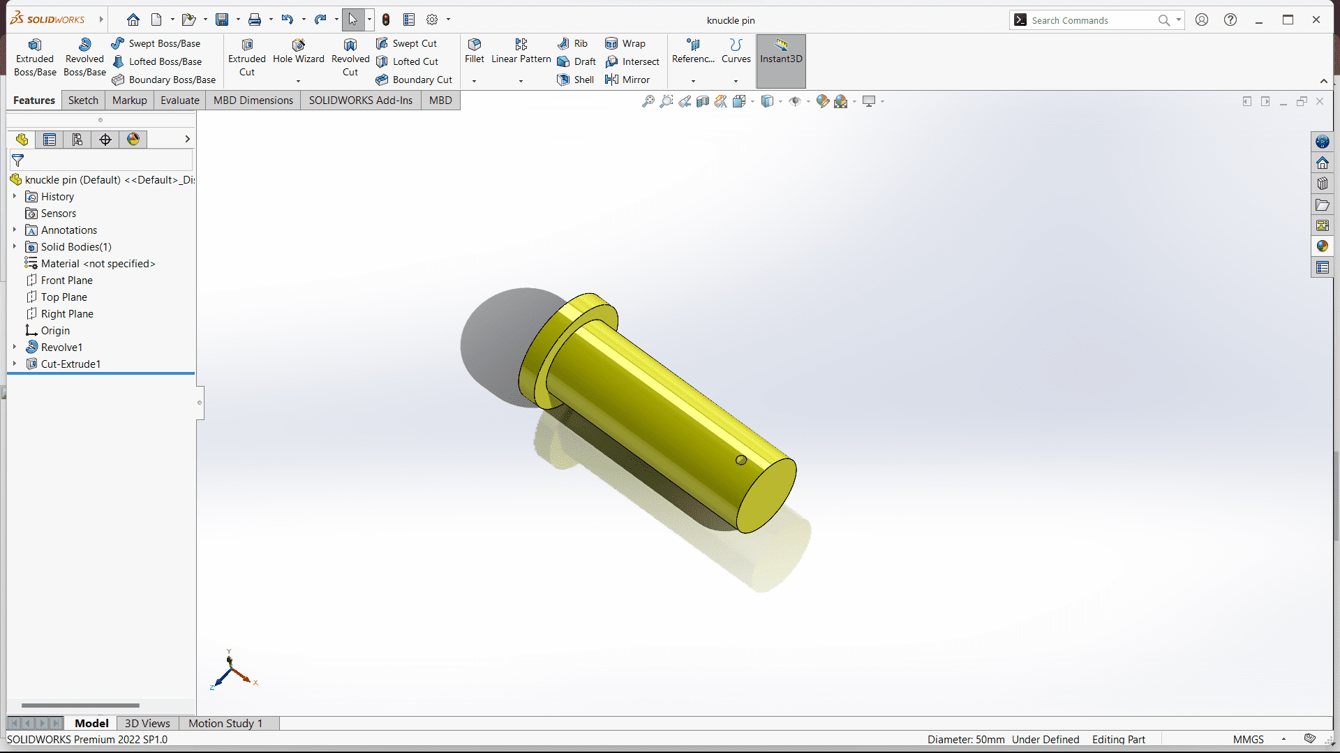
(g) Finally I used "Edit appearance" command to change its colour into Yellow colour.
Following picture shows the design of knuckle pin.
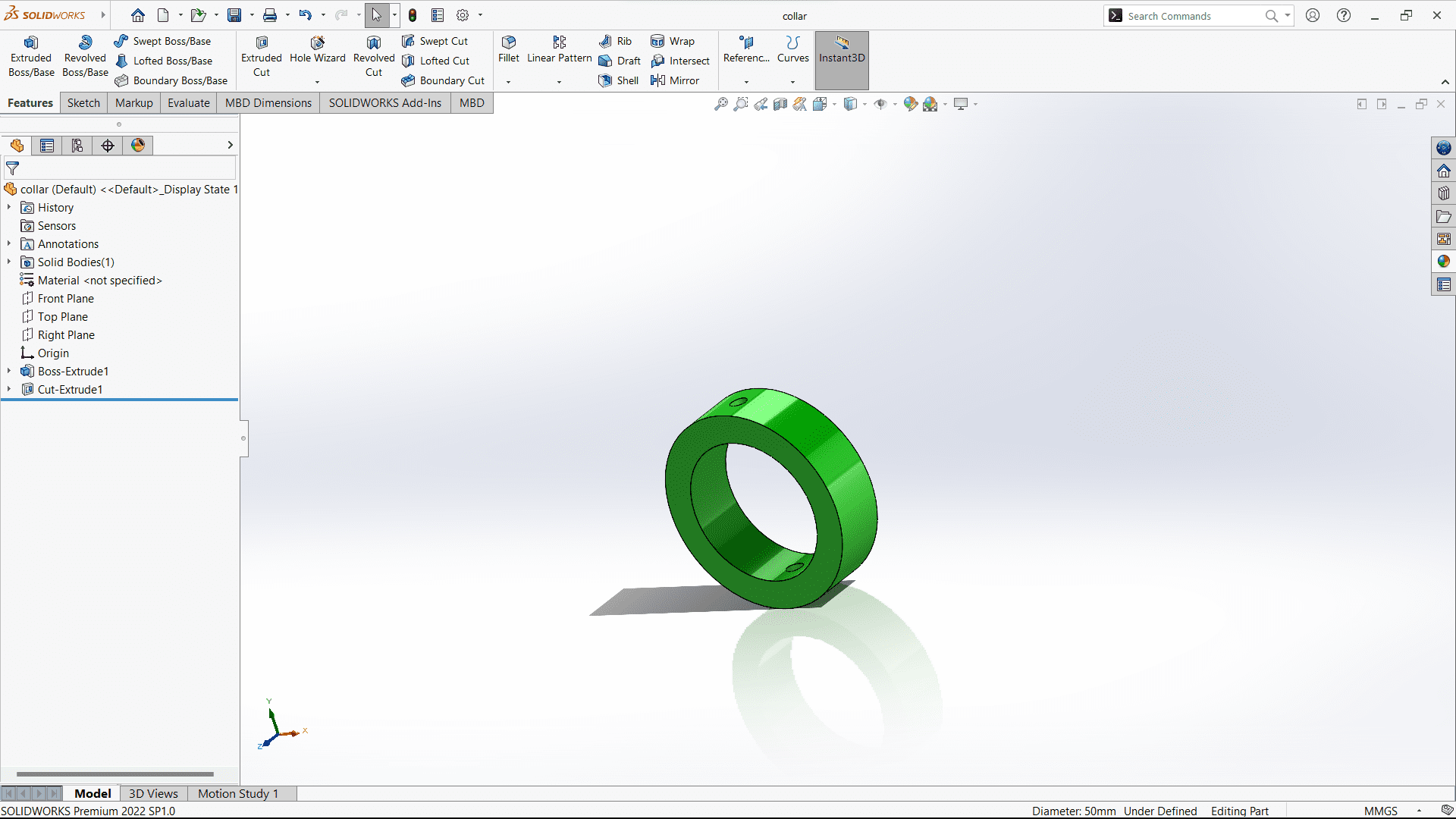
5) Collar:-
The collar has two-hole for passing the taper pin. The collar is placed at the end of the knuckle pin in such a way that the hole meets the hole at the knuckle joint.To draw this part I have used following commands:-
(a) Firstly I selected "Front plane" to draw this part.
(b) I have added circle using "Circle-Radius" command aligned with origin.
(c) "Revolve Boss/Base" command used to add or remove a material by revolving around one or more profiles around centerline.
(d) I used "Vertical" relation to align two or more Entities like line, circle, mid points, corner points, etc. vertically with each other along vertical plane.
(e) "Cut-Extrude" used to remove unwanted material from solid body and provide proper shape to a part.
(g) Finally I used "Edit appearance" command to change its colour into Green colour.
Following picture shows the design of collar.
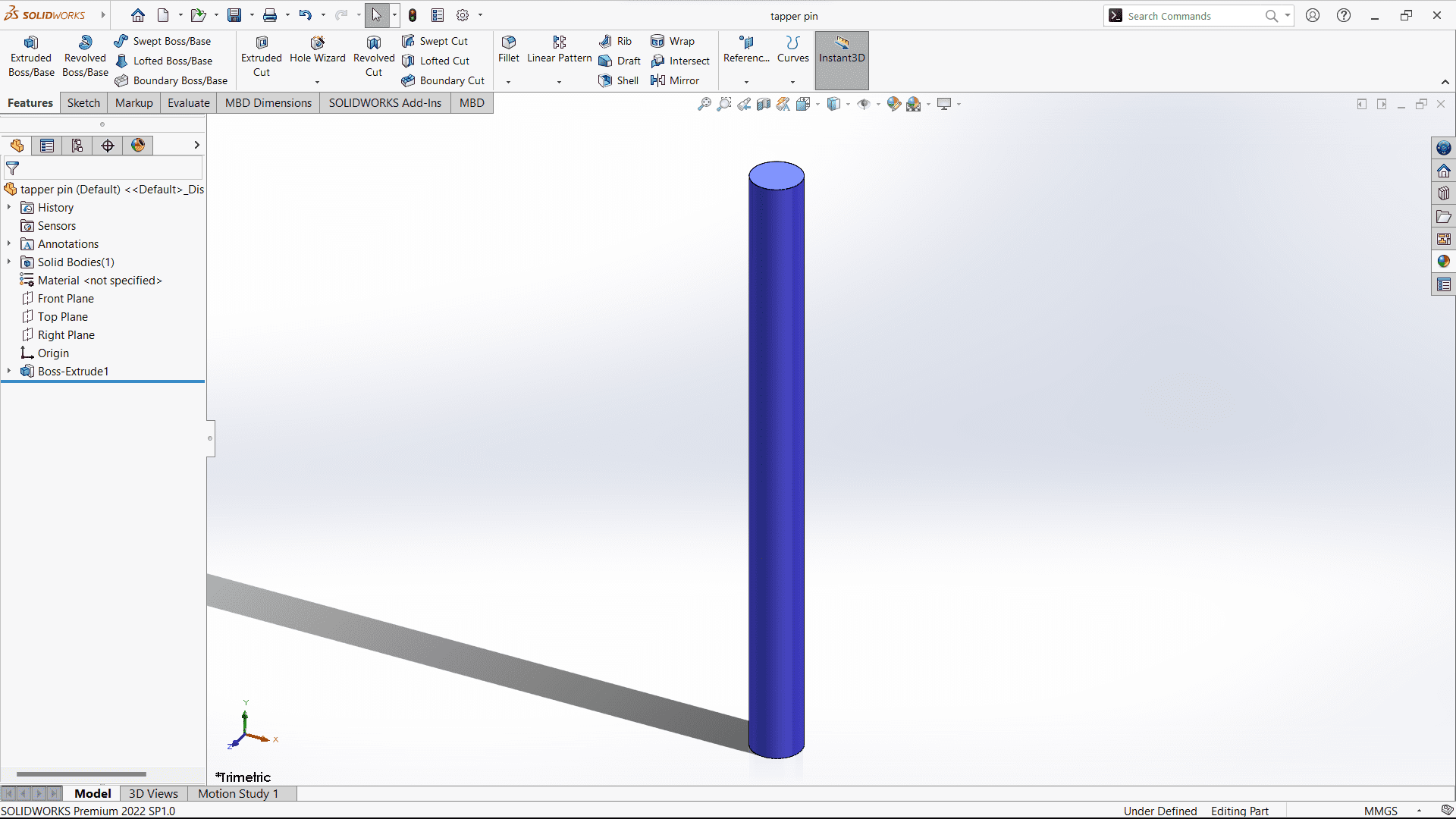
6) Taper Pin:-
The tapper pin is used to tightened the collar and keep them sliding. The pin is subjected to bending moment in addition to shear. To draw this part I have used following commands:-
(a) Firstly I selected "Top plane" to draw this part.
(b) I have added circle using "Circle-Radius" command aligned with origin.
(c) Then using "Boss-Extrude" command to make solid body of drawn geometry.
(d) Finally I used "Edit appearance" command to change its colour into Blue colour.
Following picture shows the design of Tapper pin.
And here is the assembly of all the parts produces knuckle joint.
2. Fusion 360
Fusion 360 is also a 3D CAD software developed by AutoDesk used to create 3D designs, collaborate, manage data, create toolpaths and run simulations to validate the design.
I have created a design of "Basket" in Fusion 360. Following are the steps required:-
(a) First of all, to create a basket bottom layer I have inserted a circle with defined diameter using "Circle" command.
(b) Then, constructed an Offset plane from this circle in upward direction with defined distance.
(c) Inserted one more circle concentric with previous one on the constructed Offset plane.
(d) To make a shape of bowl I used "Loft" command. Loft command creates a smooth surface body that transitions between two or more sketch profiles or planar faces.
(e) Select profile 1 and 2, drag arrow to define direction which causes change in shape of body.
(f) For ring pattern, create Offset plane and used "Project-Solid body" command from "Create sketch".
(g) Repeat step (f) for each Offset plane.
(h) Then used "pipe" command to convert curve into pipe form.
(i) Select operation type different for each part (New component-Pipe, Horizontal pipe-Join, Upper surface edge-New body).
DAY-04
3. AutoCAD
AutoCAD is computer aided design software that is used for drafting and modelling of 2D and 3D drawings.
I have explored this software using "Centre finding method by inscribed and exterior circles" and "Ogee curve". (a) Centre finding method by inscribed and exterior circles:-
1) Draw a circle of radius 10mm.
2) Draw a circle of radius 40mm.
3) Draw a straight line from center of 110mm and vertical 16mm.
4) Draw a circle of 90mm from center and 50mm from a end of horizontal line.
5) Draw a circle at a intersection point where 90mm and 50mm radius circle intersect.
6) Draw one more circle of 54mm radius from center and 94mm circle from end of vertical.
7) Draw a circle at a intersection point where 54mm and 94mm circle meet at downword.
8) Trim unwanted geometry to obtain drawing.
(b) Ogee Curve:-
What is Ogee curve? Ogee curve is a type curve generally used in architecture or designing. The word "Ogee" refers to an edge or a corner. Here is the method to draw Ogee curve in AutoCAD.
1) Take a square of 32mm length.
2) Rotate a square by 45deg.
3) Offset a square by 6mm inside.
4) Draw a horizontal straight line of 160mm and vertical line downward 52mm to get center of a polygon.
5) Select polygon of 5 sides inscribed in the circle of radius 22mm.
6) Rotate pentagon and offset pentagon by 6mm inside.
7) Draw a line joining square and pentagon.
8) Break the line in two parts from center.
9) Draw a straight line from square downward.
10) Offset the break line in upward.
11) Draw a perpendicular to both the lines.
12) Expand the perpendicular line to downward.
13) Then draw a circle.
14) Do similar process in opposite side of pentagon.
15) Trim the unwanted portion.
16) Now offset the curve from both sides by 11mm.
17) Expand it upto end.
18) Draw a line at a center of a curve and offset it by 5.5mm.
19) Take "(Axis,End)" command and draw a eclipse.
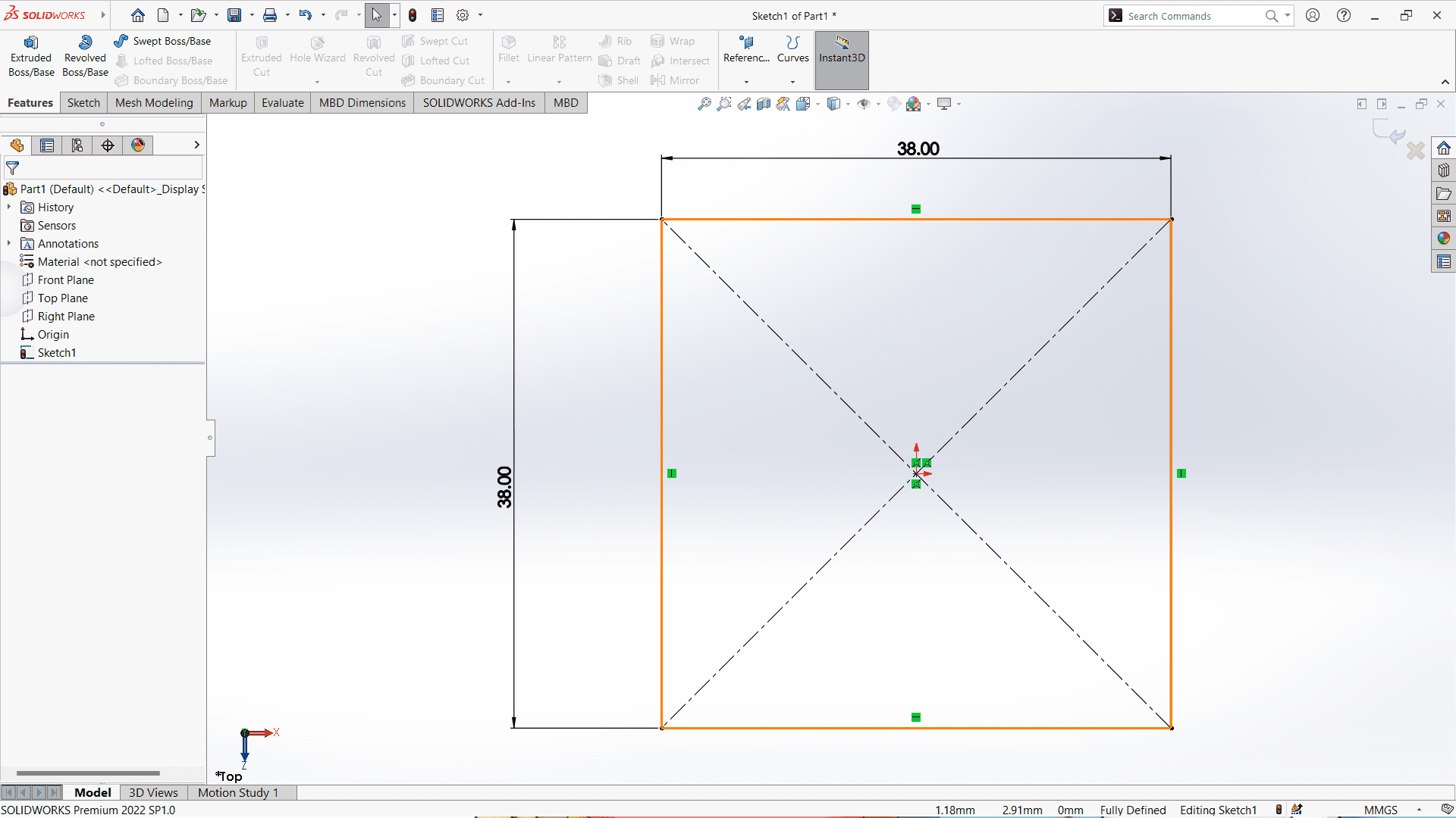
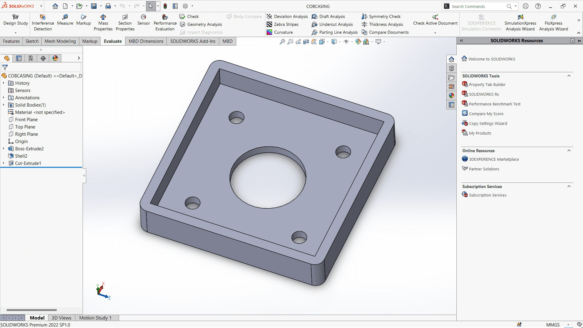
Now, I decided to design something for my final project. In my final project, I want to use COB LED light on the helmet. So here I havee a design a casing for that COB LED light. Here are the steps for designing -
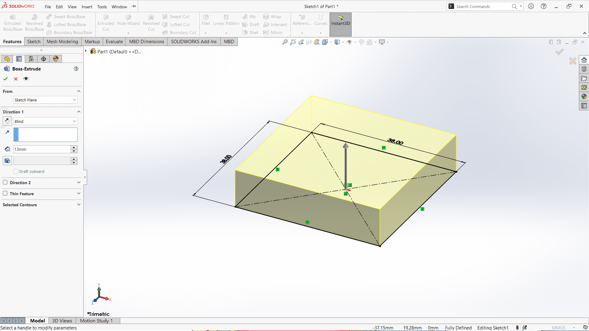
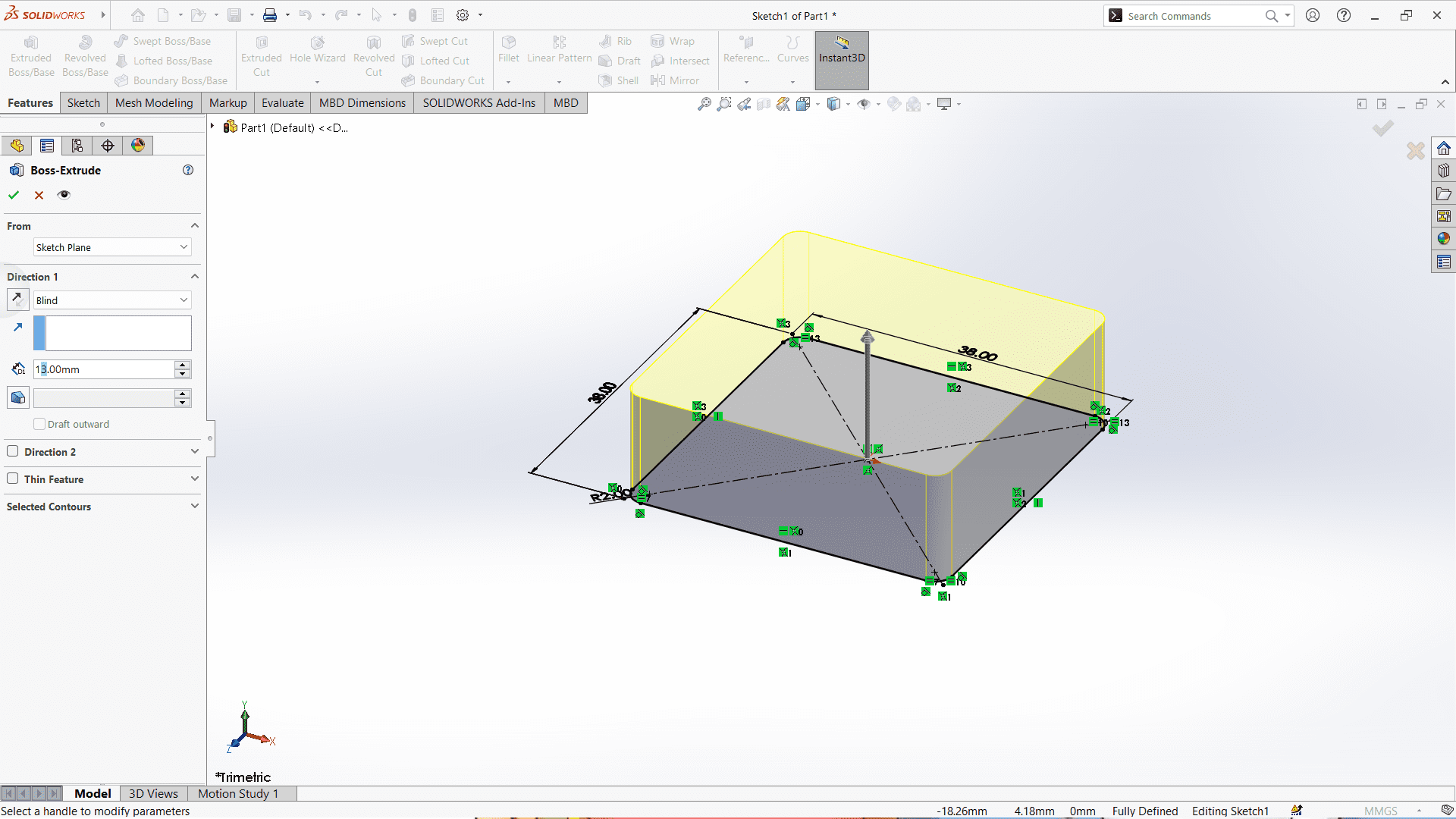
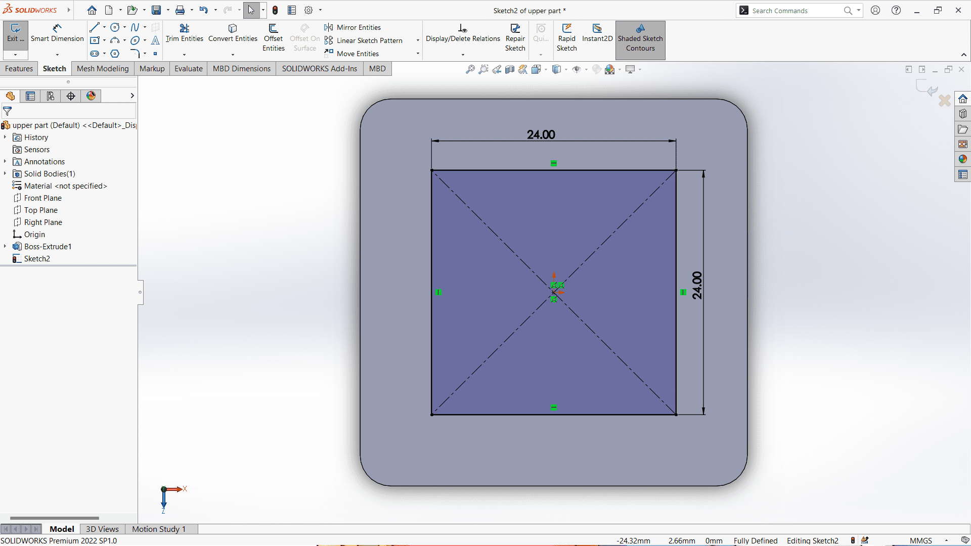
Firstly, select the plane for design. Here, I have selected "Top Plane" for the design. Then, I drew the rectangle using rectacngle feature.
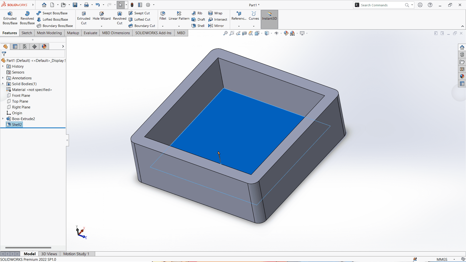
Then, I used "Boss-Extrude" feature to make a solid body.
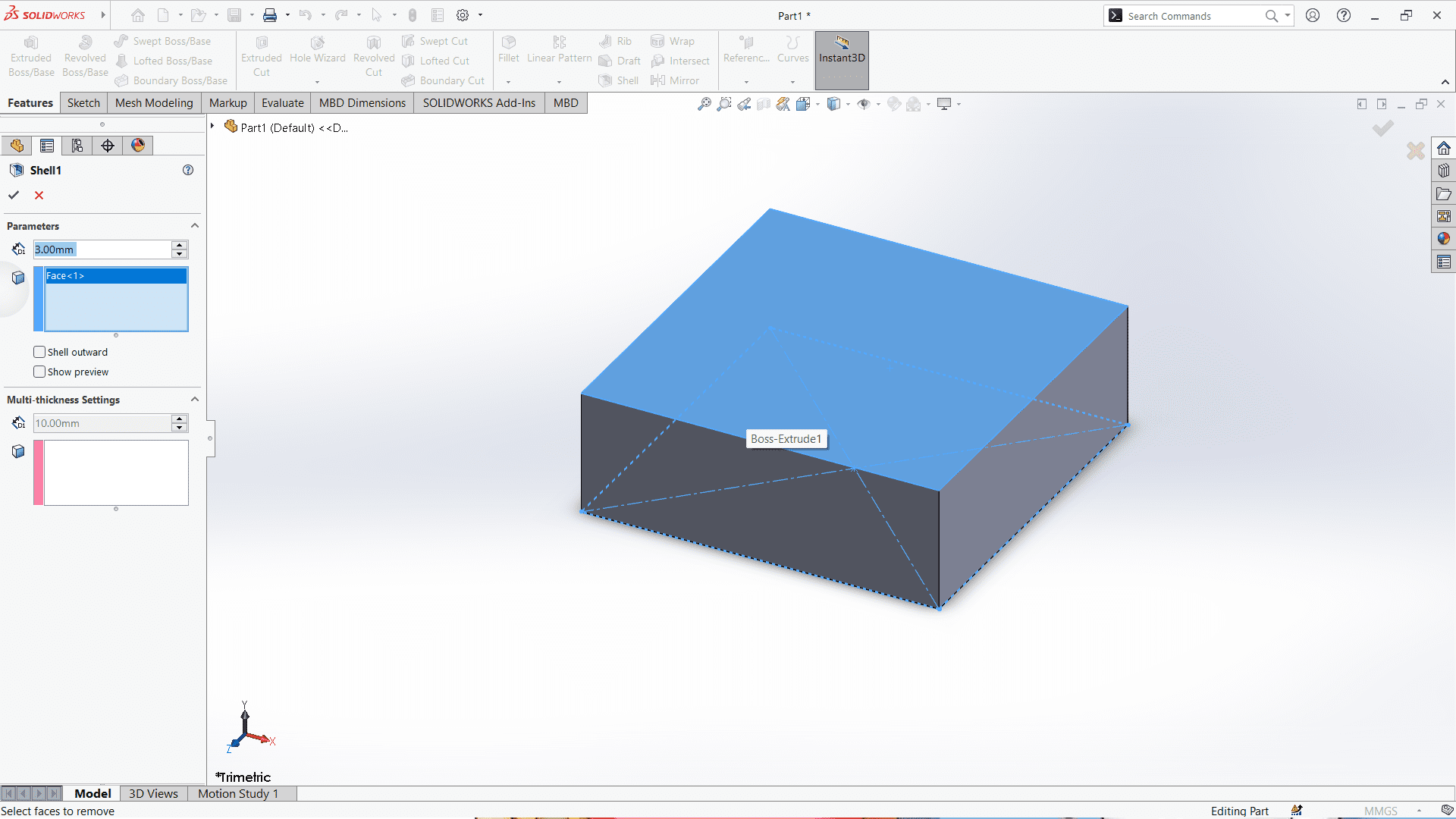
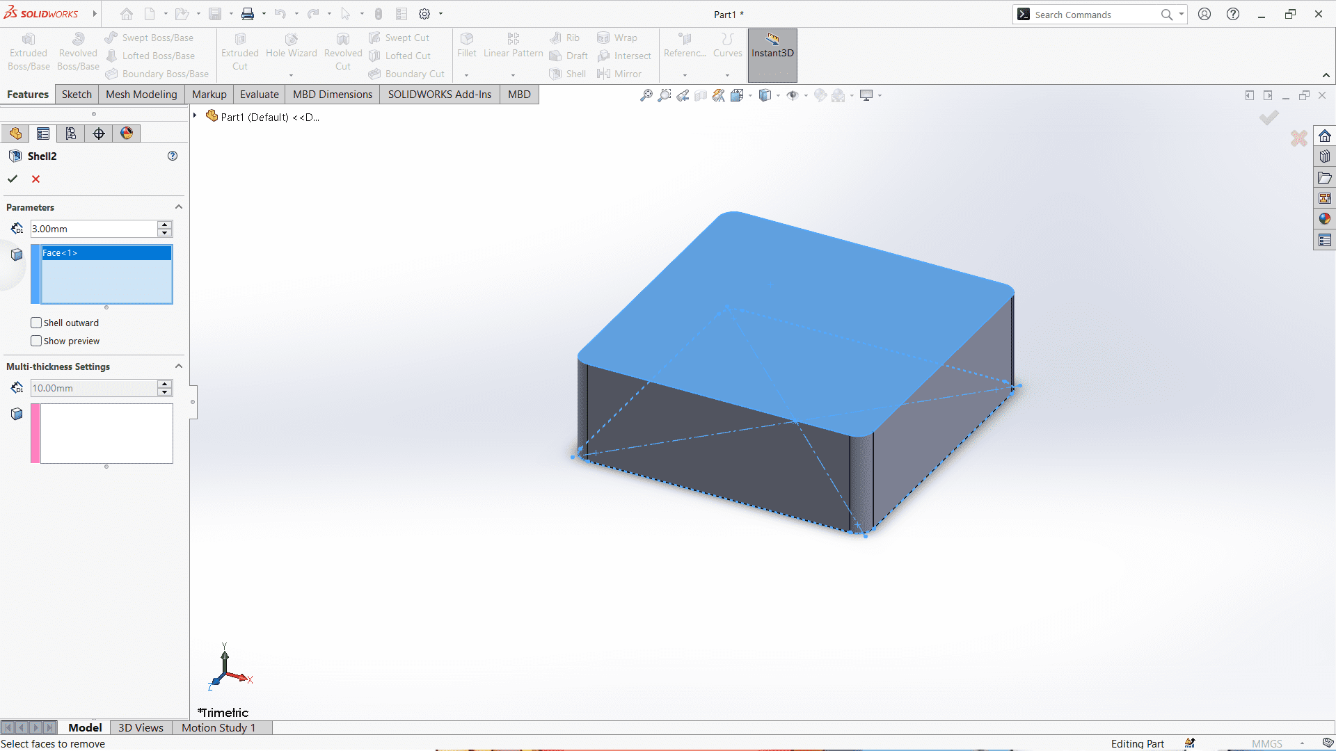
Here is used "Shell" feature to convert it into a box shape body.
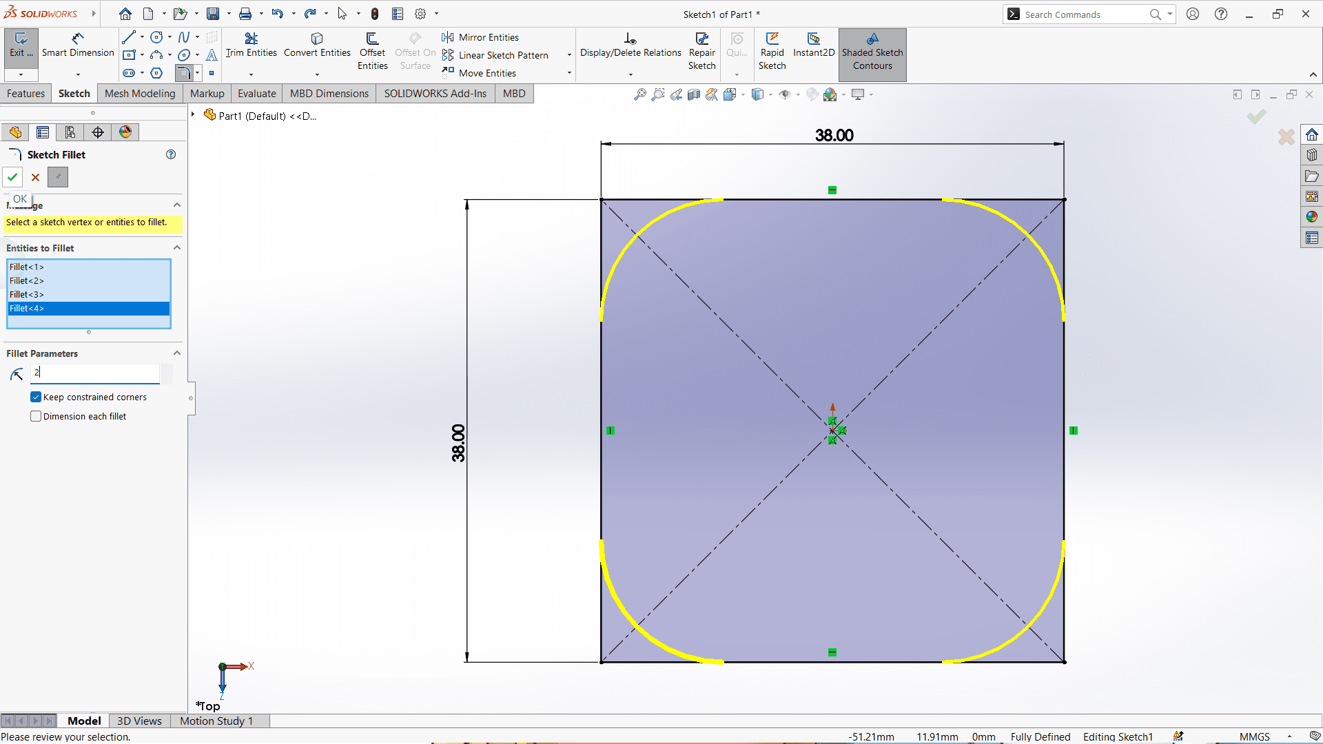
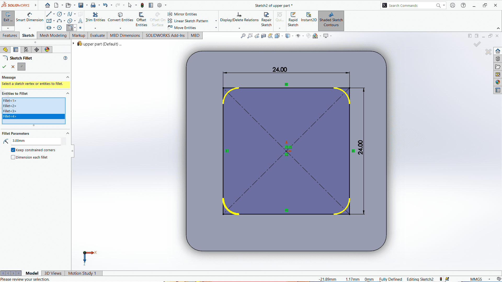
Then, I used "Fillet" feature to give fillet to the corner of the box to make it smooth.