Week 9
Output Devices
Group Assignments
In the group assignment we was able to measure the power consumption of an mini Stepper Motor. By understanding Electrical Parameters first thus voltage(V), current(I) and power(p) then measuring techniques such as a Multimeter but also calculation that gets you to understand the ways devices as oscilloscopes and power meters concludes to certain numbers. Power consumption can vary based on the load the motor is driving, so its always better to measure under different load conditions to get a comprehensive understanding.
I2C Serial Interface 1602 LCD Module
For this week i choose to get around the lcd display so that i familiarize myself with using it due to the fact that i'll be needing it for my final project. So i was able to find this is the type of LCD in our lab; this I2C interface 16x2 LCD display module, a high-quality 2 line 16 character LCD module with on-board contrast control adjustment, backlight and I2C communication interface. For Arduino beginners, no more cumbersome and complex LCD driver circuit connection. The real significance advantages of this I2C Serial LCD module will simplify the circuit connection, save some I/O pins on Arduino board, simplified firmware development with widely available Arduino library. The picture was sourced from here
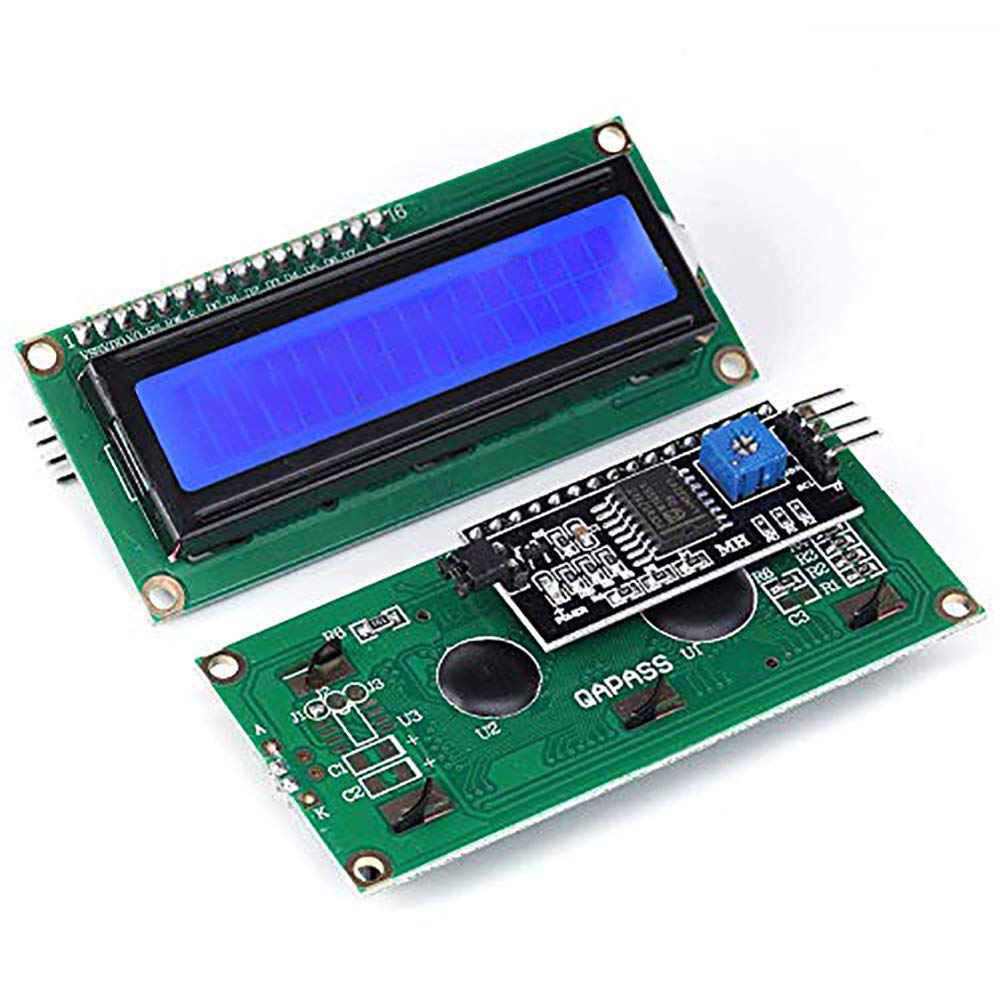
Brief data
- Compatible with Arduino Board or other controller board with I2C bus.
- Display Type: Negative white on Blue backlight.
- I2C Address:0x38-0x3F (0x3F default)
- Supply voltage: 5V
- Interface: I2C to 4bits LCD data and control lines.
- Contrast Adjustment: built-in Potentiometer.
- Backlight Control: Firmware or jumper wire.
- Board Size: 80x36 mm
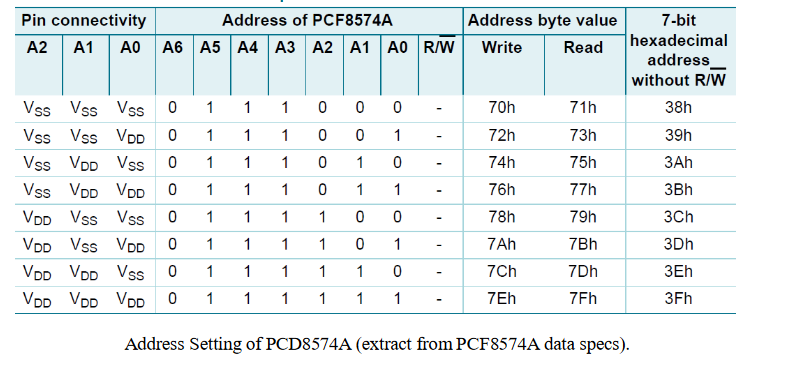
Using the LCD piggy-back board, desired data can be displayed on the LCD through the I2C bus. In principle, such backpacks are built around PCF8574 (from NXP) which is a general purpose bidirectional 8 bit I/O port expander that uses the I2C protocol. The PCF8574 is a silicon CMOS circuit provides general purpose remote I/O expansion (an 8-bit quasi-bidirectional) for most microcontroller families via the two-line bidirectional bus (I2C-bus). Note that most piggy-back modules are centered around PCF8574T (SO16 package of PCF8574 in DIP16 package) with a default slave address of 0x27. If your piggy-back board holds a PCF8574AT chip, then the default slave address will change to 0x3F. In short, if the piggy-back board is based on PCF8574T and the address connections (A0-A1-A2) are not bridged with solder it will have the slave address 0x27.
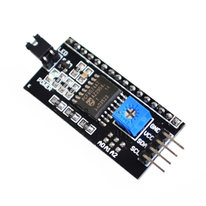
More info on this can be found here
At first you need to solder the I2C-to-LCD piggy-back board to the 16-pins LCD module. Ensure that the I2C-to-LCD piggy-back board pins are straight and fit in the LCD module, then solder in the first pin while keeping the I2C-to- LCD piggy-back board in the same plane with the LCD module. Once you have finished the soldering work, get four jumper wires and connect the LCD module to your microcontroller as per the instruction given below.
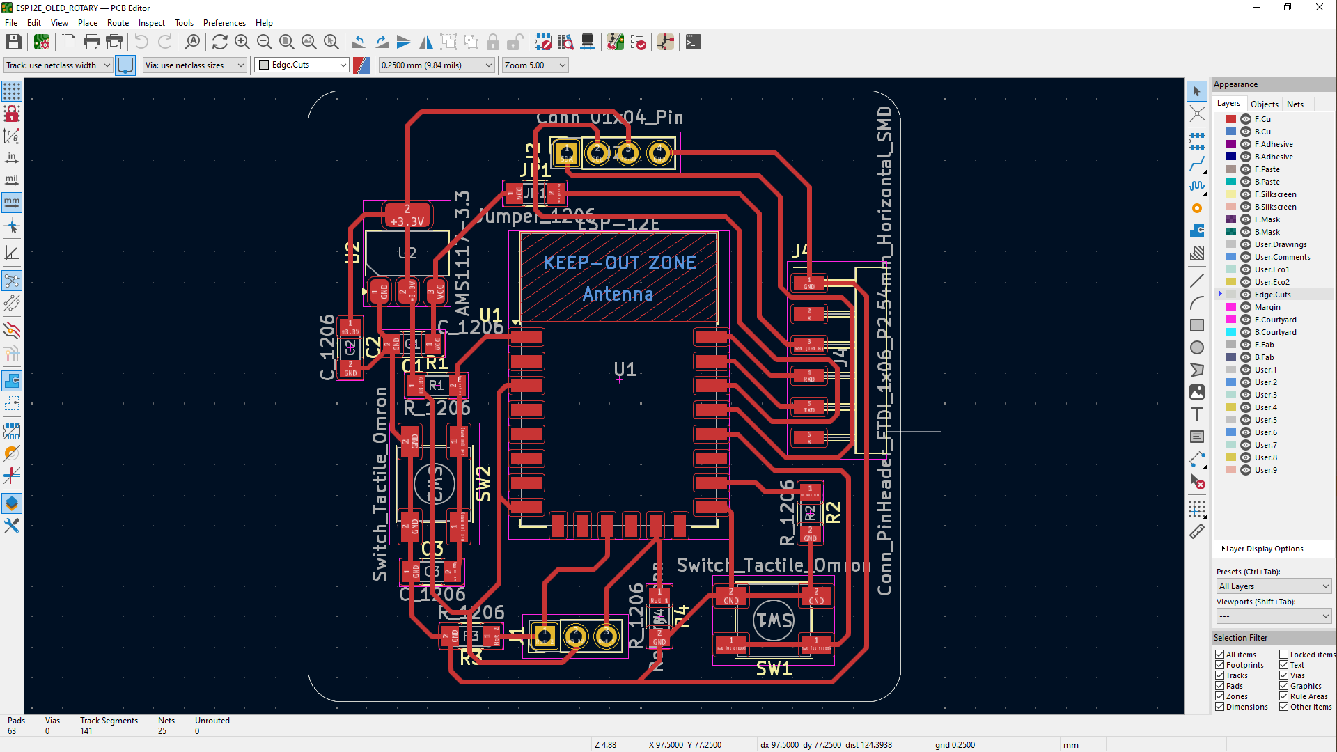
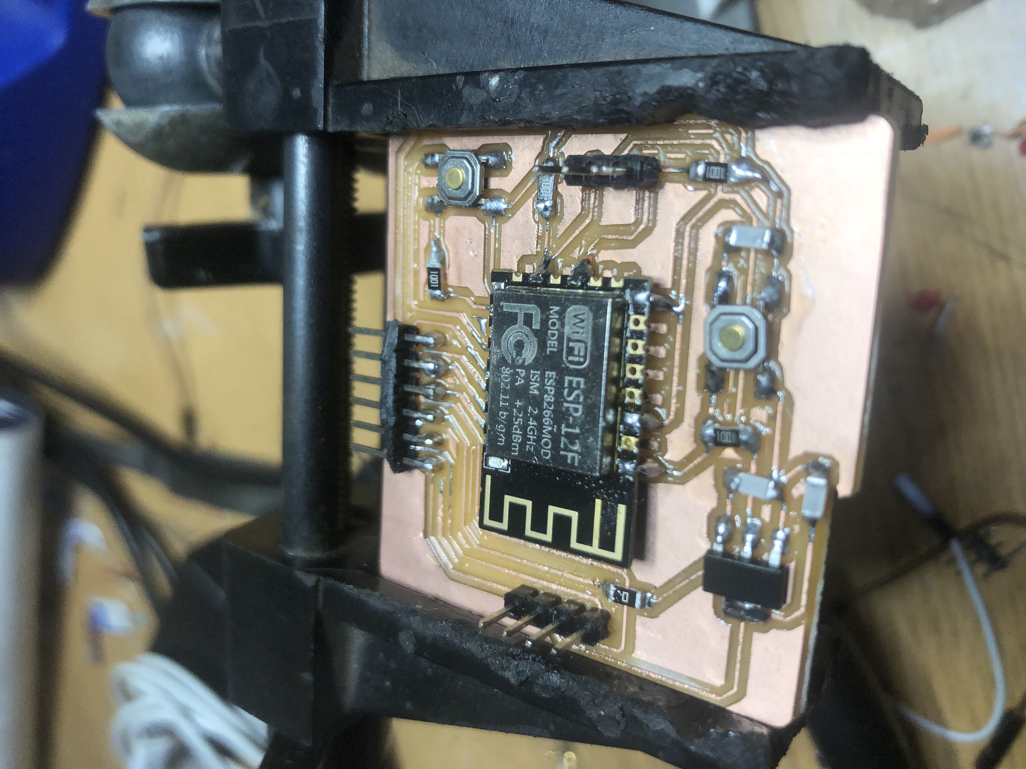
So at first, i used a ESP8266MOD As a micro controller for this assignment information about this microcontroller can be found hereand i chooose to use this microcontroller because i had an isuue my xiao esp32C3 stops working and with the assignments due i had to use what was available and efficient at my disposal so i started using it with designing a circuit first and adding values and footprints, i moved on to generate files to mill the pcb then solder components onto the pcb then start adding codes to pcb
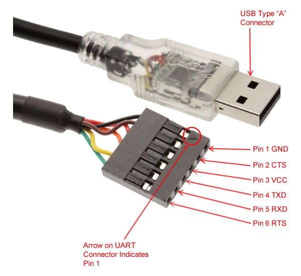
So after that i gathered some research on how i can connect my microcontroller to the editor in this case i used the arduino ide so for connecting my pcb board to the editor so that i can program the microcontroller to use the output device. I used the TTL-232R-5V This cable is used to transmit and receive data between computer and external devices such as microcontrollers, Arduino, development modules (Bluetooth, GPS, GSM, etc). Most importantly, FTDI cable comes with an internal mounted electronic circuit which uses FTDI FT232R chip. This FTDI chip converts USB data to serial and vice versa. In other words, this cable provides an effective and cheap solution to connect TTL serial interface to USB. More info about the FTDI cable can be found here. further more i continued with plugging the cable on the pin headers that were left to link the ftdi cable with the pcb and the other end of the cable to be linked with the computer. Now on the end of the pcb, we need to connect the FTDI cable's end accordingly to the set of the pin headers using the circuit itself and the picture below as well
For this experiment it is necessary to download and install the “Arduino I2C LCD” library.
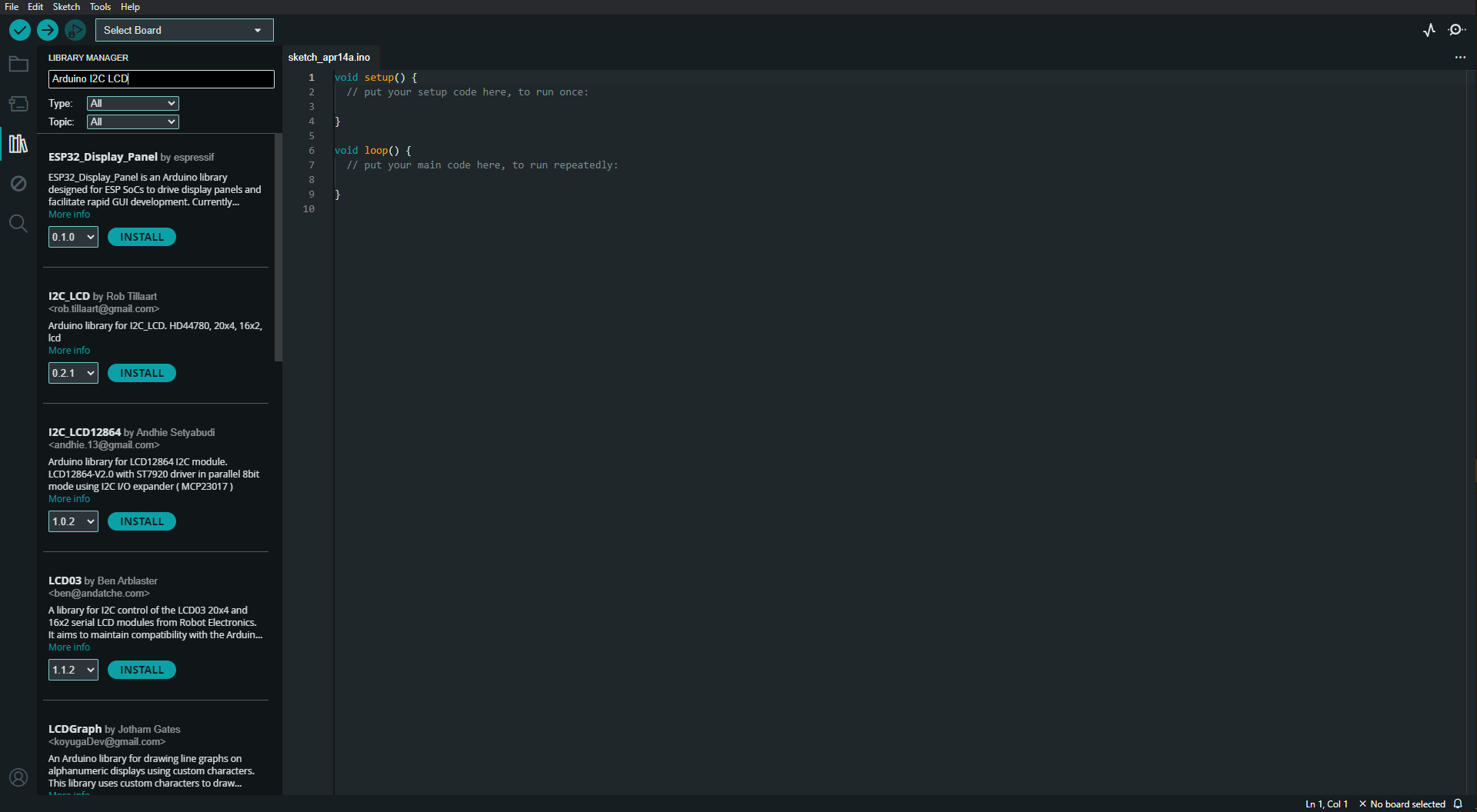
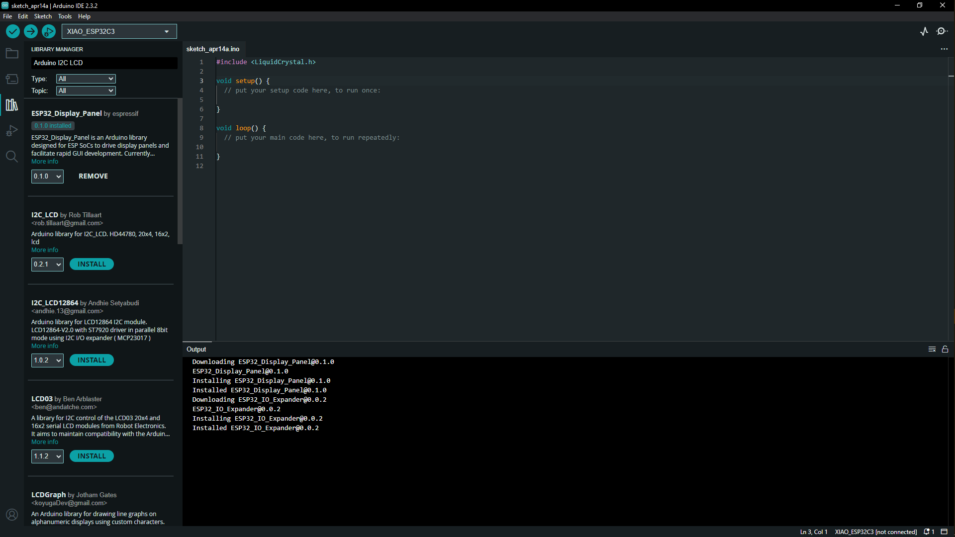
Below the picture shows adding the LCD display library being added to help the LCD be connected with ESP8266 board.
Codes
At first i used examples codes that are in the library by going to file-examples-liquidCrystal_I2C-helloworld this opened up the codes that are in the picture below so i went on to upload the program into the microcontroller which takes a few seconds the codes are done uploading you can unplug the ftdi cable from the computer and adjust the display contrast on the back of the piggy back board for the characters in the screen to be well visible below
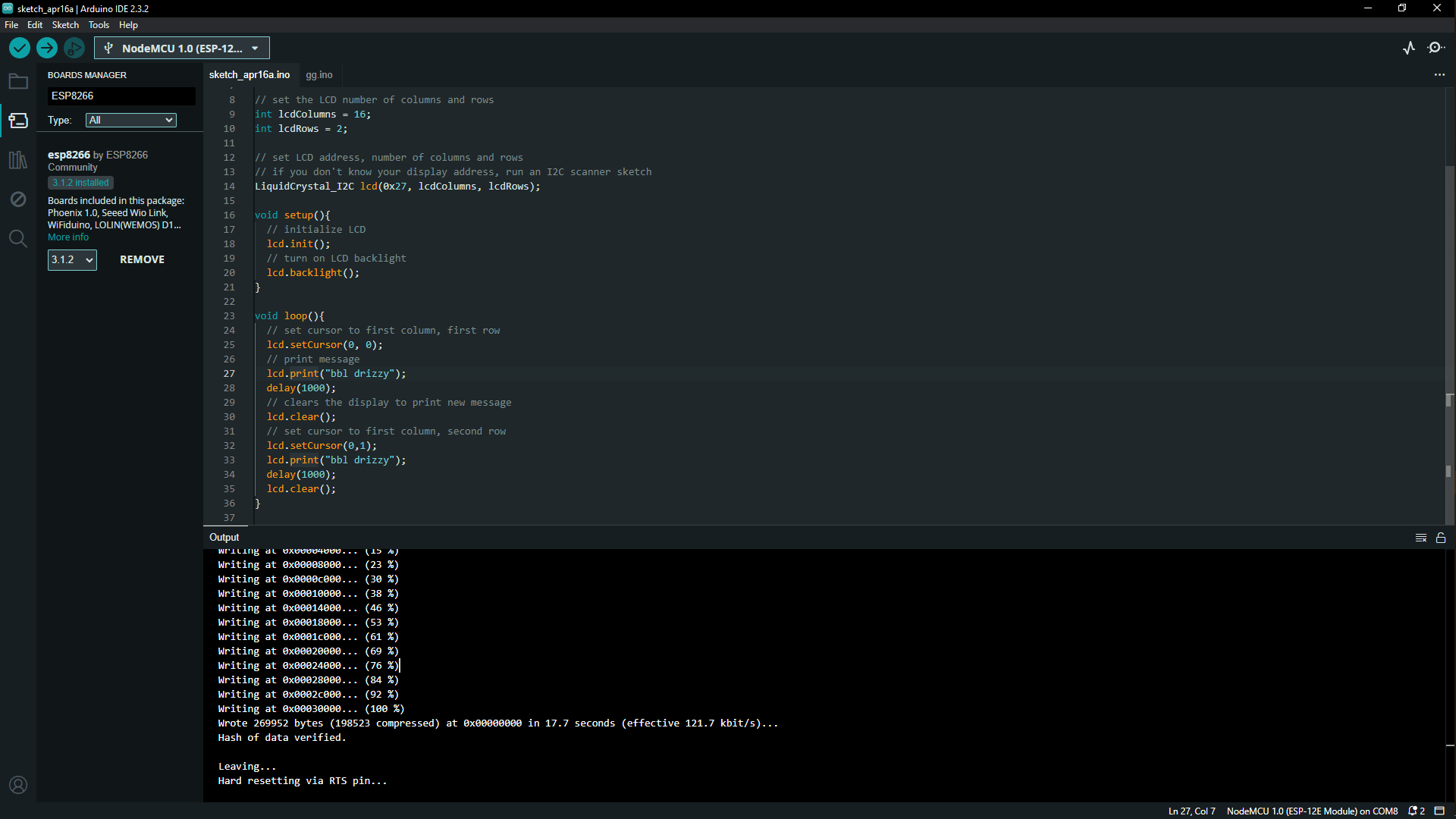
#include

// set the LCD number of columns and rows
int lcdColumns = 16;
int lcdRows = 2;

// set LCD address, number of columns and rows
// if you don't know your display address, run an I2C scanner sketch
LiquidCrystal_I2C lcd(0x27, lcdColumns, lcdRows);

void setup(){
  // initialize LCD
  lcd.init();
  // turn on LCD backlight
  lcd.backlight();
}

void loop(){
  // set cursor to first column, first row
  lcd.setCursor(0, 0);
  // print message
  lcd.print("bbl drizzy");
  delay(1000);
  // clears the display to print new message
  lcd.clear();
  // set cursor to first column, second row
  lcd.setCursor(0,1);
  lcd.print("Hello world");
  delay(1000);
  lcd.clear();
}