Week 11
Input Devices
The group assignments can be found here
For this week i focused on using the a rotary encoder as it was to be part of my project then i went on to design a board to control the rotary encoder. The board was initially designed in the in the electronics deisign week with intentions of adding both the input and output Devices.
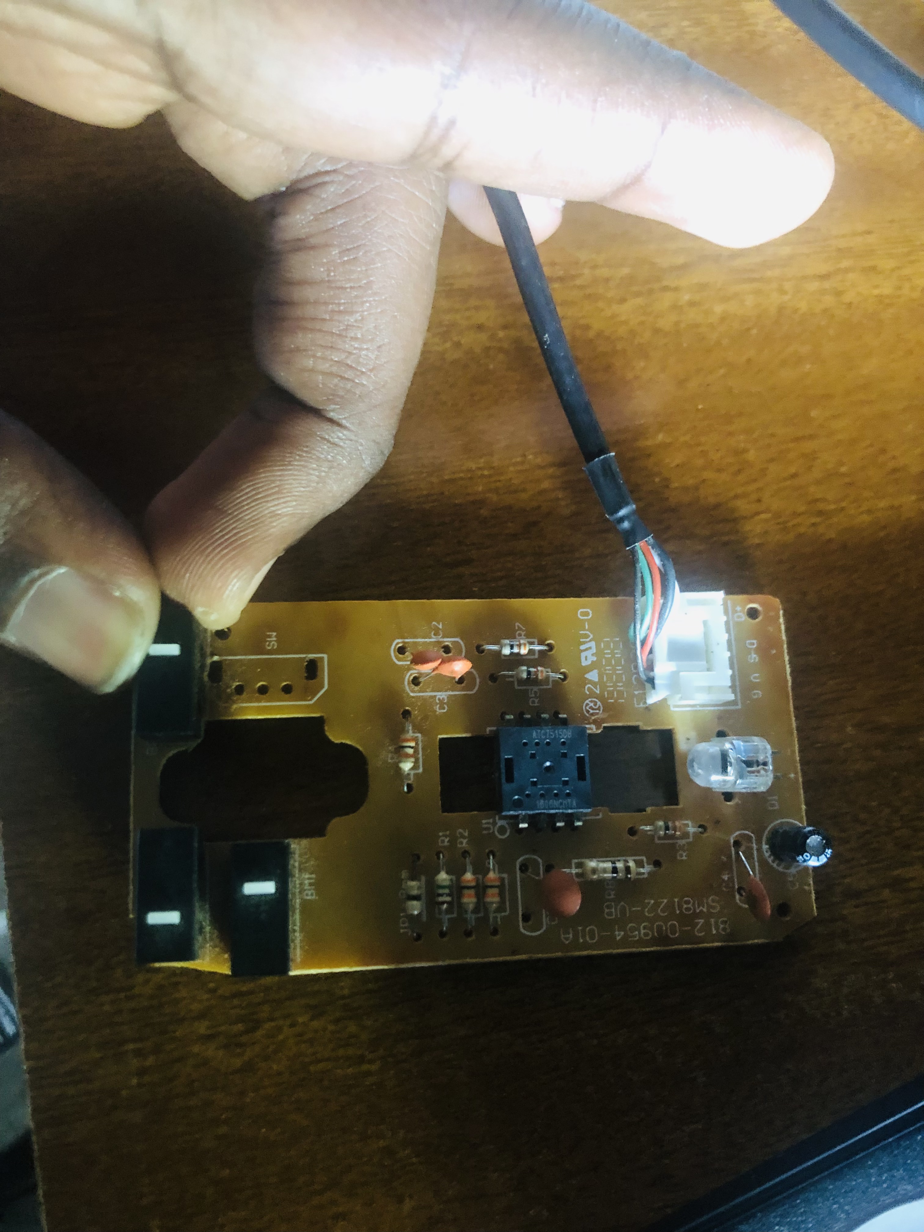
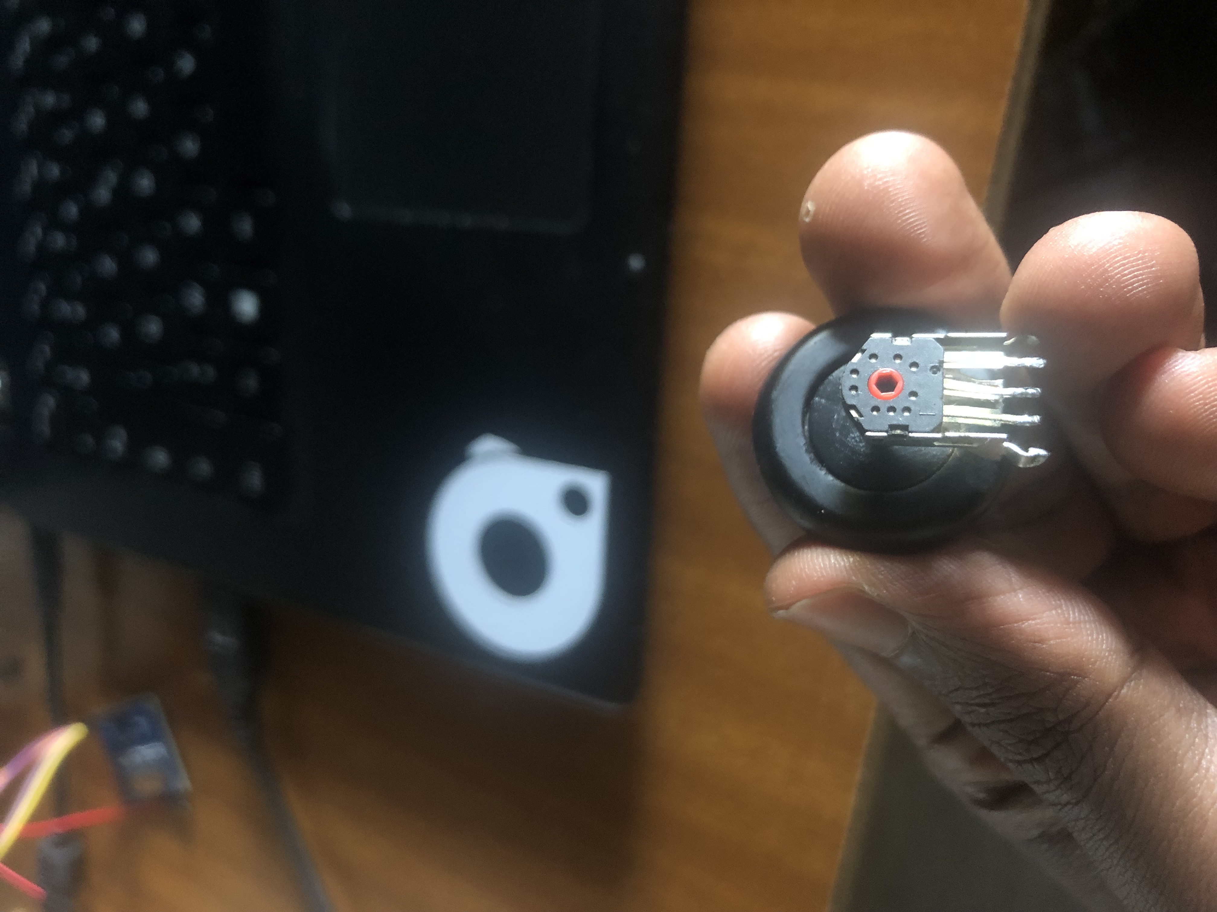
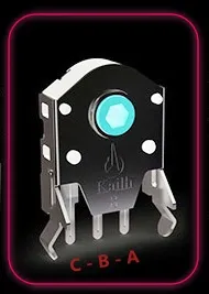
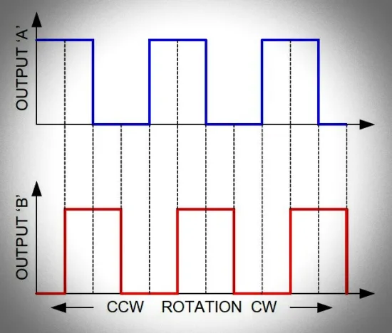
Initially my intentions for the rotary encoder was to use it for a test to see what the outcomes of my project would be so i went on and took it off of a no longer working computer mouse. This is a quick view of the circuit board of my old Chinese usb optical mouse. As you can see, there’s a small (9mm) mouse scroll wheel rotary encoder and a single chip optical mouse sensor – MX8733. As usual, the rotary encoder has three pins. The data pins are wired directly to pins 1 and 8 of the MX8733 chip. I lifted off the rotary encoder from the circuit board as it was the only thing needed for my project. Below you can see the pinout drawing of that 24-step, 9mm mouse scroll wheel rotary encoder. As shown above, the rotary encoder has two data pins (A-B) and a common pin (C). Basically a rotary encoder has two outputs, A and B, that are offset in time as the shaft rotates, so the microprocessor can determine the direction and amount of rotation applied to the encoder.
The below figure depicts the anticipated voltage wave forms as the rotary encoder is turned.
Now there’s a circuit i had designed using kicad that would be supplied by a ftdi-usb-to-serial-converter-cable or TTL-232R-5V which supplies 5v to the cicuit connected to a voltage regulator to convert the 5v to 3.3V due to peripherals using a 3.3V, we have capacitors connected for filtering the voltage and pull up resistors will ensure that the configured pin isn't in a high state, while also using a low amount of current(more on this, we also have two switches one for booting the programm on the microcontroller, the other for resetting the microcontroller. Below, the rotary encoder pins are identifiable by the yellow rectangular box, below it, the png file to be used on MODS CE website to generate the milling files for pcb.
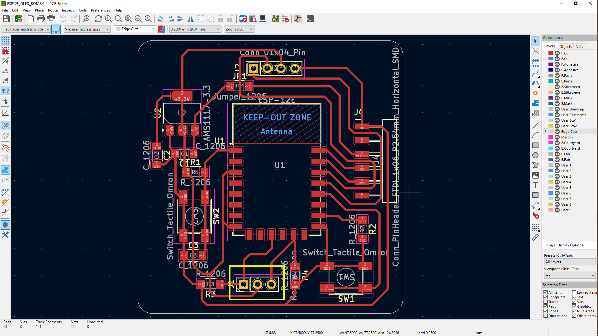

In this circuit i used the ESP8266-12F as a microcontroller, reason is the xiao esp32C3 i was using had a problem with its serial so i opted for this but also the ESP8266 which is a complete and self-contained WiFi network solution that can operate independently or as a slave running on other host MCUs. The ESP8266 is capable of booting directly from an external flash memory when it is powered by an application and is the only application processor in the device. The built-in cache helps improve system performance and reduce memory requirements. In another case, the ESP8266 is responsible for wireless Internet access. When it comes to the task of the WiFi adapter, it can be added to any micro controller-based design. The connection is simple and easy, just by SPI / SDIO interface or I2C / UART port. The ESP8266's powerful on-chip processing and storage capabilities allow it to integrate sensors and other application-specific devices through the GPIO port, minimizing system resources during minimal up-front development and operation.
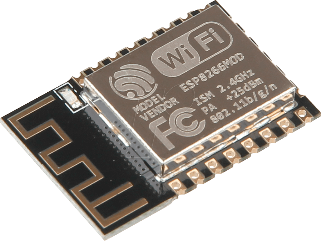
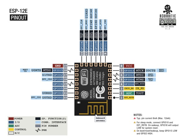
After soldering the components onto the board i opened the arduino IDE whiwh was the text editor of choice in programming up to this point, then pressed and hold the boot button then plugged the ftdi-usb-to-serial-converter-cable to my pc. I had wrote some codes to be readable on the OLED MODULE and the movements of the rotary encoder to be added/readable on the oled screen later on.
CODES
The codes below were the ones i used for both devices.
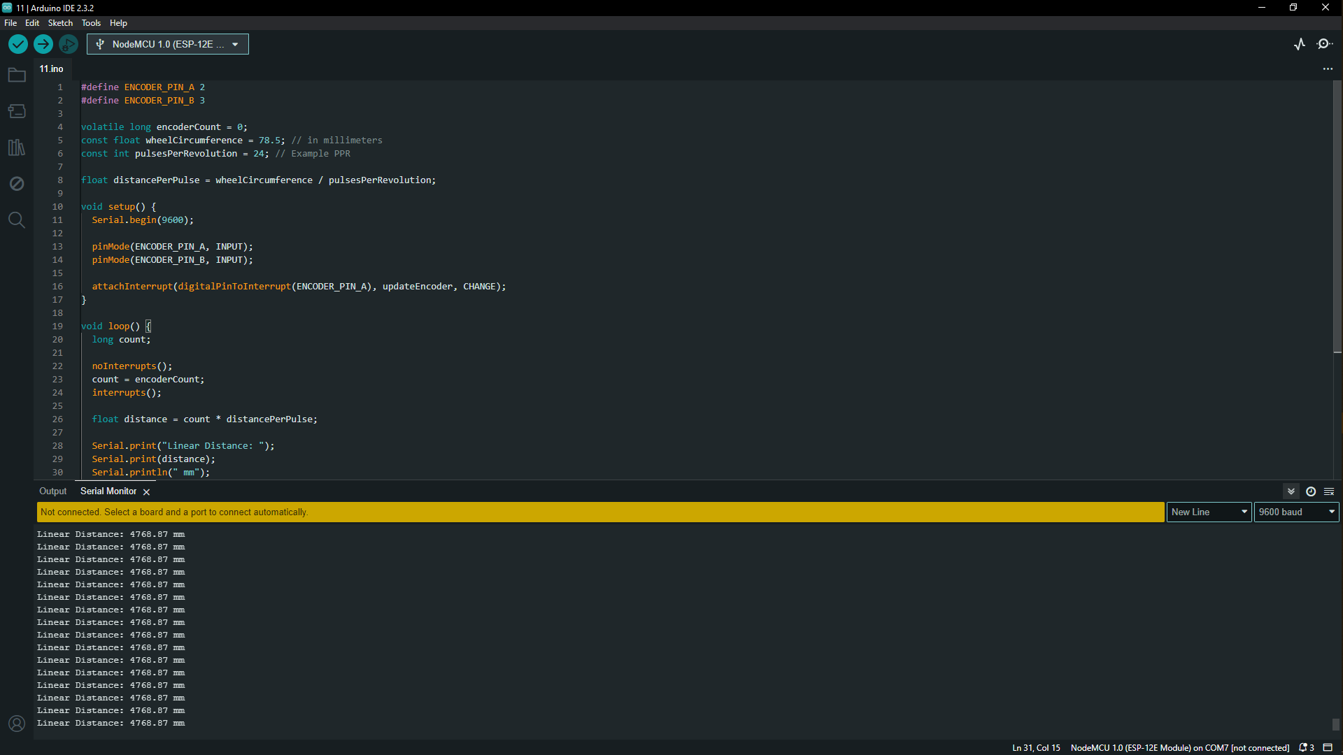
      #define ENCODER_PIN_A 8
      #define ENCODER_PIN_B 7

      volatile long encoderCount = 0;
      const float wheelCircumference = 78.5; // in millimeters
      const int pulsesPerRevolution = 24; // Example PPR

      float distancePerPulse = wheelCircumference / pulsesPerRevolution;

      void setup() {
        Serial.begin(9600);

        pinMode(ENCODER_PIN_A, INPUT);
        pinMode(ENCODER_PIN_B, INPUT);

        attachInterrupt(digitalPinToInterrupt(ENCODER_PIN_A), updateEncoder, CHANGE);
      }

      void loop() {
        long count;

        noInterrupts();
        count = encoderCount;
        interrupts();

        float distance = count * distancePerPulse;

        Serial.print("Linear Distance: ");
        Serial.print(distance);
        Serial.println(" mm");
        delay(1000);
      }

      void updateEncoder() {
        int stateA = digitalRead(ENCODER_PIN_A);
        int stateB = digitalRead(ENCODER_PIN_B);

        if (stateA == stateB) {
          encoderCount++;
        } else {
          encoderCount--;
        }
      }
so due to my board that i had used being completely unusable i decided to re use the xiao ESP32-C3 since i had used it before so i connected the encoder pins to the XIAO_ESP32C3 and it wasn't the first time using it so the board was already installed in the arduuino IDE all i had to do is configure my rotary pins and load the current codes in the microcontroller