Índice
Model 2D
During this week, I focused on modeling both in 3D and 2D the design of the sketch that will be submitted as part of my final project. I carried out the modeling practice using various drawing and design programs to observe the benefits of each one. For 2D, I utilized Adobe Illustrator and Good Notes, while for 3D modeling, I worked with FreeCAD and SolidWorks. This allowed me to compare and assess the advantages of each program and their suitability for different forms.
Software 1: GoodNotes
GoodNotes is an iPad software used for note-taking, allowing you to use both the keyboard and the Apple Pencil for support. It is also very useful for creating drawings; however, I believe that the results of the drawings are more like a preliminary sketch, or when you want to define which shapes you will ultimately use.
Step 1: Open GoodNotes
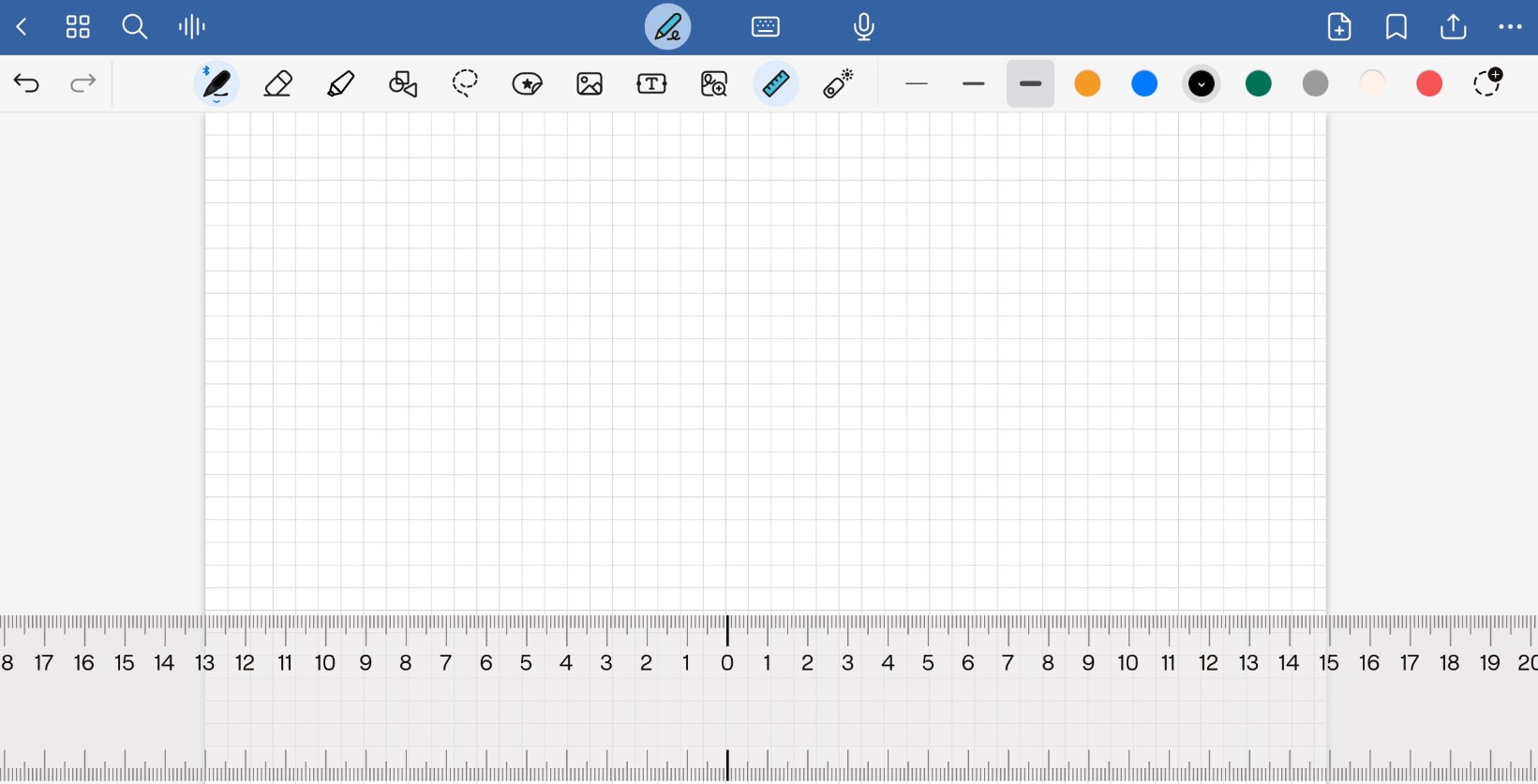
The first step is to open the software and create a new document. To help me create straight strokes, I decided to use a grid and a ruler. (Fig. 1).
Fig. 1. Drawing ruler
Step 2: Shape Tool
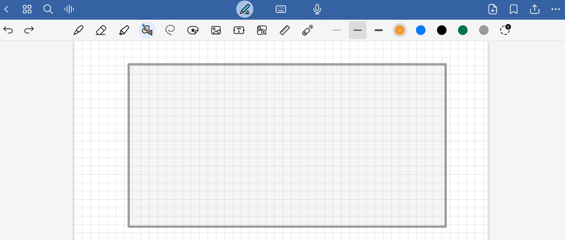
Once you have the grid and the ruler selected, you choose the shapes tool and trace your initial figure, in my case, a rectangle. (Fig. 2).
Fig. 2. Shape tool
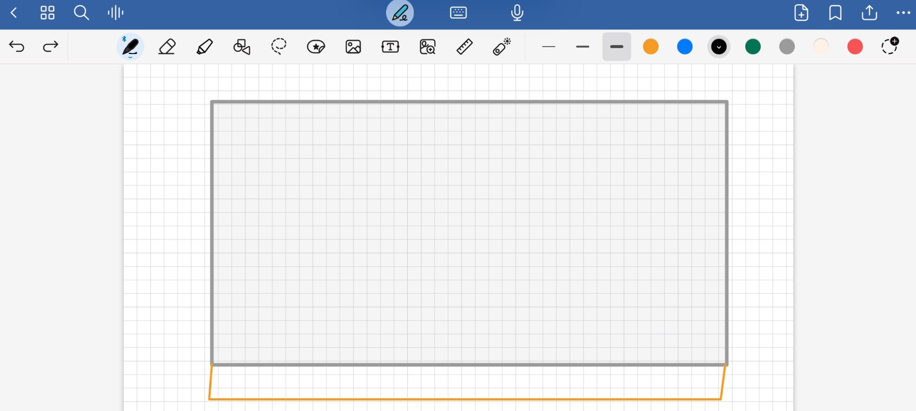
Step 3: Add a smaller rectangle in length
Adjacent to the large gray rectangle, create a smaller rectangle in length but with the same width. Add some angled lines, as the idea is for this to be a small ramp. This is the front of your sketch. (Fig. 3).
Fig. 3. smaller rectangle in length.
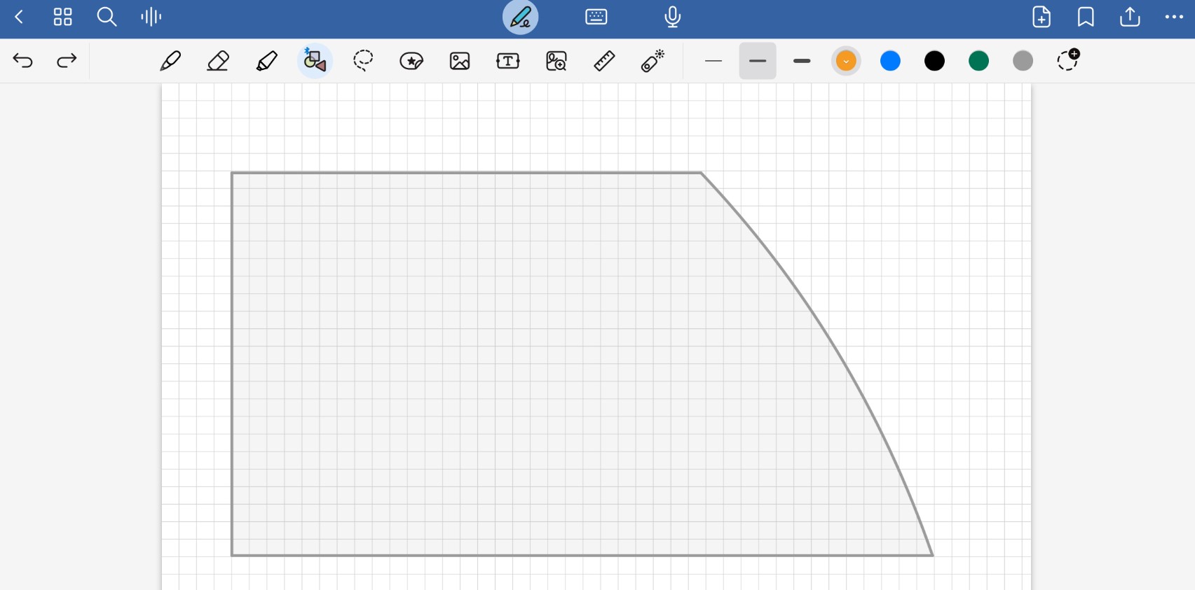
Step 4: Left side
On a new sheet, add a new shape; this time, it should be a rectangle, but on the right side, leave an arc, as this is where it will be assembled to the other figure. (Fig. 4).
Fig. 4. Rectangle with an arc.
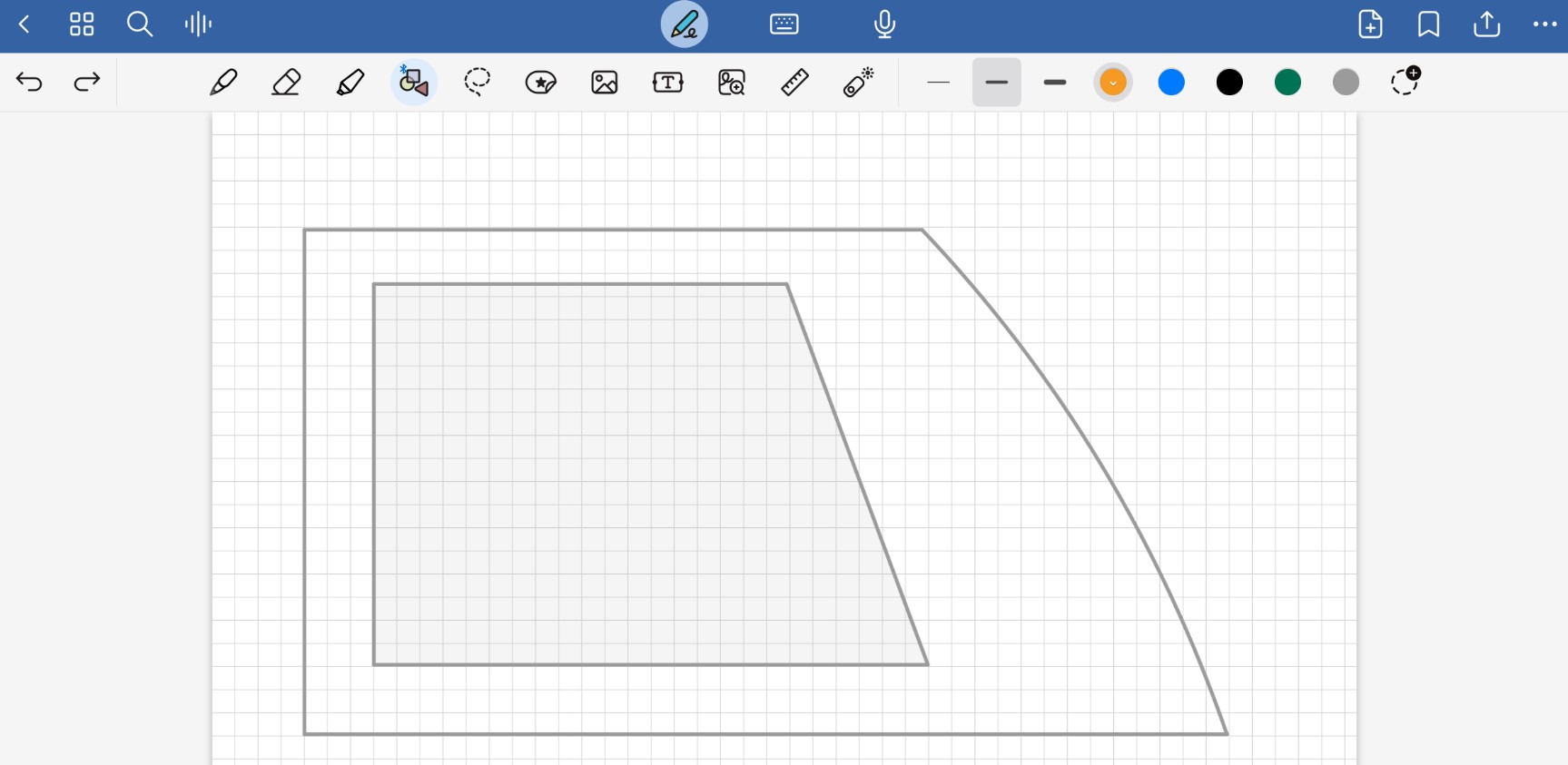
Step 5: Smaller scale
Add the same shape, but in a smaller scale, in the center of the previous one; later, this will serve as a cutout to reduce the weight of the robot. (Fig. 5).
Fig. 5. Cutout to reduce the weight of the robot.
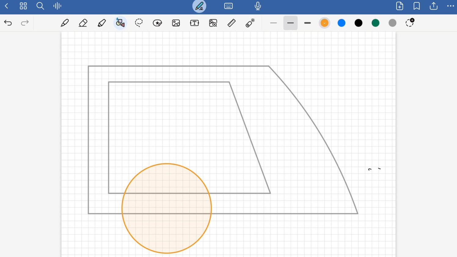
Step 6: Wheels
In the design, add a orange circle at the bottom, which will serve as one of our wheels. Duplicate this design in mirror to have both sides of the robot. (Fig. 6).
Fig. 6. Left side of the robot.
Software 2: Illustrator
The next application used for 2D modeling is from the Adobe suite and is called Illustrator. This application allows for the creation of vector drawings, which enables precise visualization of the strokes and the ability to scale them as needed. It is one of my favorite programs due to my greater experience with it and the variety of tools it provides.
Step 1: Open new document
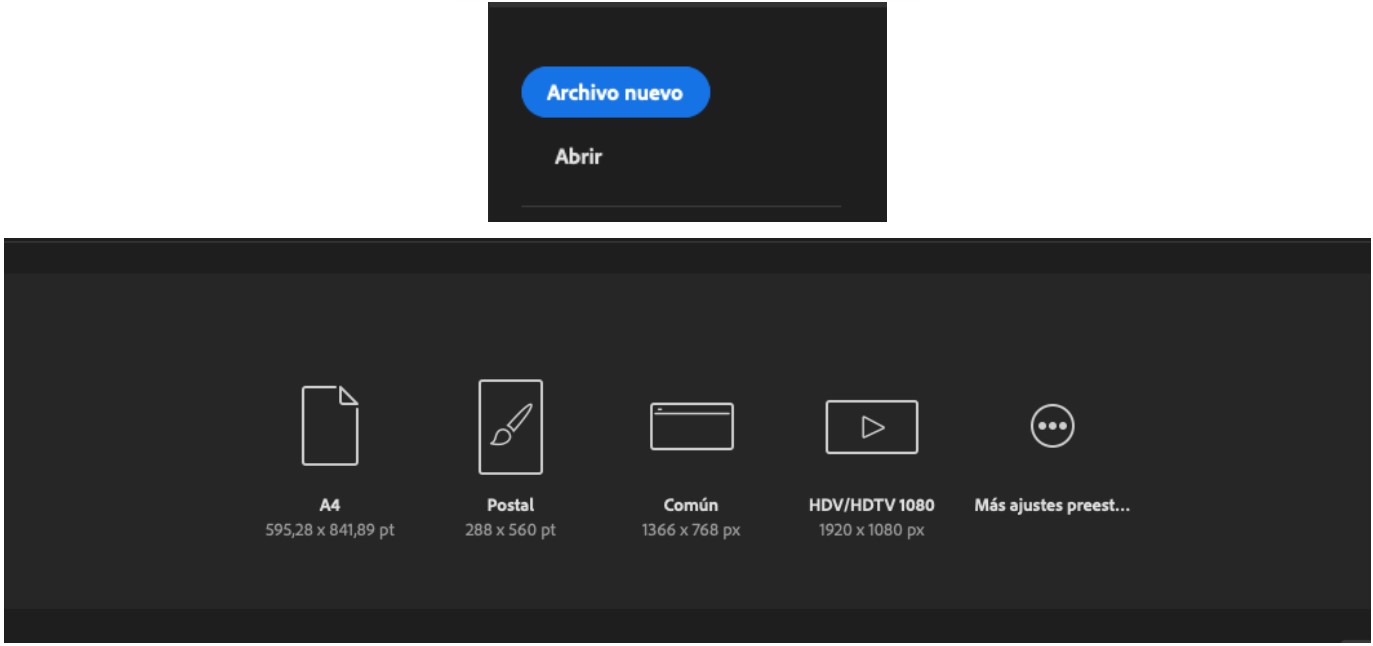
Open Illustrator and select New File. Choose the canvas size you want to work with; in this case, I selected an A4 size, which I can redesign and adjust to a size that suits my needs once I finish.(Fig. 7).
Fig. 7. New file
Step 2: Drawing your sketch
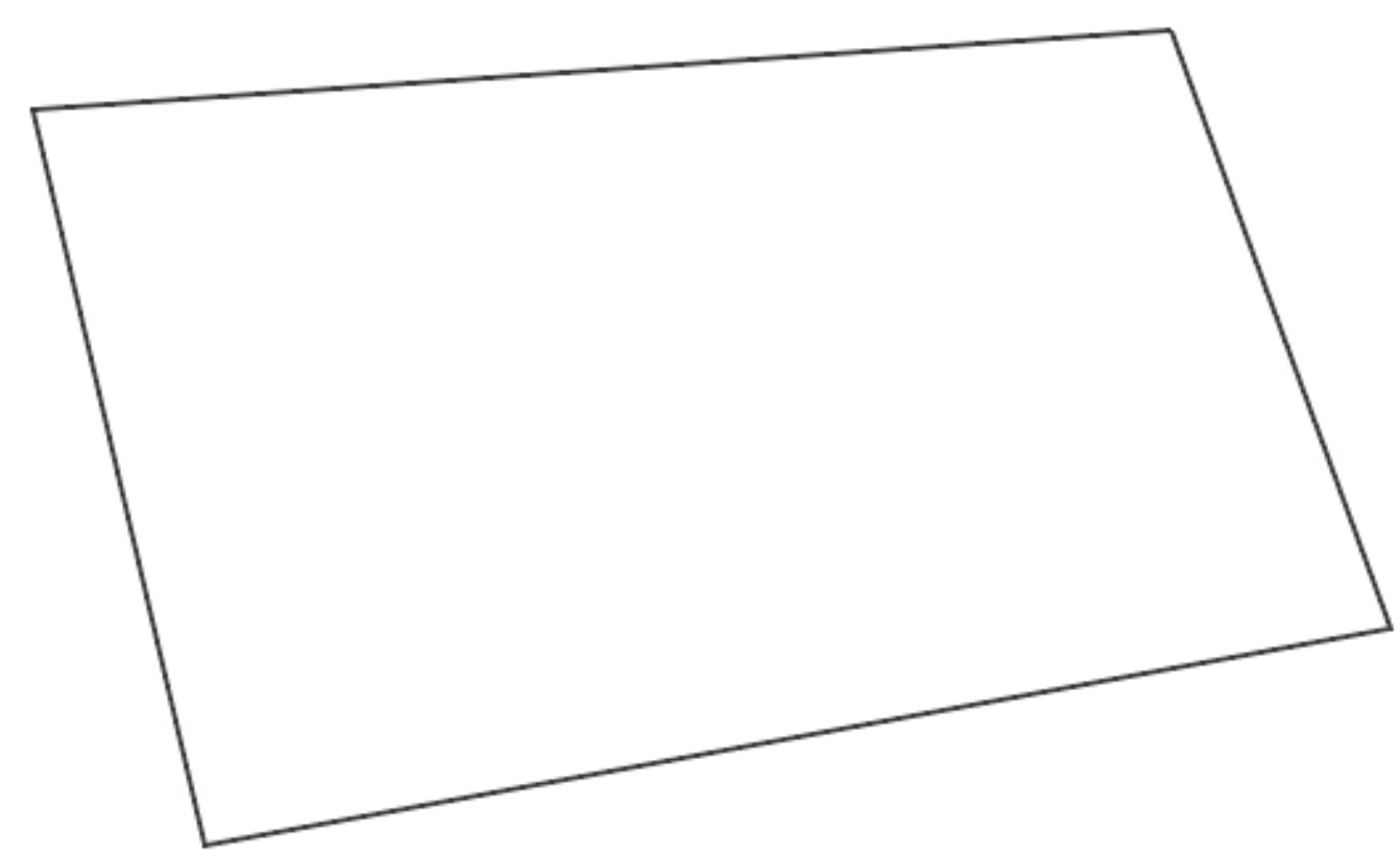
Select the tool that suits you best; in this case, I chose the Pen tool (P) as it provides more precision in my strokes. The sketch I am creating is the isometric viewisometric view of my robot, so my first shape will be a parallelogram or inclined rectangle. (Fig. 8).
Fig. 8. New shape inclined rectangle
Step 3: Add the ramp
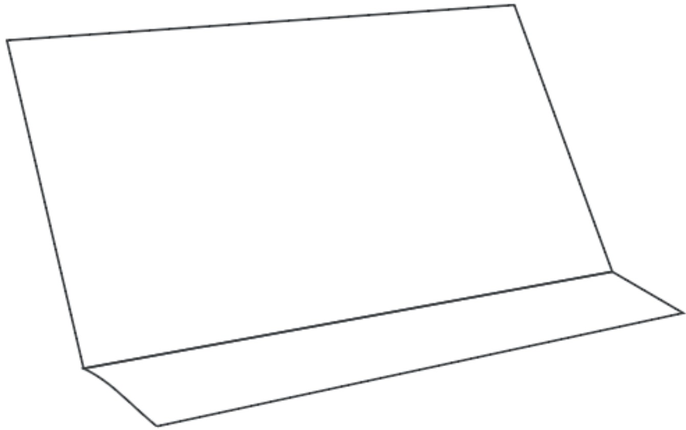
Add a rectangle with the same width but shorter in length, and slightly more inclined to simulate that it is a ramp. This is the front of your robot. (Fig. 9).
Fig. 9. Front of you robot.
Step 4: Complete the ramp
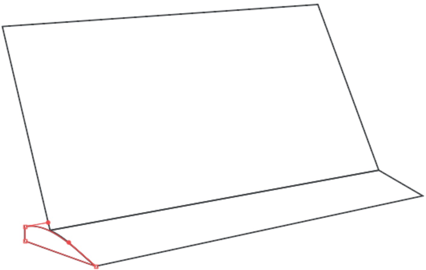
Draw a small arc on the bottom left side to complete the ramp.(Fig. 10).
Fig. 10. Complete de ramp - isometric view
Step 5: Cutout of the left side
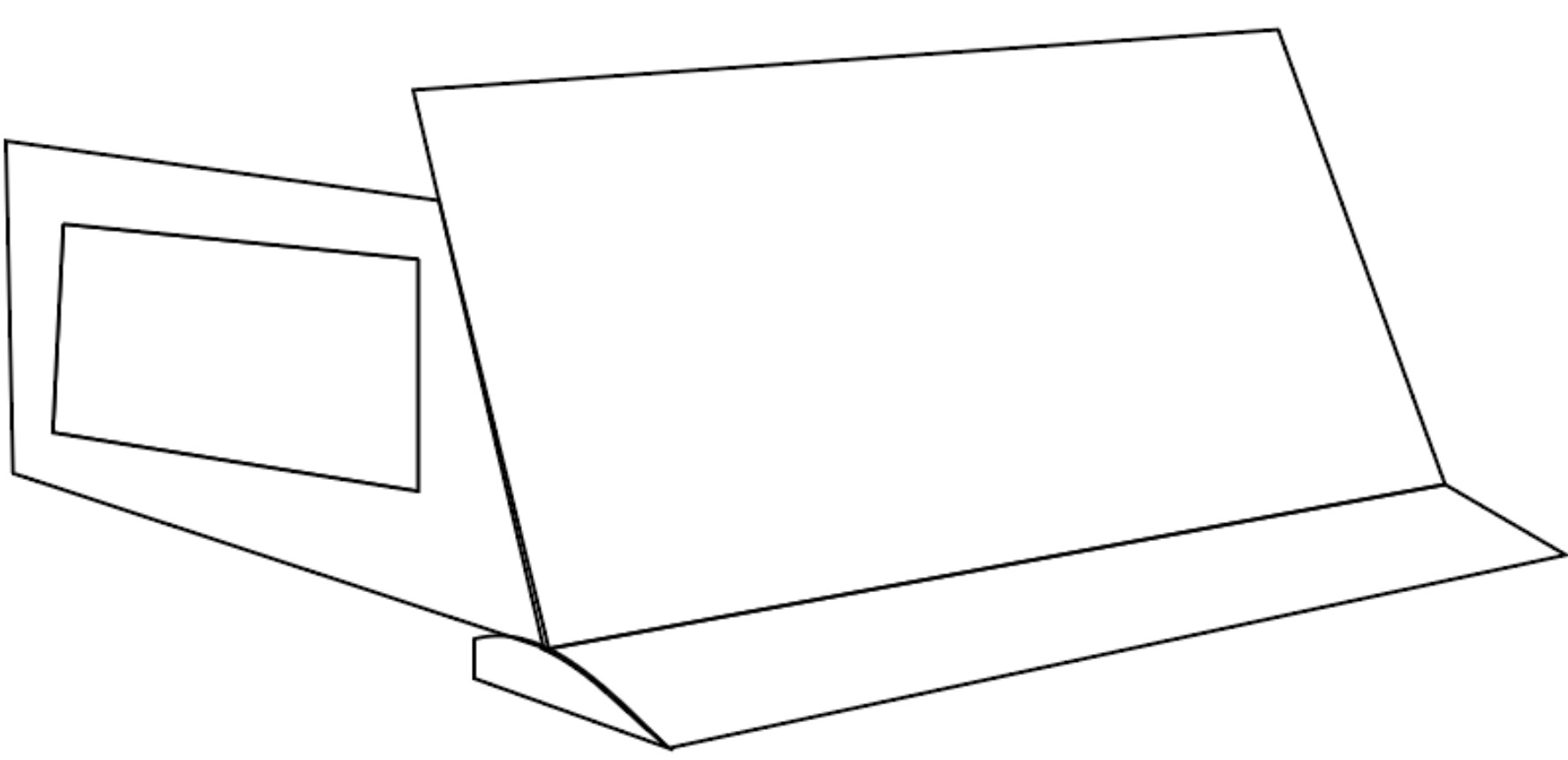
To create one of the side walls of the robot, draw a rectangle that respects the frontal shape of it. Inside this rectangle, draw a smaller rectangle that will later function as a cutout to prevent the robot from weighing too much.(Fig. 11).
Fig. 11. Cutout to reduce the weight of the robot.
Step 6: Rear side
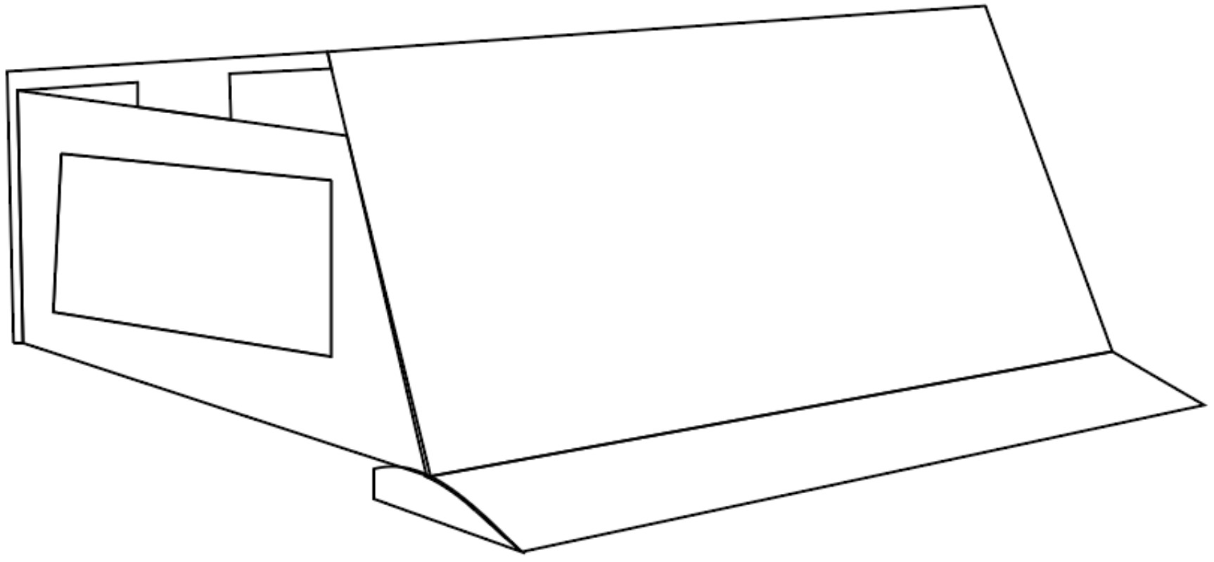
Add the rear side of the robot, leaving some spaces that will serve as cutouts again to prevent the robot from being too heavy and to allow for easier movement.(Fig. 12).
Fig. 12. Left side of the robot.
Step 7: Wheels
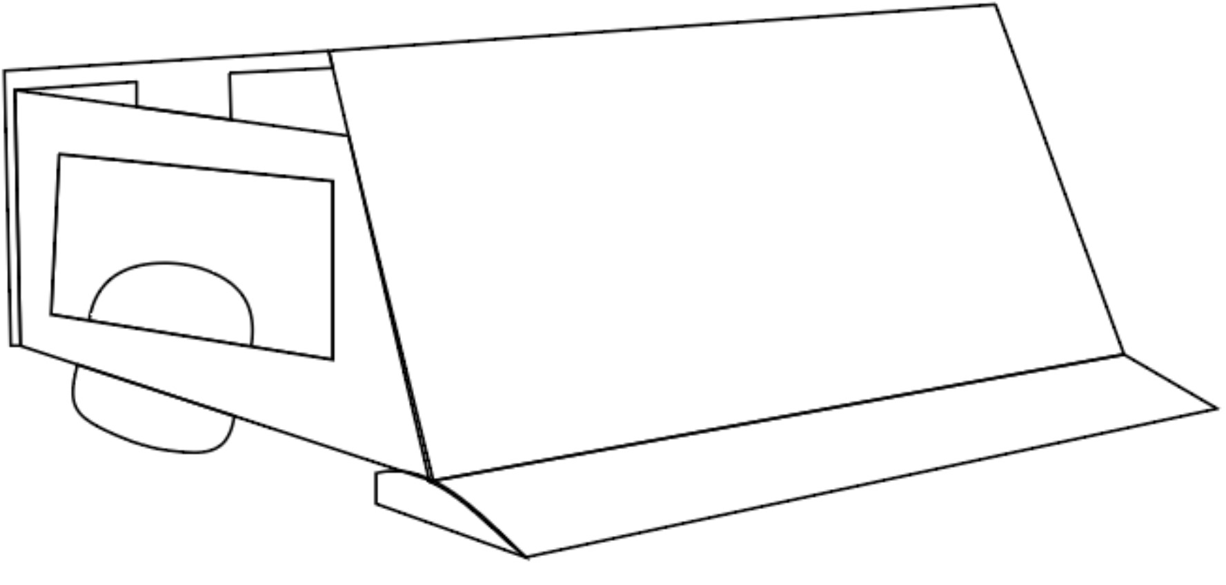
Add a circle that protrudes from the side cutout and also from the bottom left side. This will be one of the wheels of our robot.(Fig. 13).
Fig. 13. Wheels of the robot in isometric view
Step 8: Color
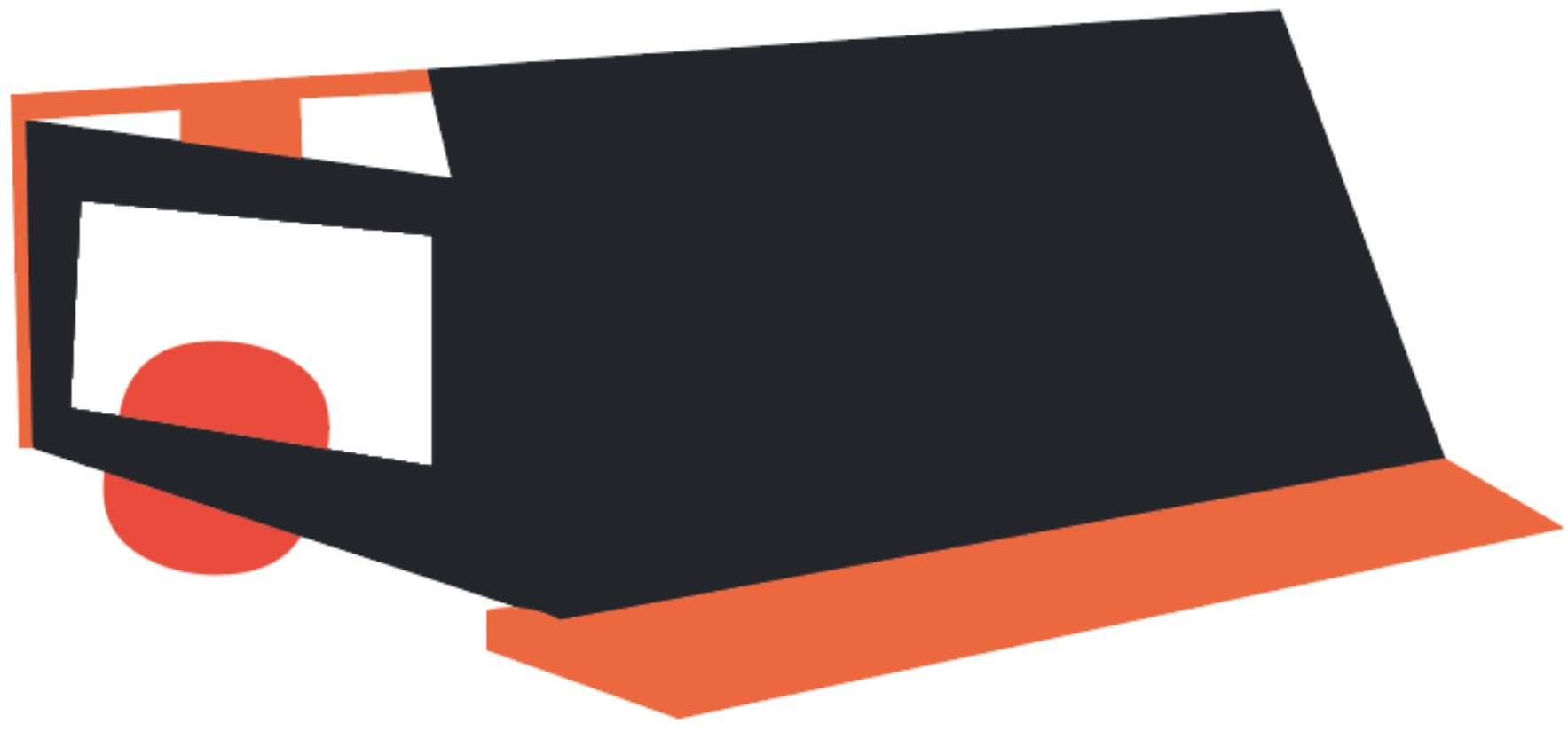
Add color to our sketch; it can be any color. I preferred to use a gray color for the metallic parts and highlight additional elements such as the ramp and wheels in orange to make them stand out.Fig. 14).
Fig. 14. Robot in isometric view.
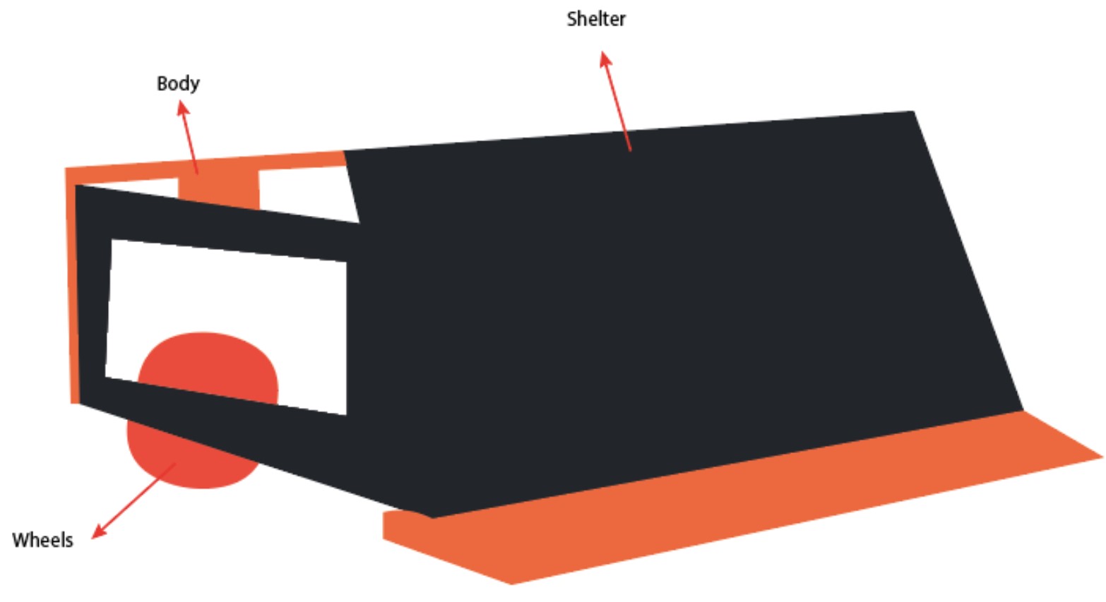
Step 9: Final sketch
In this image, we can appreciate our 2D design of the robot, with markings indicating the components in an isometric view.(Fig. 15).
Fig. 15. Markings indicating
Conclusion
2D design tools are very useful for image editing or prototype design. GoodNotes is a basic tool that allows us to create vectors and drawings in a simple and straightforward way. However, it does not have the wide range of editing tools that Illustrator offers. Therefore, for future 2D designs, I will be using Illustrator.
