4. Electronic production
Group assignment
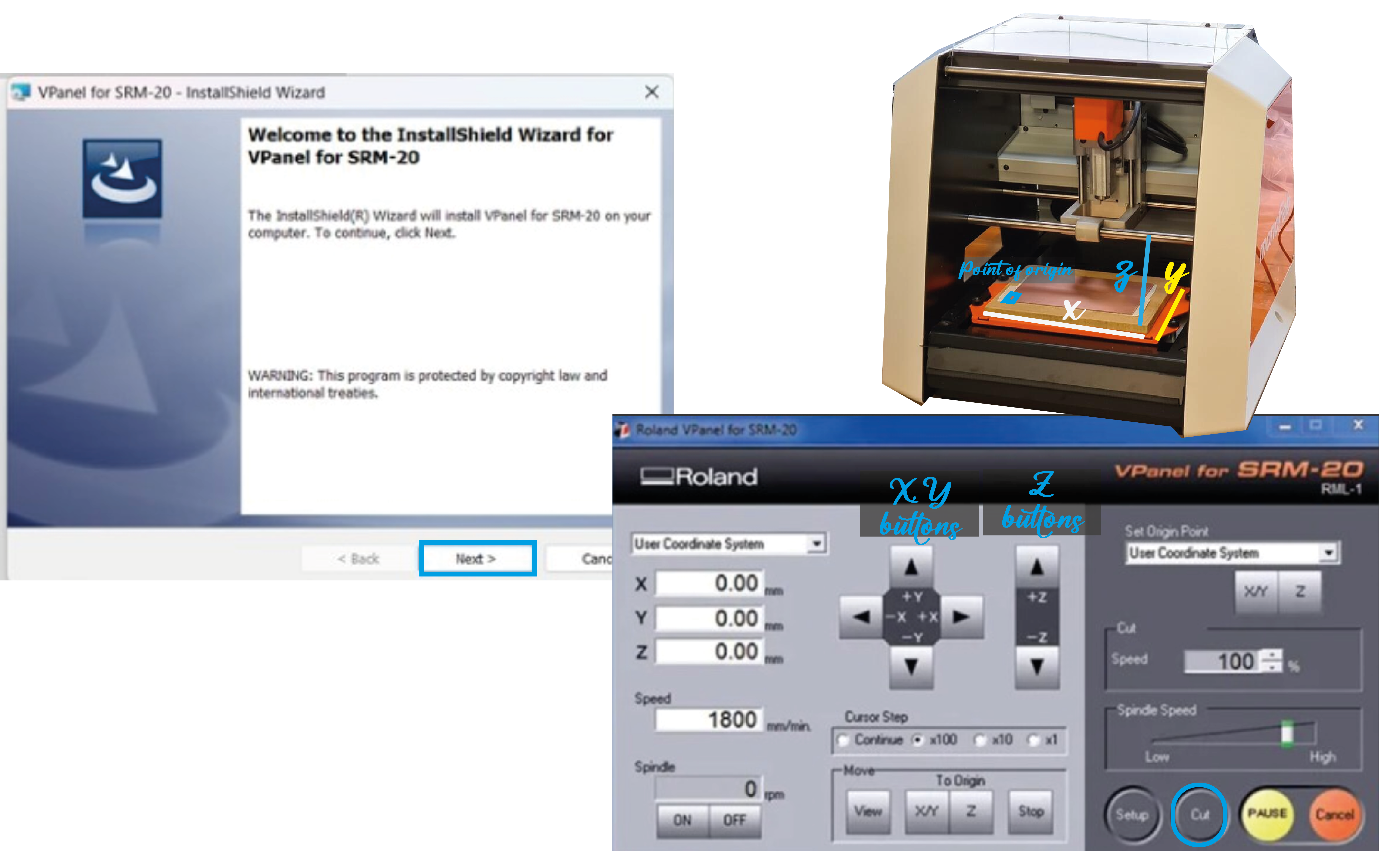
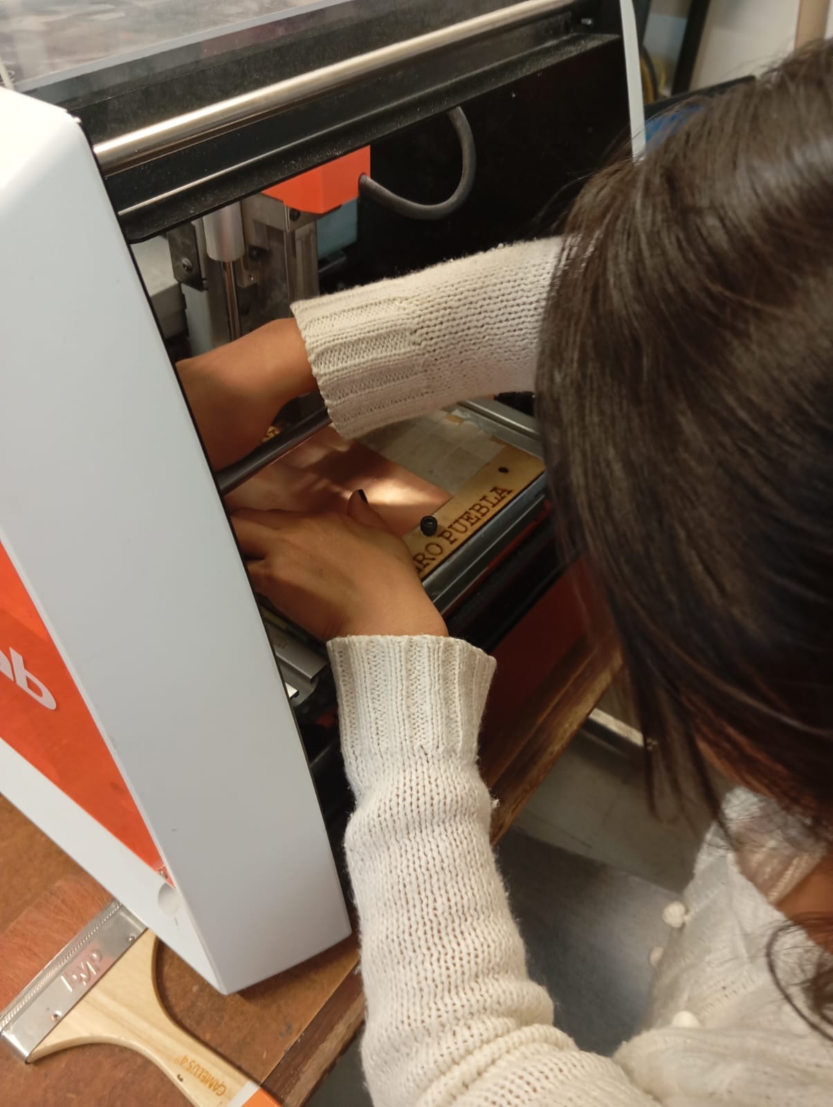
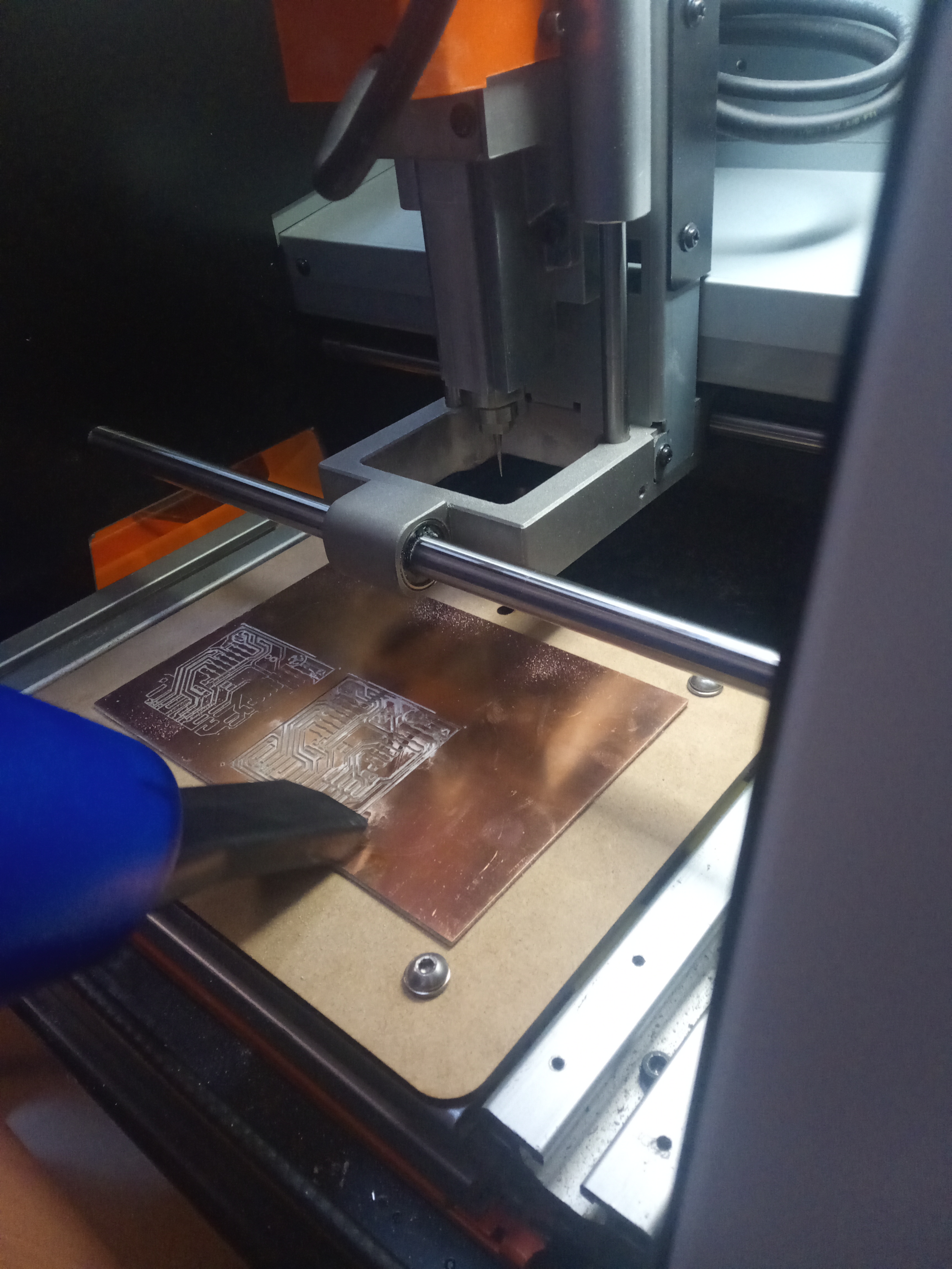
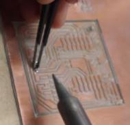
This week we worked on the design of a circuit. To cut and engrave the plate, we use a MONOFAB SRM20 milling machine with two cutters, one for engraving and the other for cutting and drilling.Imagen de la fresadora.

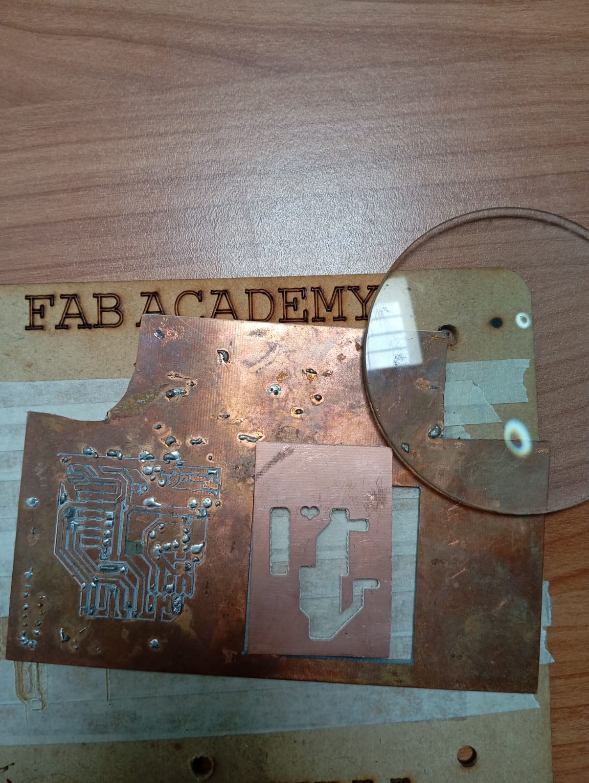
My first PCB
Like every CNC, it needs a program that links it, which is why we used VPANEL, which I found to be a fairly easy program to work with and easy to understand, designed with touch buttons to regulate the feed speed, spindle speed and milling in x, y, z axes, which help us to position the milling machine.
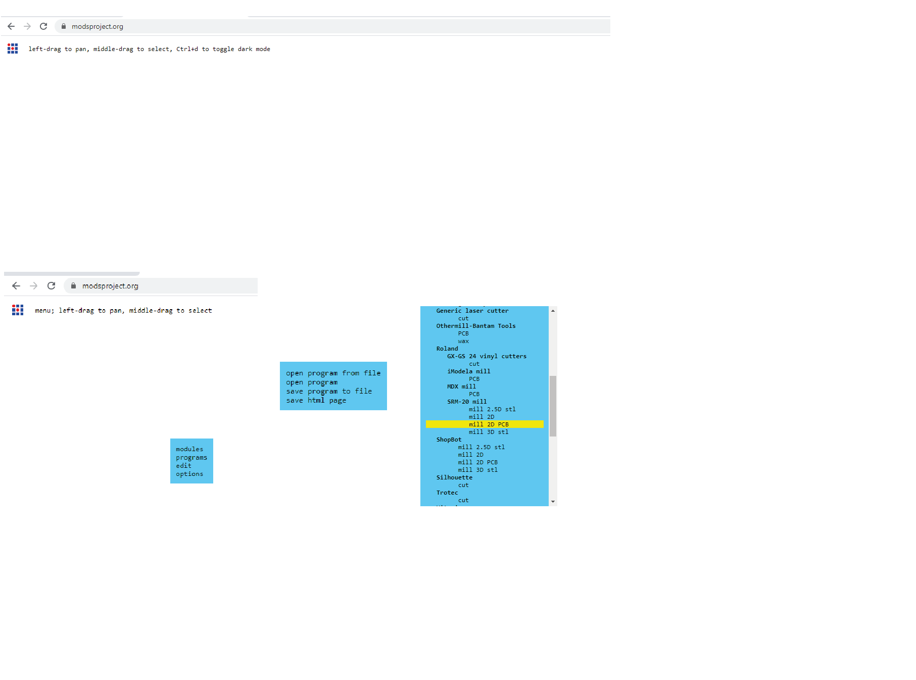
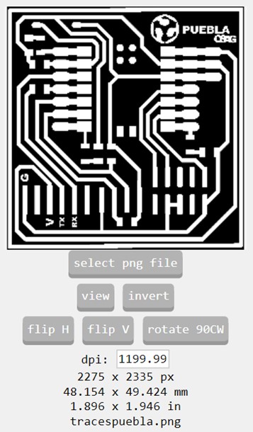
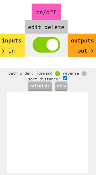
To prepare the cut we use MODS CE, here we determine the plotter, the number of passes our plate will have, we also define the cutting and engraving files, that is, we configure our file.
For that, we must put CE mods in the search engine, here I leave the Link to locate it quickly.
Now on this site, by clicking the right button we can open the program in the window that opens in the “program” option. Once selected, a new window appears where we will click on “open program”, this in turn opens a new window where we will choose the tool we will use, in our case we select “Roland SMR-20 mill 2D PCB”.
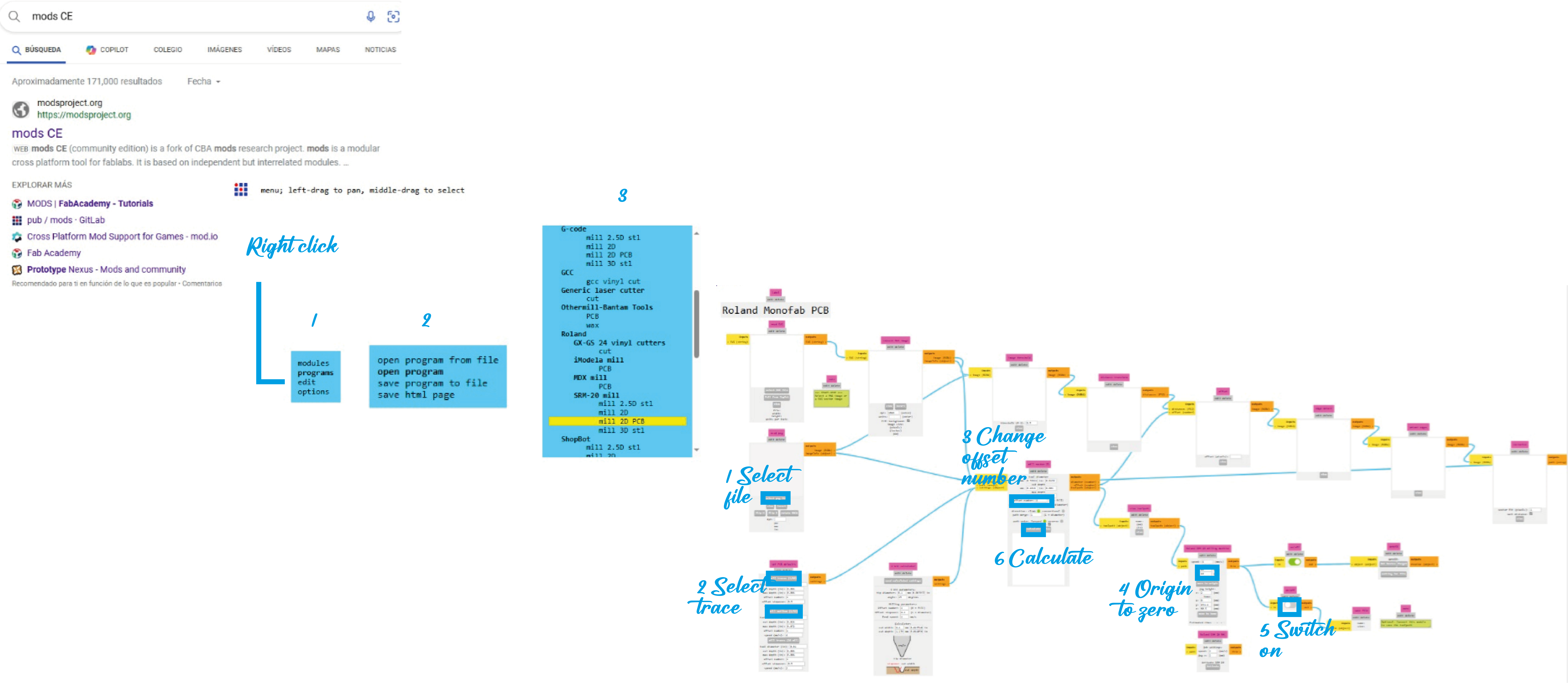
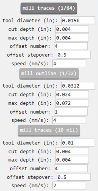
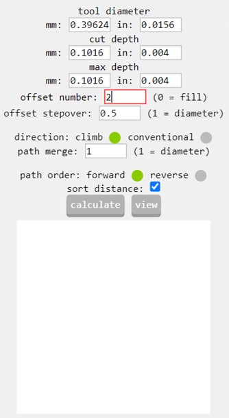
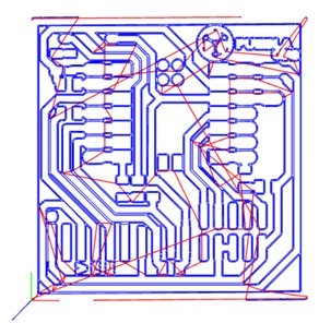
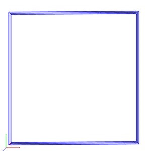
In the previous image we unified the process, but to avoid errors I describe below what should be done: In the mods project, select the PNG with the first cut, which shows the design. The same process is used with the png outline, but selecting the "Invert" option so that the image colors change and the program recognizes the correct cut. To burn the card, select the "mill traces (1/64)" option, which already has a certain setting. I changed the "offset number" to 2 for recording.
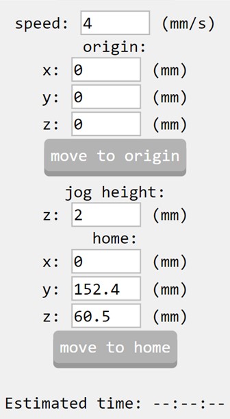
I changed all the source values to zero, turned on the output to download the files automatically and immediately the path it will follow is shown.
By messing up you learn *u*
Let's do it
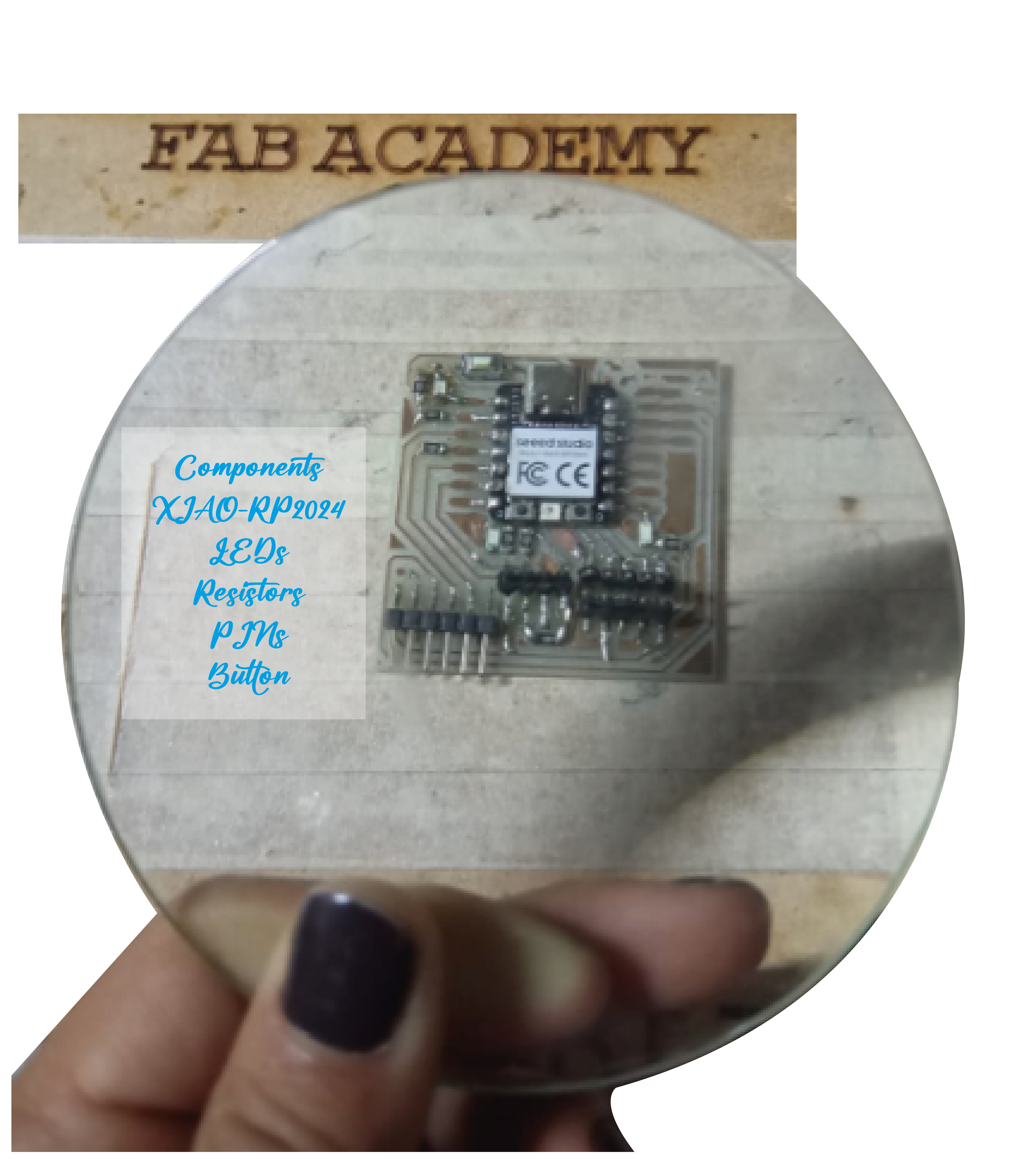
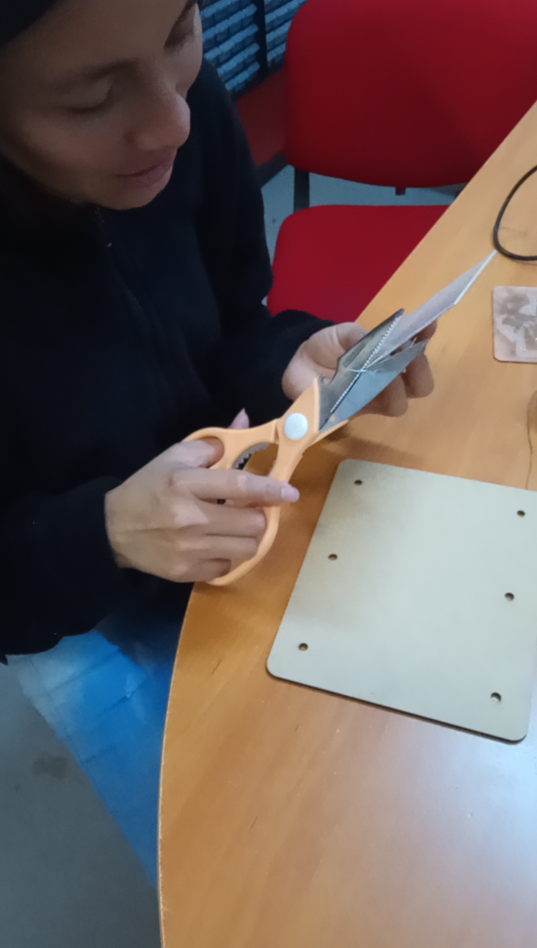
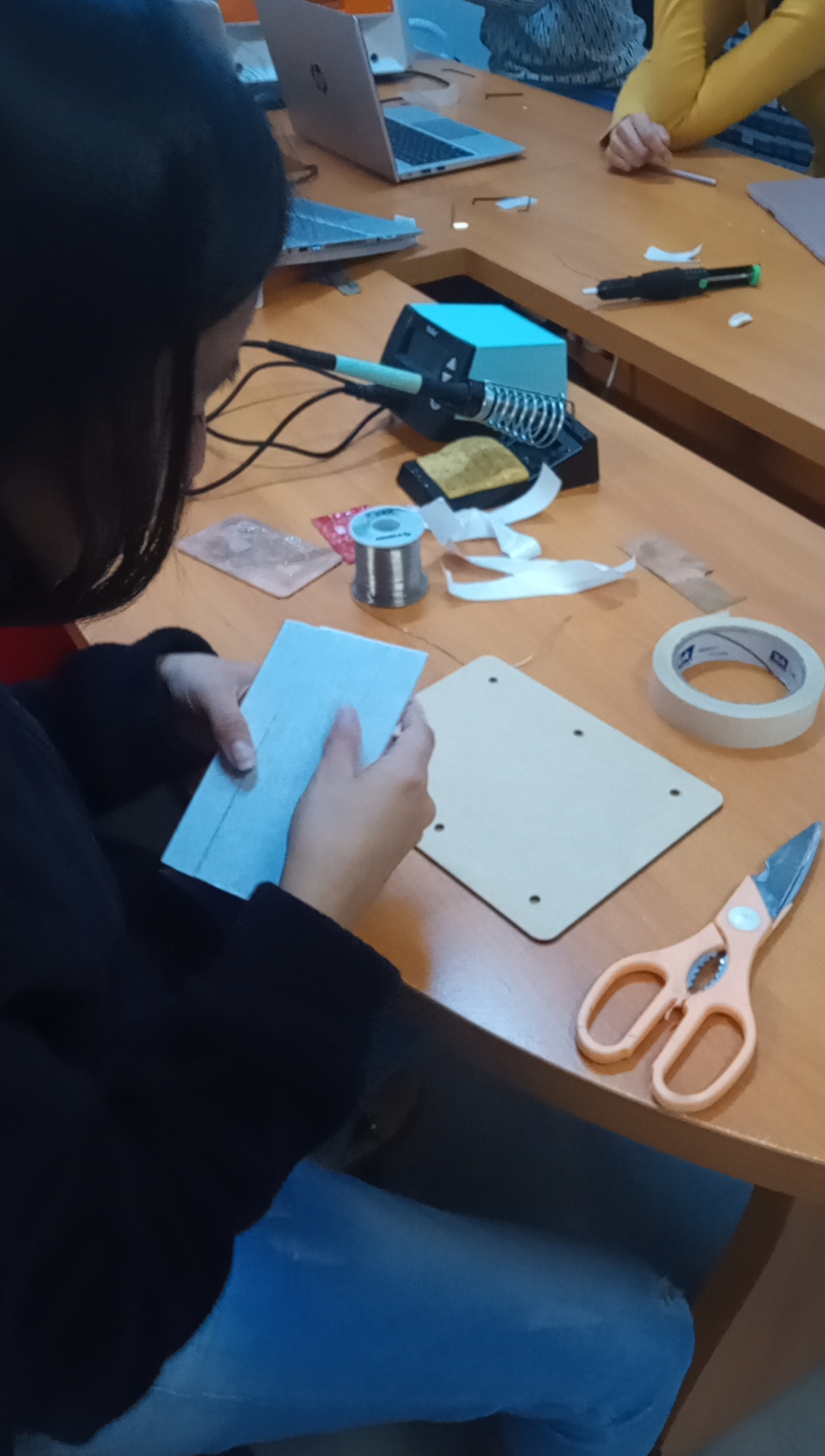
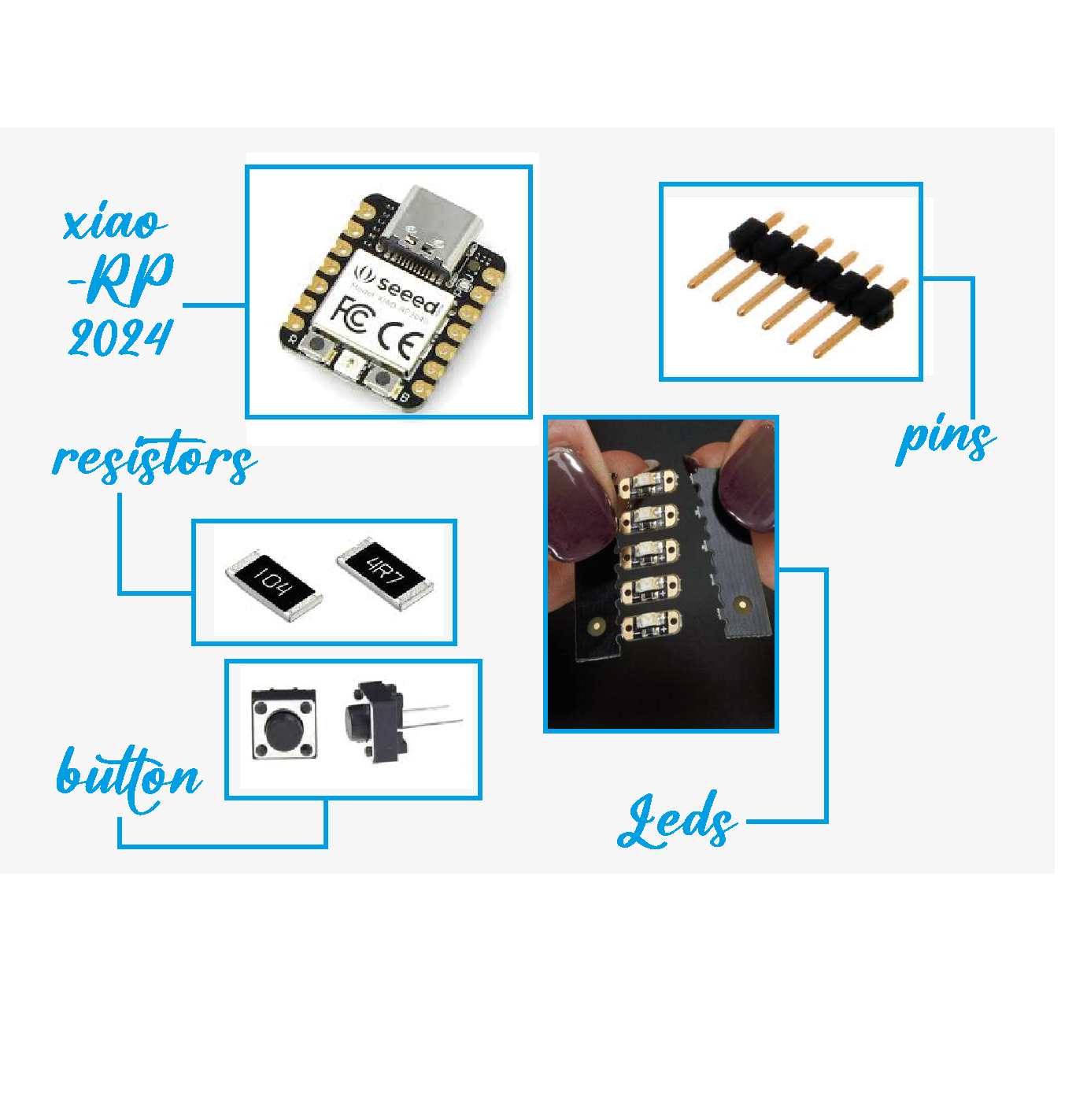
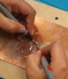
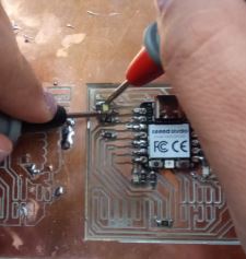
Once we have the pcb cut and engraved, we have to place the elements that I still don't know exactly what they are for, but they gave us to familiarize ourselves with the components and their function, in this case we used:
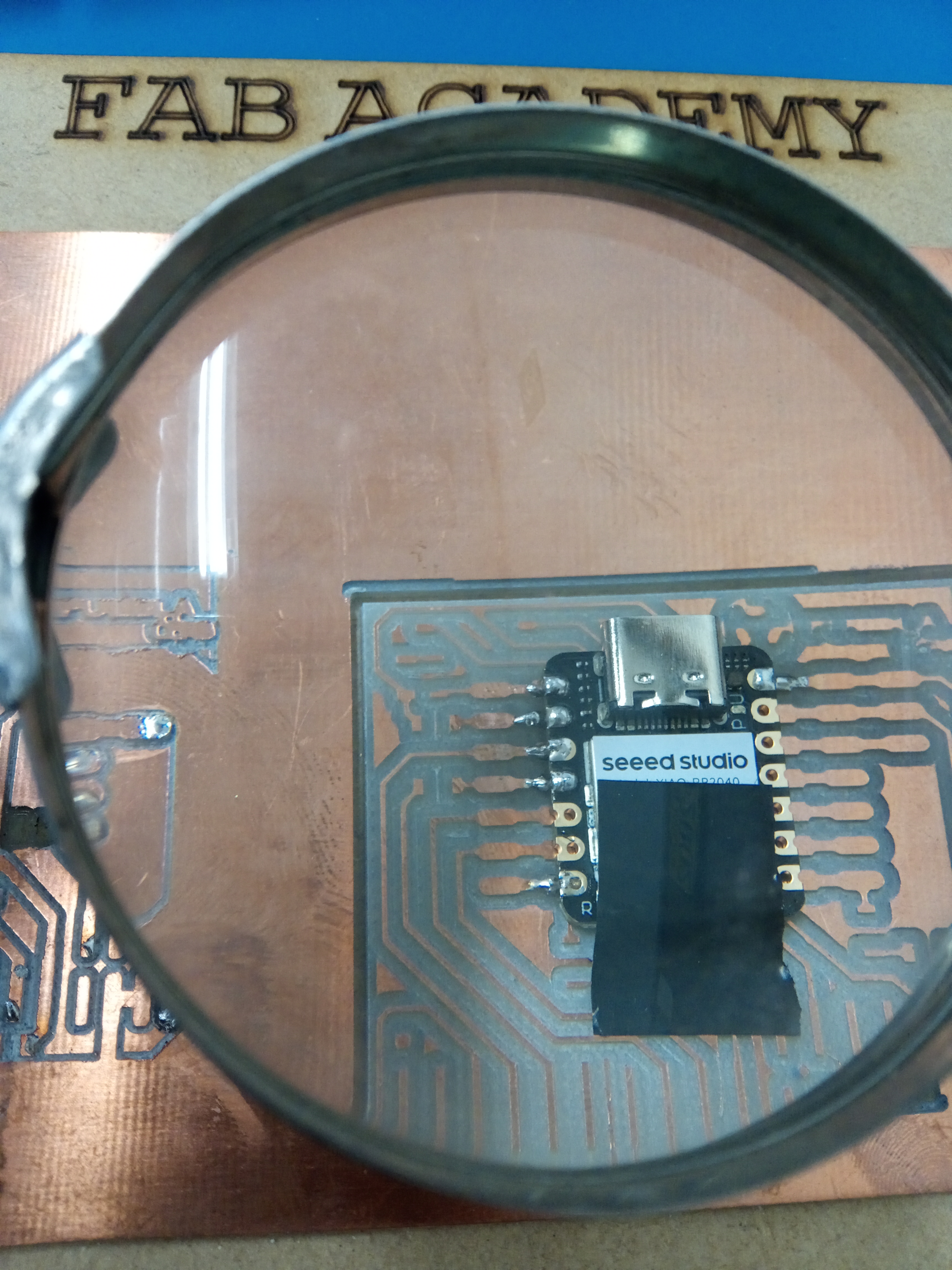
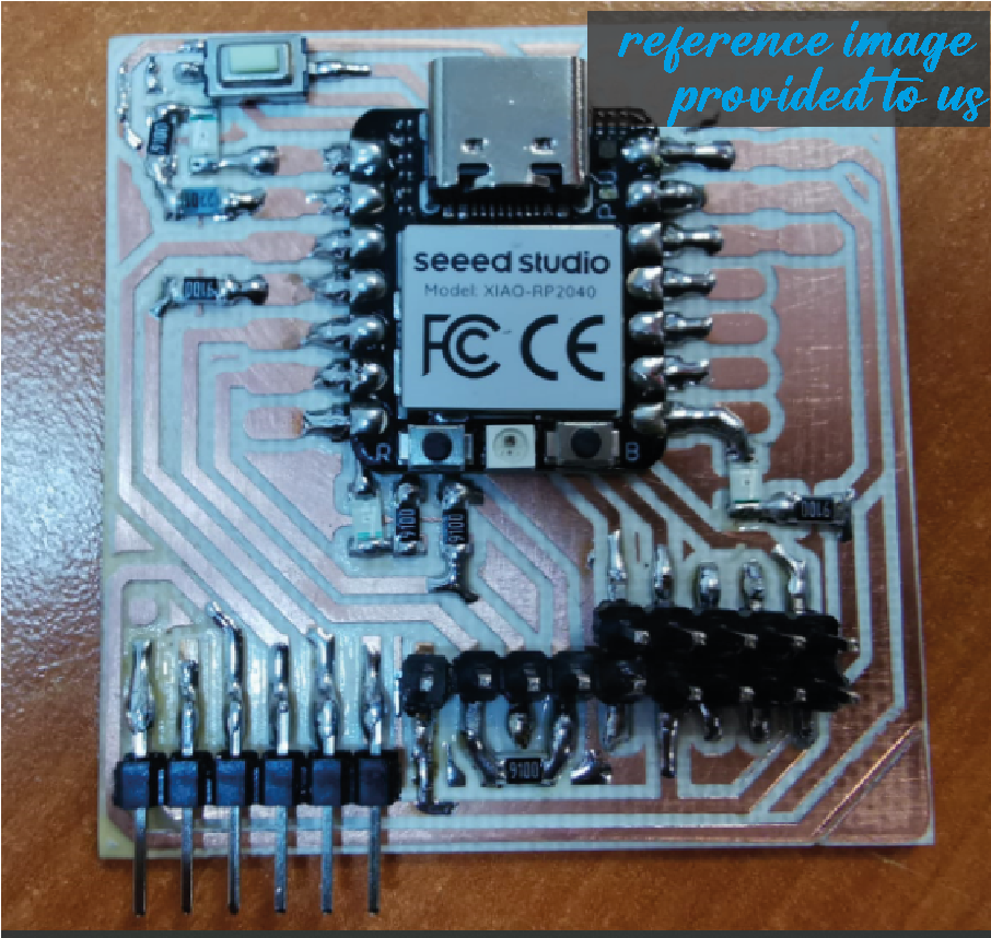
With the reference images and knowing where the components should be placed, we begin the task of soldering our circuits.
Final score