2. 2D & 3D DESIGN
This week we worked with two new 3D design programs for me, but not only that, but they also gave us options to work on 2D design, which I found interesting since I'm getting out of my comfort zone.
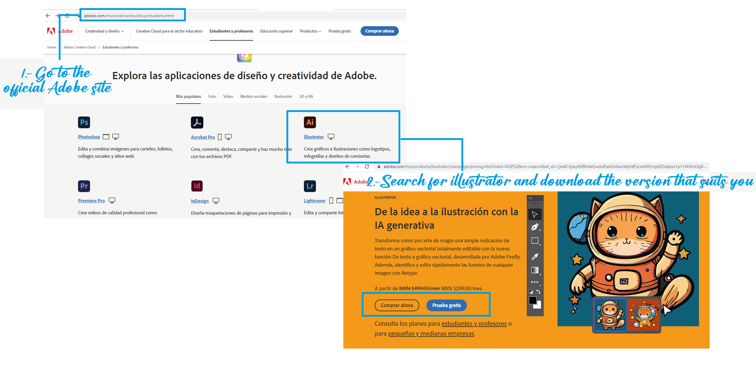
I usually use Illustrator, although I only have the student version, I really like it since it is very friendly and intuitive, plus there is a wide variety of support videos to do any work related to design.
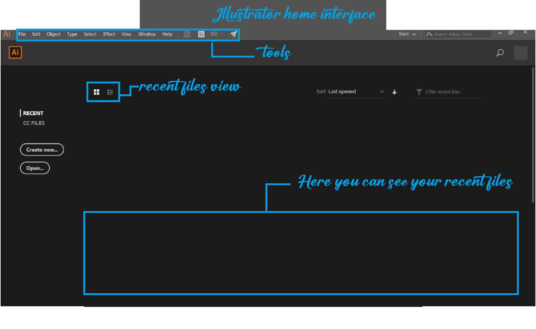
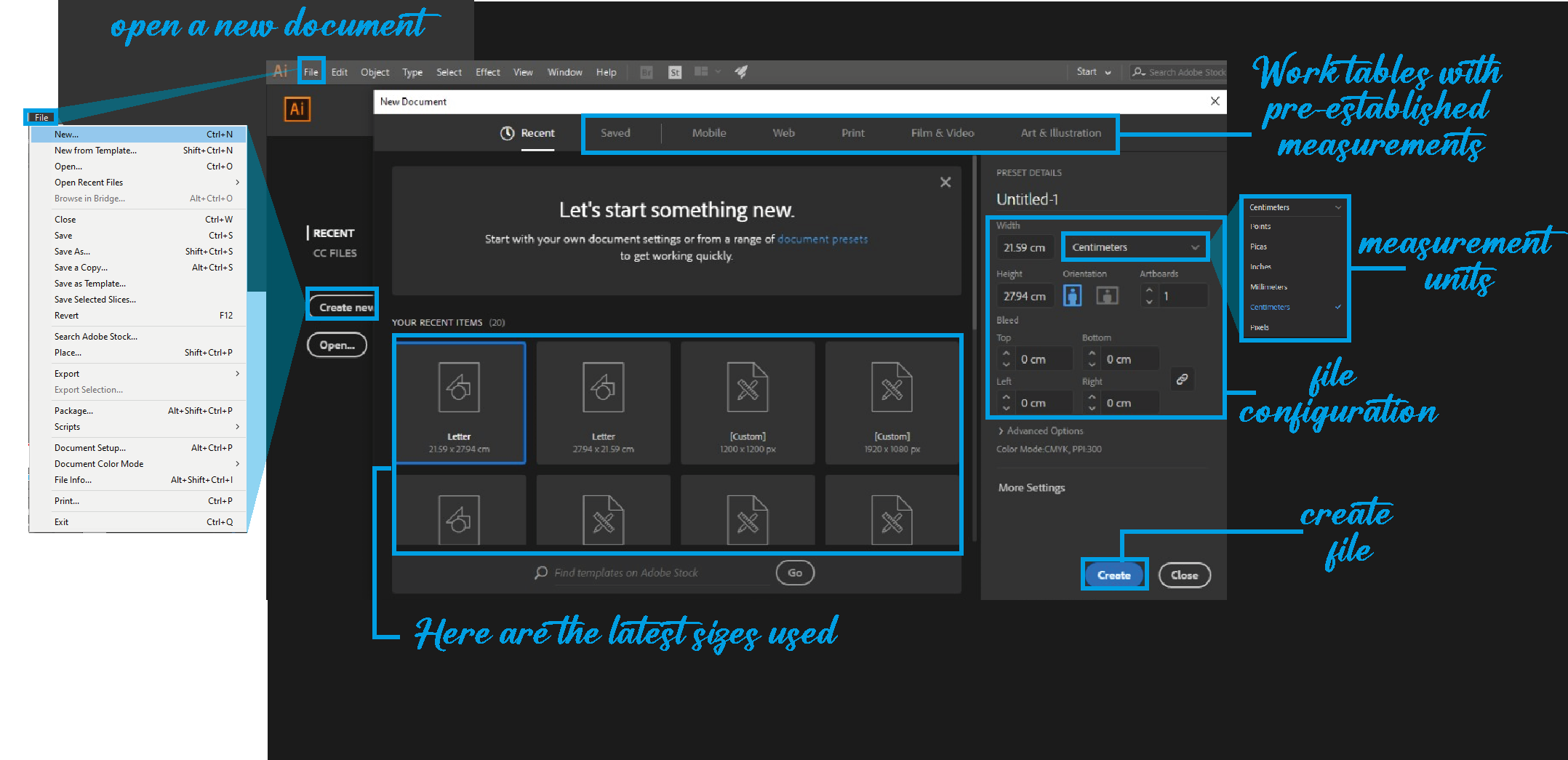
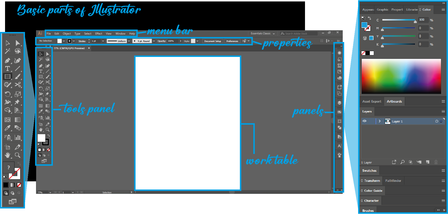
Next, I present a little bit of the Illustrator interface that I like so much.
Learning 2D again
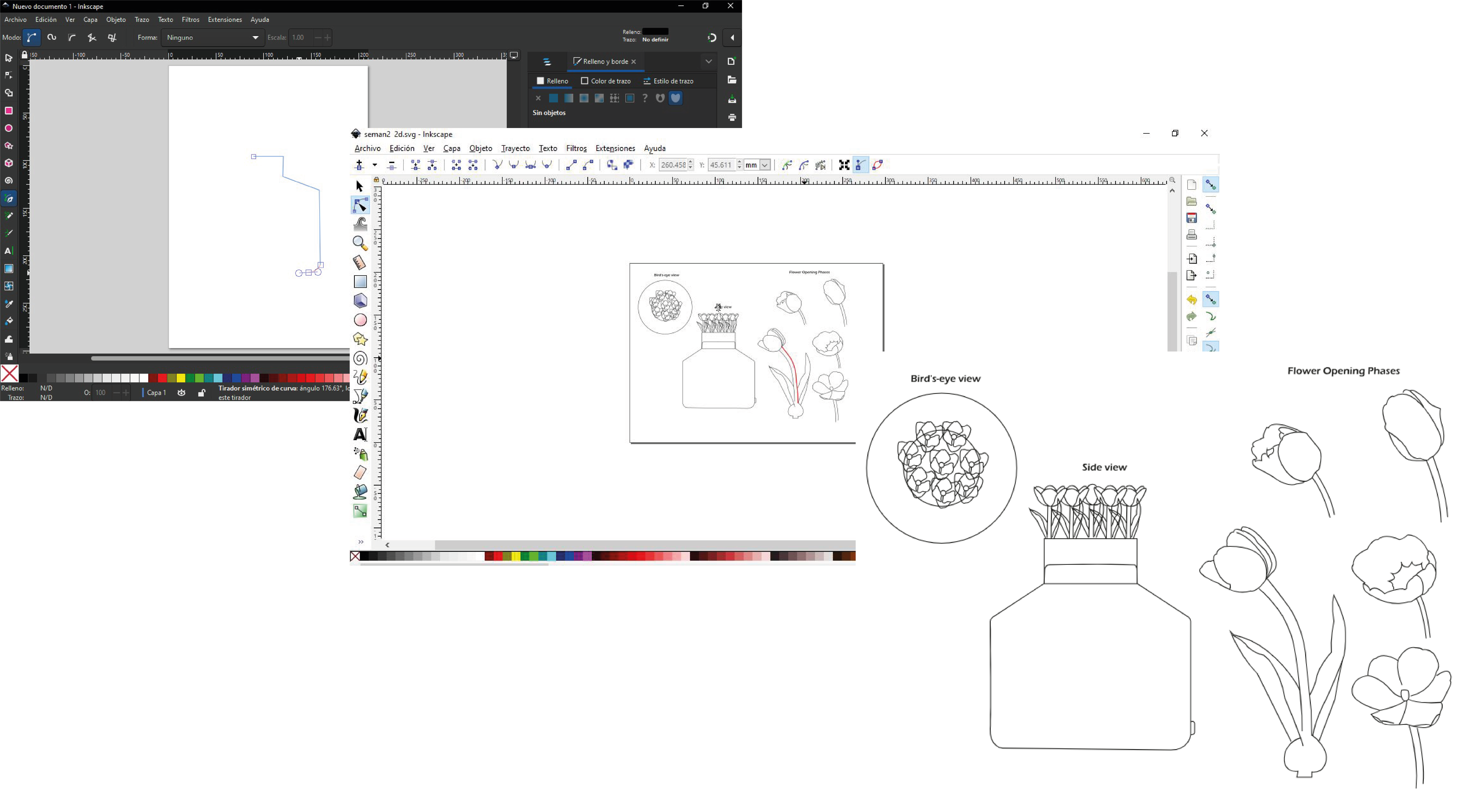
For the activity, in the 2D area I made the sketch of my project in clean, contemplating basic parts, a sketch not very detailed that will help me to consider changes and new elements.
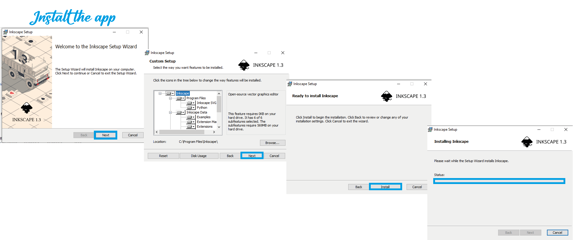
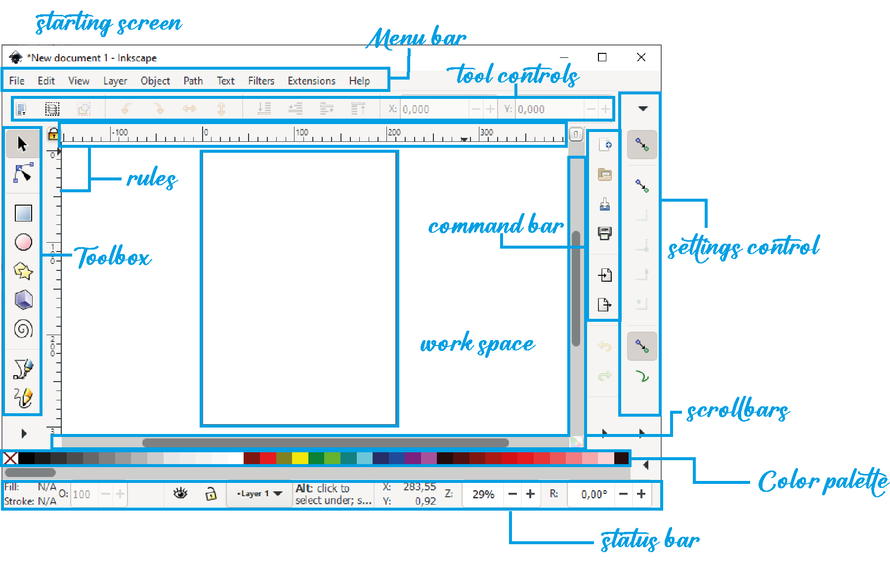
This sketch was made in Inkscape, which you download for free online, it is a program that allows us to create graphic objects for which it includes different tools for drawing, shape, text, even allows us to embed images that can be treated in the program, as well as has a tool to create patterns and use clones. This program is quite friendly and intuitive, it looks a lot like Illustrator, you can create from scratch or import works to complement your work.
In the following images I give you a quick tour of my process.

In this case I did it with the pen tool, it is a sketch of how I imagine the final product, contemplating the parts and some materials, in addition to the position and assembly of each one, like any file, the first thing to do is open a new document and later you start drawing, you can rely on your scanned sketch or simply start from geometric shapes.
Introduction to 3D
In the case of 3D design, the first one I downloaded was Solid Works, I read the installation manual, downloaded it, installed it and started doing some exercises to get to know it and see how the tools work.
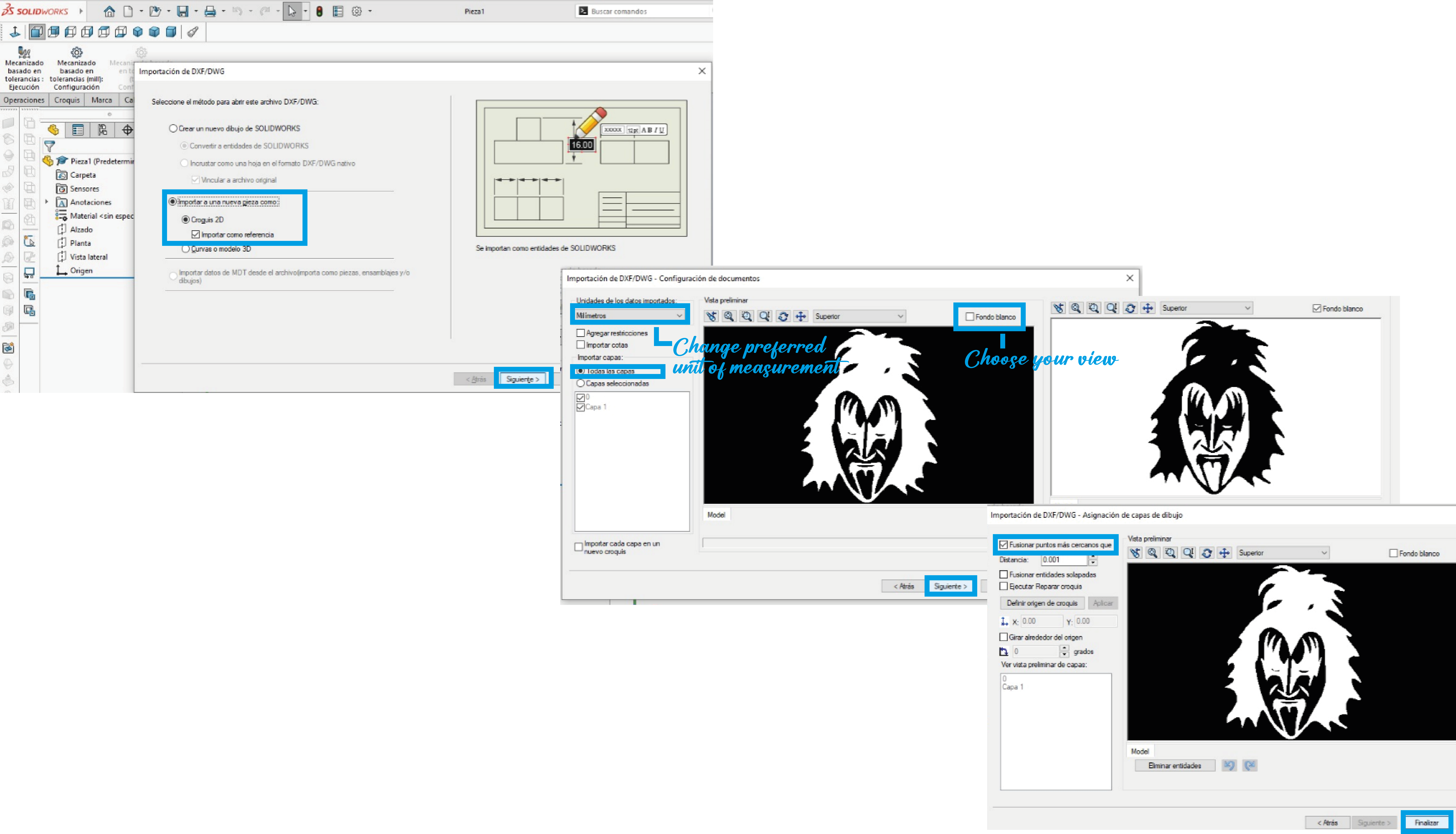
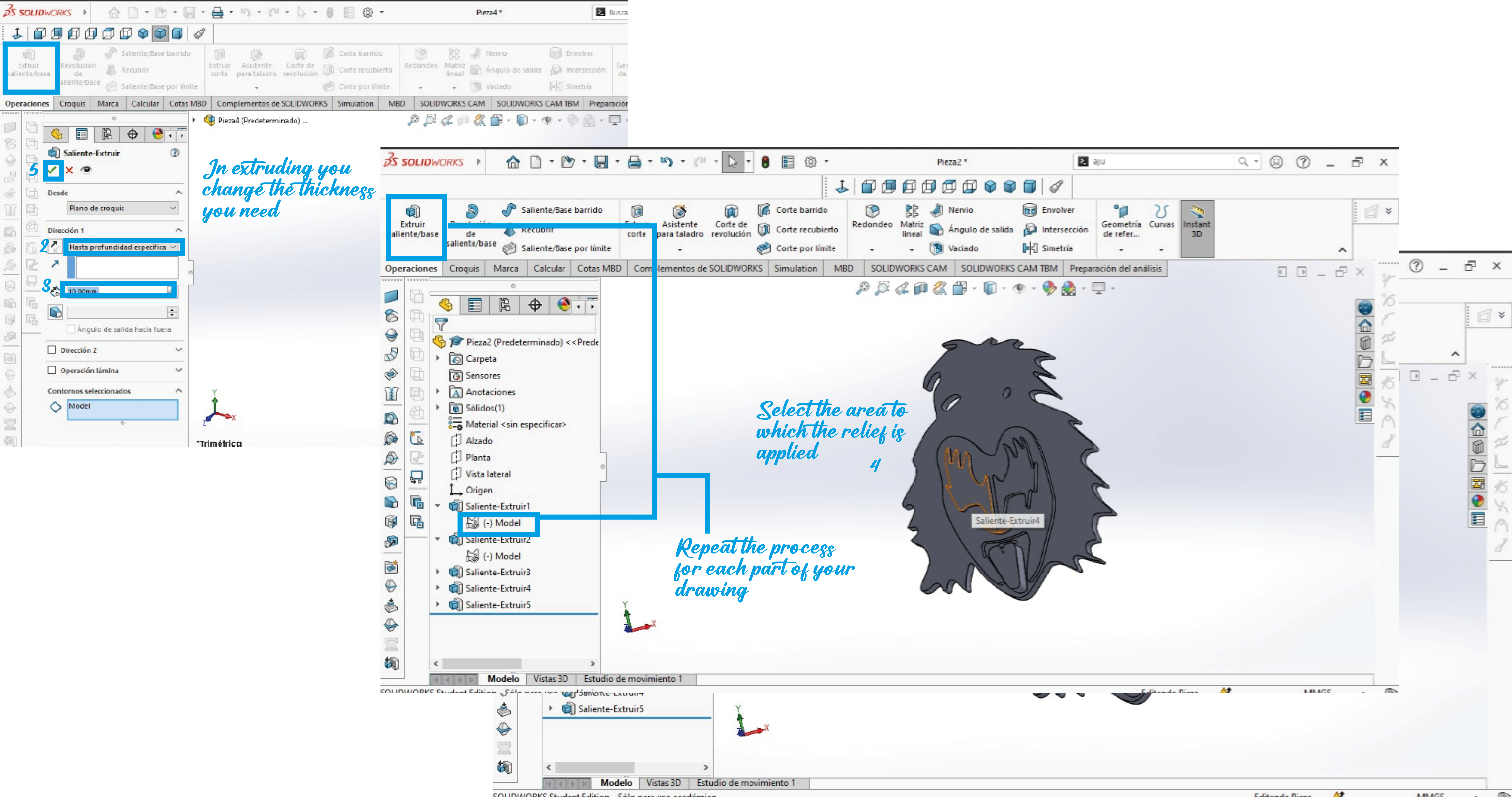
The first thing I learned was to do a quick vectorization and give it relief, this project can help me create basic pieces from a drawing, which opens in Solid in DXF format, once opened we begin to use the extrude tool and We easily begin to thicken the image in order to convert it to 3D.
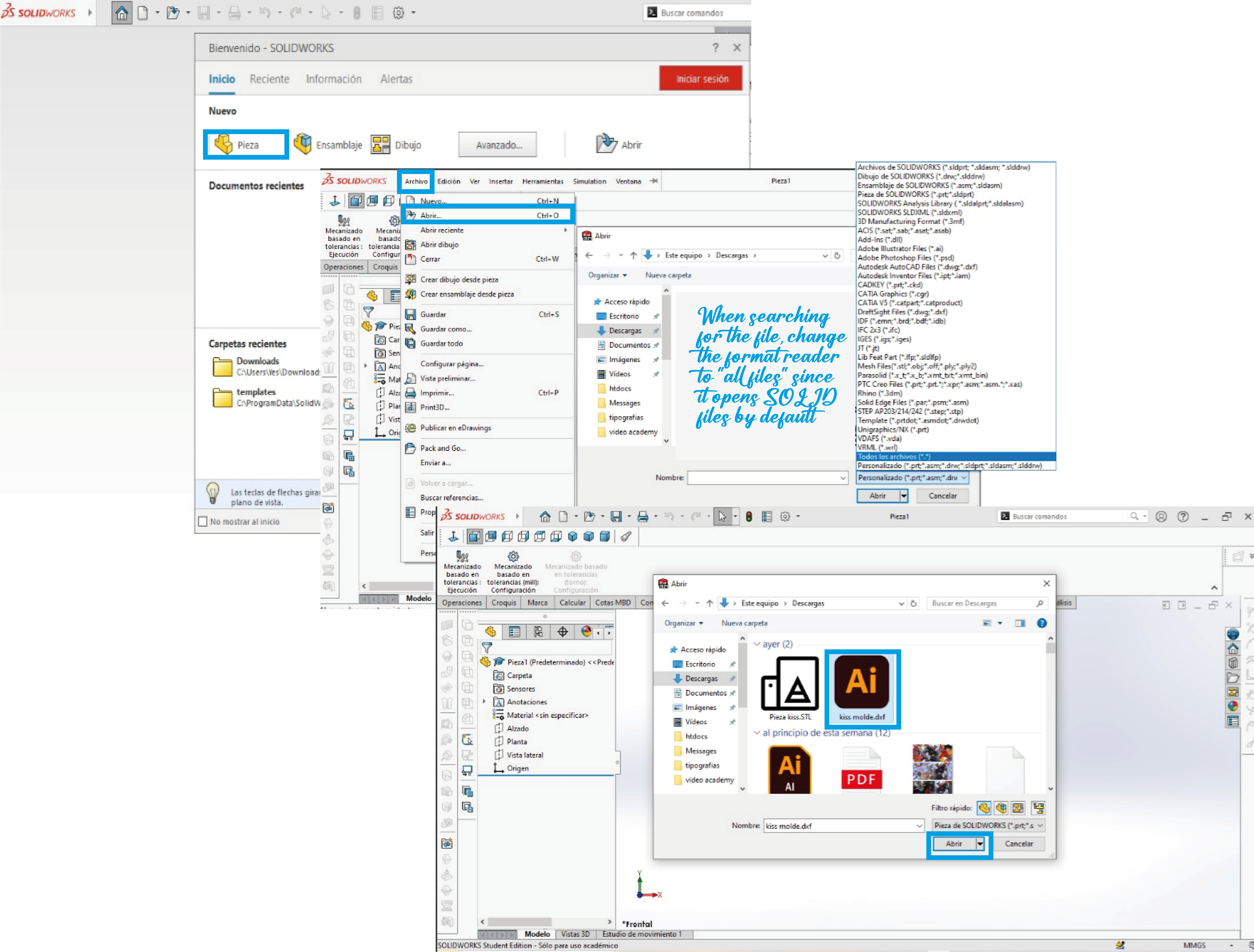
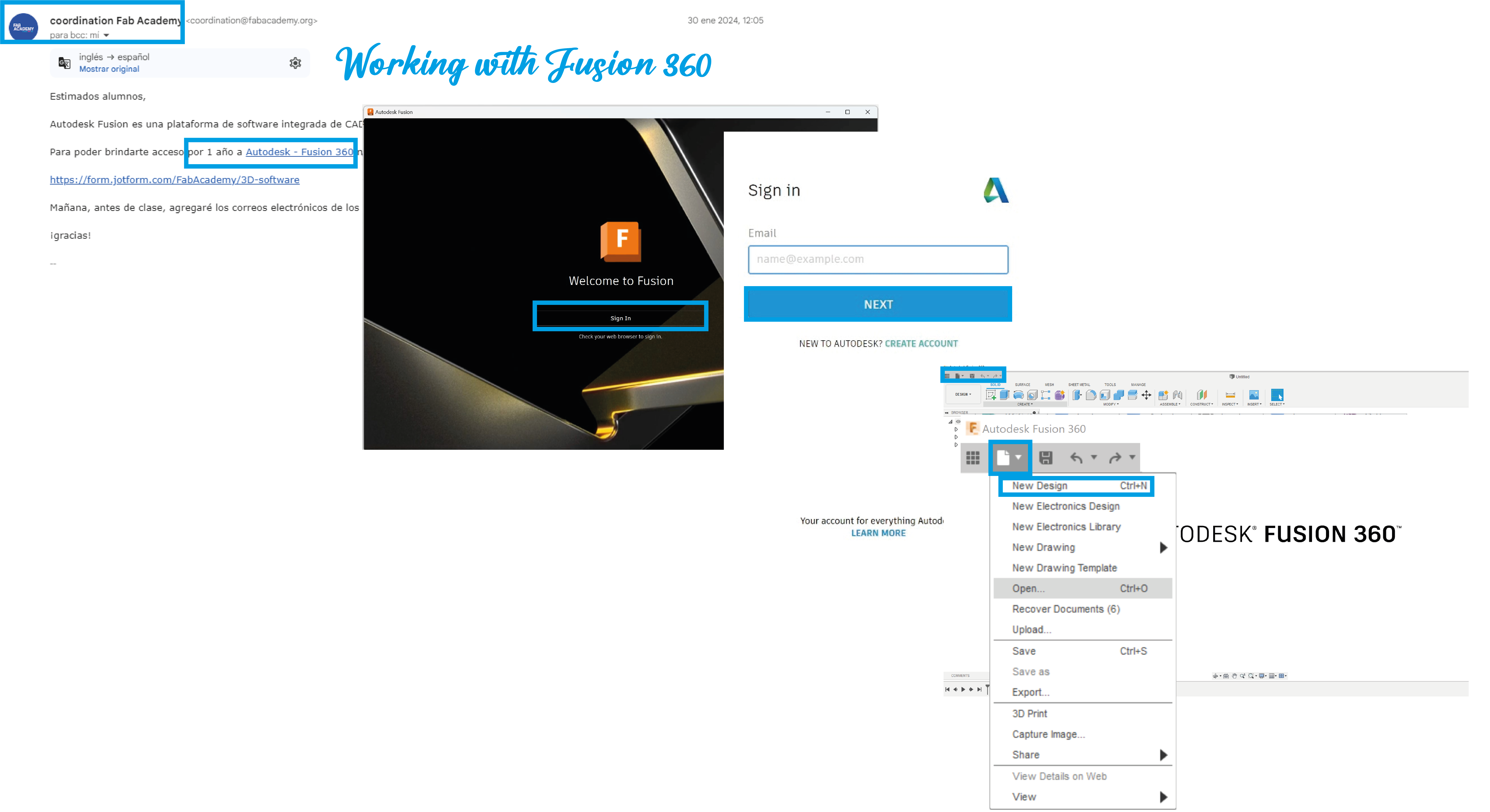
Later I registered to use the fusion 360 program, I didn't know this program either, but I liked it, it is somewhat related to Solid, both are very good for working with exact measurements and ensuring that our pieces have the least possible error.
Autodesk Fusion 360 is a cloud-based 3D modeling CAD, CAM, CAE and printed circuit board software platform for product design and manufacturing, you only need to register in a form to get access for 1 year thanks to the academy.
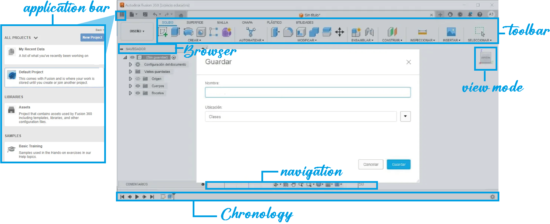
Our local advisor gave us a virtual session on how to work with fusion and we made a piece to order filament, following the steps that he indicated to us.
The first thing was to open the document, go to Modify > Change parameters. In the parameters table, select "+ User Parameter" we gave a name, units and expression. In the parameter table, we write the data that the advisor recommended, establishing minimum and maximum diameter parameters.
We draw the part and then use the extrusion tool to give volume to our part and a window automatically appears in which the operation can be modified.
With the shell tool we eliminate the center of the solid piece, in the same way this tool helps us edit the thickness of the sides of our piece.
We drew a shape on the bottom of the part and extruded it to the edge since this adjustment was needed to place a screw, which is why a hole is also placed, to make the hole, we used the same extrusion tool. The "Cut" option is selected in the operations configuration panel. Here we can also modify the distance of the cut.
I add some screenshots of the work we do.

Our advisor tells us that the advantage of creating a 3D model with restrictions is that, when modifying the values, the model changes its proportions automatically, that is, we do not have to redraw it or create it from the beginning, just modify the measurements to try the same piece in different sizes or proportions.