
WEEK 4 EMBEDDED PROGRAMMING
1. INTEGRATED SYSTEMS
When we talk about an embedded system, we are referring to a device designed to perform specific tasks. These systems are adapted to applications that typically operate within a defined hardware and software environment. Embedded systems are currently a fundamental part of various sectors. Programming an embedded system involves developing the embedded software, which can be written in low-level programming languages.
CHARACTERISTICS
2. MICROCONTROLLERS
WHAT IS?
A microcontroller is a small computer designed to manage specific tasks and integrate processing, memory, and input/output peripherals, thus becoming independent and cost-effective units. This instrument works similarly to a computer, but is smaller in size.
RP2040
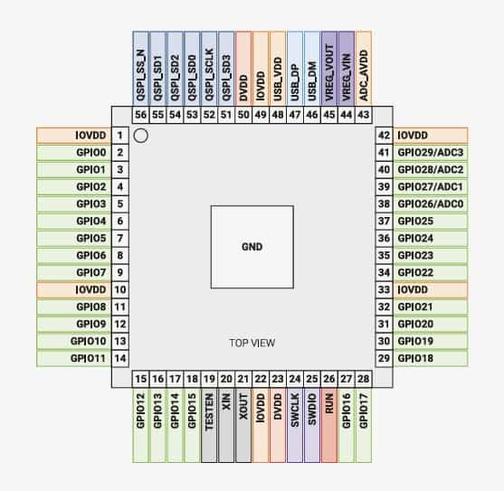
| SPECS |
| Dual Cortex M0+ processor cores, up to 133MHz (or 200MHz at 1.15V, see Section 2.15.3) |
| 264kB of embedded SRAM in 6 banks |
| 30 multifunction GPIO |
| 6 dedicated IO for SPI Flash (supporting XIP) |
| Dedicated hardware for commonly used peripherals |
| Programmable IO for extended peripheral support |
| 4 channel ADC with internal temperature sensor, 500ksps, 12-bit conversion |
| USB 1.1 Host/Device |
WOKWI ACTIVITY
For the Embedded Programming week, I developed a finite state machine on an RP2040 microcontroller. The project was initially simulated in Wokwi and structured for later migration to a custom-built board. The system uses a push button as a digital input and three digital outputs: two LEDs and a buzzer.
The program implements three states: inactive , armed , and alert . In the inactive state, the green led flashes slowly. In the armed state, the blue led remains continuously lit. In the alert state, the blue led flashes rapidly while the buzzer sounds. Each time a button is pressed, the system advances to the next state.
Wokwi Main Menu
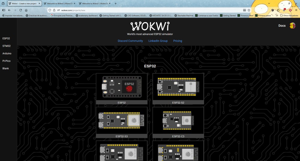
To begin, we'll open the Wokwi main menu to choose which type of microcontroller or board we'll use for our simulation. We'll see several options such as ESP32, STM32, Arduino, and Pi Pico. Something very important here is defining the development platform, that is, the brain of your system. This determines what type of code we'll use and what capabilities our project will have.
Start a new project
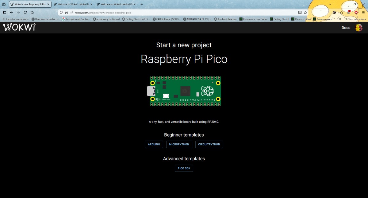
In the following image, I'm on the screen where I'll confirm the start of a new project, Wokwi, using the Raspberry Pi Pico board, which is based on the RP2040 microcontroller the hardware and programming environment to be used in the simulation have already been defined the next step is to establish the complete foundation of the embedded system.
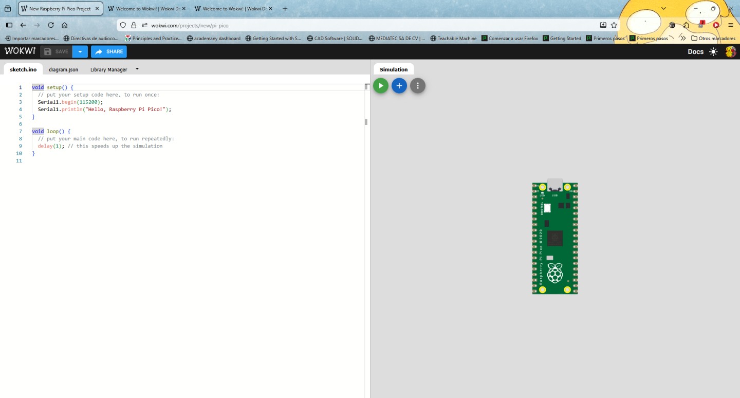
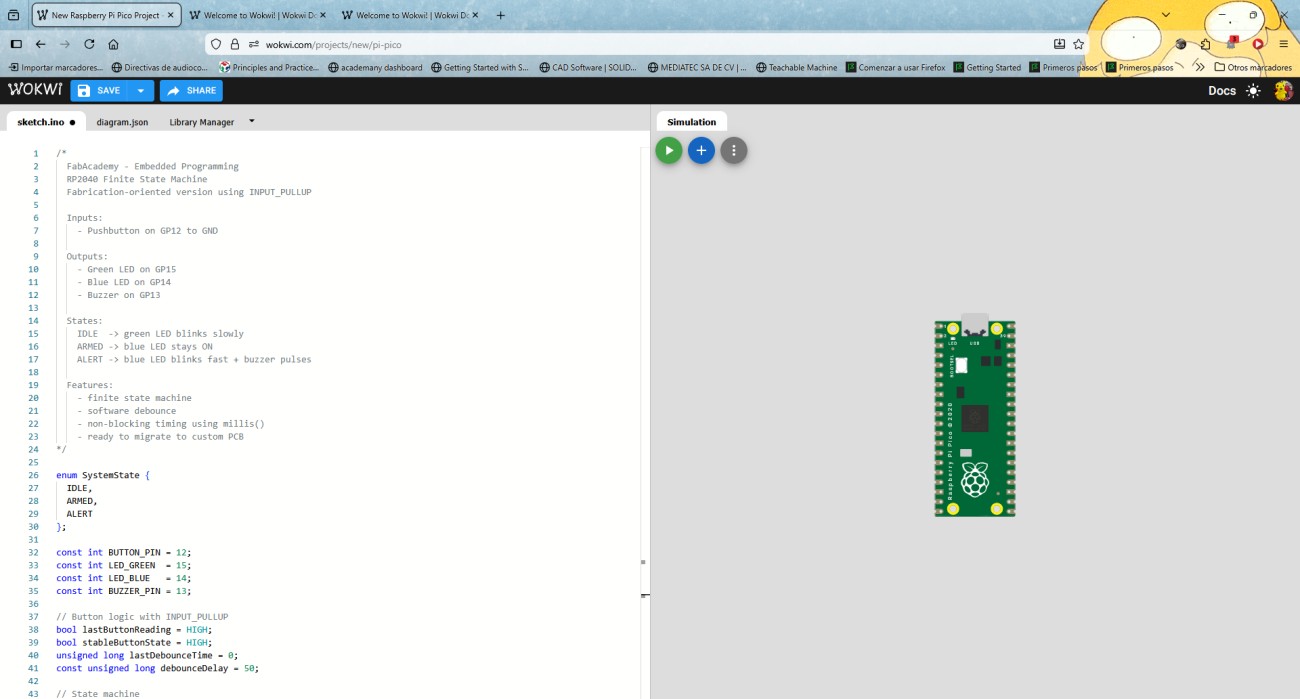
Wowki environment
Once inside the Wokwi working environment, we can see that the screen is divided into two parts: on one side you write the code and on the other you assemble the circuit. At this stage we are working directly with the embedded system and will define how our microcontroller will behave.
Component Configuration
We began building the circuit within the Wokwi simulation environment, adding the necessary components for the operation of our system. For this, I used motors, buttons, resistors, and other electronic devices. By selecting each component, I was able to identify its characteristics and available pins, which allowed me to anticipate how they would interact with the microcontroller.
Circuit simulation
The next step I took was to simulate the circuit. Once all the components were correctly connected and the code implemented, I started the simulation to verify the system's operation in real time. I observed the behavior of the components in response to the developed program, which allowed me to verify that the interaction between the hardware and the software was correct.

	/*
  FabAcademy - Embedded Programming
  RP2040 Finite State Machine
  Fabrication-oriented version using INPUT_PULLUP

  Inputs:
    - Pushbutton on GP12 to GND

  Outputs:
    - Green LED on GP15
    - Blue LED on GP14
    - Buzzer on GP13

  States:
    IDLE  -> green LED blinks slowly
    ARMED -> blue LED stays ON
    ALERT -> blue LED blinks fast + buzzer pulses

  Features:
    - finite state machine
    - software debounce
    - non-blocking timing using millis()
    - ready to migrate to custom PCB
*/

enum SystemState {
  IDLE,
  ARMED,
  ALERT
};

const int BUTTON_PIN = 12;
const int LED_GREEN  = 15;
const int LED_BLUE   = 14;
const int BUZZER_PIN = 13;

// Button logic with INPUT_PULLUP
bool lastButtonReading = HIGH;
bool stableButtonState = HIGH;
unsigned long lastDebounceTime = 0;
const unsigned long debounceDelay = 50;

// State machine
SystemState currentState = IDLE;

// Timing
unsigned long previousLedMillis = 0;
unsigned long previousBuzzerMillis = 0;

// Output states
bool greenLedState = LOW;
bool blueLedState = LOW;
bool buzzerState = LOW;

// Intervals
const unsigned long idleBlinkInterval = 800;
const unsigned long alertBlinkInterval = 150;
const unsigned long alertBuzzerInterval = 200;

void setup() {
  pinMode(BUTTON_PIN, INPUT_PULLUP);
  pinMode(LED_GREEN, OUTPUT);
  pinMode(LED_BLUE, OUTPUT);
  pinMode(BUZZER_PIN, OUTPUT);

  digitalWrite(LED_GREEN, LOW);
  digitalWrite(LED_BLUE, LOW);
  digitalWrite(BUZZER_PIN, LOW);

  Serial.begin(115200);
  delay(300);

  Serial.println("RP2040 FSM Started - Fabrication Version");
  printCurrentState();
}

void loop() {
  handleButton();
  updateStateOutputs();
}

void handleButton() {
  bool reading = digitalRead(BUTTON_PIN);

  if (reading != lastButtonReading) {
    lastDebounceTime = millis();
  }

  if ((millis() - lastDebounceTime) > debounceDelay) {
    if (reading != stableButtonState) {
      stableButtonState = reading;

      // With INPUT_PULLUP, pressed = LOW
      if (stableButtonState == LOW) {
        advanceState();
      }
    }
  }

  lastButtonReading = reading;
}

void advanceState() {
  switch (currentState) {
    case IDLE:
      currentState = ARMED;
      break;
    case ARMED:
      currentState = ALERT;
      break;
    case ALERT:
      currentState = IDLE;
      break;
  }

  resetOutputs();
  printCurrentState();
}

void resetOutputs() {
  greenLedState = LOW;
  blueLedState = LOW;
  buzzerState = LOW;

  digitalWrite(LED_GREEN, LOW);
  digitalWrite(LED_BLUE, LOW);
  digitalWrite(BUZZER_PIN, LOW);

  previousLedMillis = millis();
  previousBuzzerMillis = millis();
}

void updateStateOutputs() {
  unsigned long currentMillis = millis();

  switch (currentState) {
    case IDLE:
      digitalWrite(LED_BLUE, LOW);
      digitalWrite(BUZZER_PIN, LOW);

      if (currentMillis - previousLedMillis >= idleBlinkInterval) {
        previousLedMillis = currentMillis;
        greenLedState = !greenLedState;
        digitalWrite(LED_GREEN, greenLedState);
      }
      break;

    case ARMED:
      digitalWrite(LED_GREEN, LOW);
      digitalWrite(BUZZER_PIN, LOW);
      digitalWrite(LED_BLUE, HIGH);
      break;

    case ALERT:
      digitalWrite(LED_GREEN, LOW);

      if (currentMillis - previousLedMillis >= alertBlinkInterval) {
        previousLedMillis = currentMillis;
        blueLedState = !blueLedState;
        digitalWrite(LED_BLUE, blueLedState);
      }

      if (currentMillis - previousBuzzerMillis >= alertBuzzerInterval) {
        previousBuzzerMillis = currentMillis;
        buzzerState = !buzzerState;
        digitalWrite(BUZZER_PIN, buzzerState);
      }
      break;
  }
}

void printCurrentState() {
  Serial.print("Current state: ");

  switch (currentState) {
    case IDLE:
      Serial.println("IDLE");
      break;
    case ARMED:
      Serial.println("ARMED");
      break;
    case ALERT:
      Serial.println("ALERT");
      break;
  }
}