

My Final Project: The Campus ROVER
P5 - Firmware & Software Development
Getting the ESP32 ready!
The campusROVER wouldn't work at all if it wasn't for the firmware, programmed in the microcontroller, that makes for all of its functions.
The ESP32 is a very powerful and versatile microcontroller, and it is compatible with the Arduino programming environment, but if you are using the ESP32 as a standalone component, without the support from a commercial board like in my case, the programming process is not as straightforward as you may think.
These chips new from factory often come with nothing preloaded, and a very important feature we need to interact with it is the Bootloader! We can't install the bootloader directly from Arduino as we can with other architectures such as AVR microcontrollers, instead we have to use Espressif's tailor-made software called ESP-IDF.
You can look how to install such software (its a whole process) in this link here: Install ESP-IDF
Once you have ESP-IDF installed, you need a serial programmer such as this one with an FTDI chip on board:
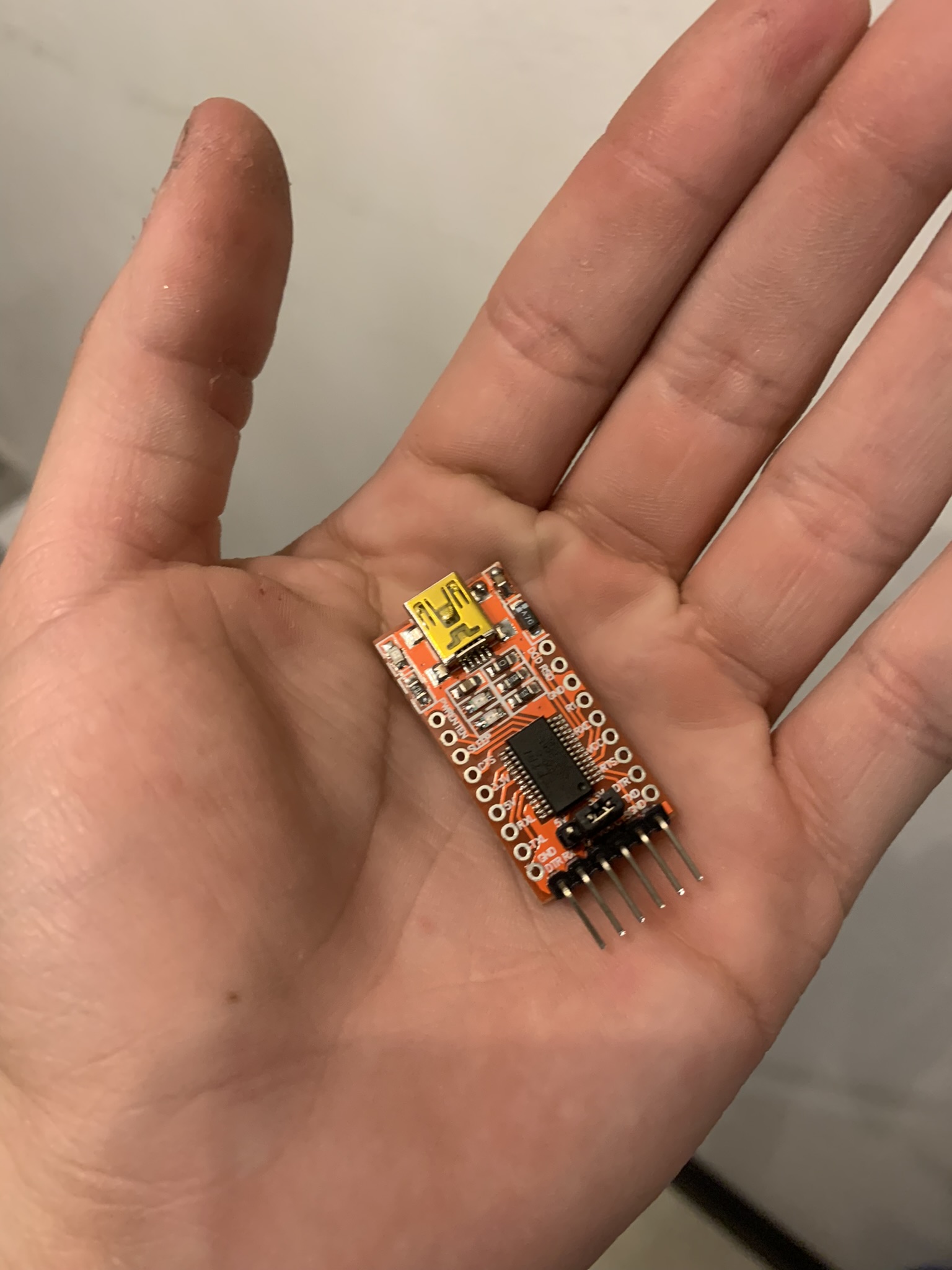
For this board you may also need drivers, which you can find here: Download FTDI Drivers
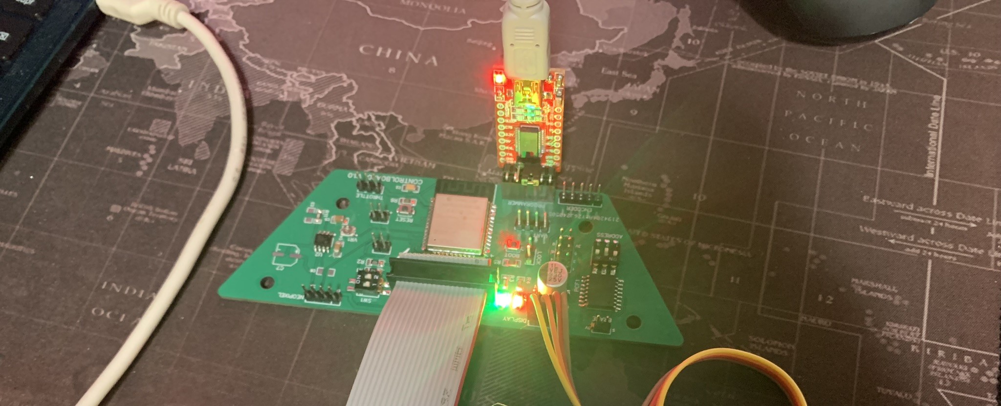
The controlboard, which is the only one that needs programming, is designed to easily connect via a dedicated port to this specific programmer, if other programmer is used pinouts may change and connections will be not as direct.
The programmer connects as shown in the image below. The controlboard must be also connected to the powerboard via the 20-way flat cable to obtain power!
Once connections are done and ESP-IDF is correctly installed, we can start uploading the bootloader! We first open a command prompt window and execute the following command to open a simple example from the ESP-IDF example library:
cd esp-idf/examples/get-started/hello_world
Then we configure said proyect for our hardware:
	idf.py set-target esp32
	idf.py menuconfig
Then we build the proyect, which will generate the bootloader, memory partitions and firmware:
idf.py build
Then it's time to flash our ESP32. Make sure everything's properly connected, the correct COM port is selected and that the microcontroller is set onto programming mode, this is done by pulling GPIO 0 to ground, or in my board's case, by pressing the "BOOT" button once.
idf.py -p COM3 flash
If done right, this procedure should leave the ESP32 ready to rock!
Programming using Arduino:
Once the bootloader is installed, using the Arduino IDE to program this board is really easy. We have to first install the ESP boards onto our IDE going into preferences and pasting the following URL into the box titled "Additional Boards Manager URLs".
https://dl.espressif.com/dl/package_esp32_index.json
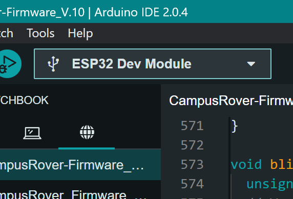
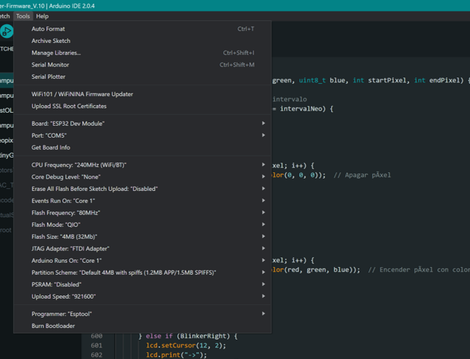
An installation window will pop-up, and after it is finished we are ready to go! We just need to select the board, in this case the "ESP32 Dev Module" is used with the following configurations on the arduino IDE:
The campusROVER Firmware:
The firmware for the campusROVER is a fairly complex piece of code, which I will explain section by section:
1. Include Libraries:
			#include Arduino.h
			#include Wire.h
			#include "driver/dac.h"
			#include math.h
			#include Adafruit_PCF8574.h
			#include "esp32-hal-timer.h"
			#include "SingleEMAFilterLib.h"
			#include LiquidCrystal_I2C.h
			#include BigNumbers_I2C.h
			#include TinyGPSPlus.h
			#include HardwareSerial.h
			#include Adafruit_NeoPixel.h
This section includes all the necessary libraries for the scooter's functionalities such as I2C communication, LCD display, GPS, NeoPixels, and motor control.
2. Object Initialization and Definitions:
			Adafruit_PCF8574 AuxPCF;
			Adafruit_PCF8574 MotorPCF;
			SingleEMAFilter AcceleratorFilter(0.1);
			SingleEMAFilter BatVoltageFilter(0.2);

			#define NUMPIXELS 16

			HardwareSerial SerialGPS(1);
			TinyGPSPlus gps;
This section initializes objects for controlling the two on-board PCF8574 GPIO extenders, filtering analog inputs using matemathical filters, handling NeoPixels, and managing GPS data.
3. MCU Pin Definitions:
			#define TACHOMETER1_INPUT 23
			#define I2C_SCL 22
			#define UART_TX0 1
			#define UART_RX0 3
			#define I2C_SDA 21
			#define ENCODER_CLOCK 19
			#define BLINKER_LEFT 18
			#define BLINKER_RIGHT 5
			#define UART_TX2 17
			#define UART_RX2 16
			#define VOLTAGE_MONITOR_3V3 4
			#define ENABLE_PIN 0
			#define MOTOR_A_PWM 15
			#define MOTOR_B_PWM 14
			#define BATTERY_VOLTAGE_MONITOR 34
			#define VOLTAGE_MONITOR_5V 35
			#define REGULATOR_CONTROL_3V3 32
			#define TACHOMETER2_INPUT 33
			#define DAC_OUTPUT 25
			#define DAC_CHANNEL DAC_CHANNEL_1
			#define REGULATOR_CONTROL_5V 26
			#define NEOPIXEL_SIGNAL 27
			#define FAN_PWM 13
			#define THROTTLE_SIGNAL 12
			#define ENABLE_BRIDGE1 4
			#define ENABLE_BRIDGE2 1
			#define BRAKE_SIGNAL 1
			#define KEY_1 2
			#define KEY_2 3
			#define KEY_3 4
			#define KEY_4 5
			#define PCF_ERROR 101
This section defines all the pin numbers used for various sensors, actuators, and communication interfaces. It is basically a list to know what is connected where on the microcontroller.
4. LCD and Neopixel Initialization:
			LiquidCrystal_I2C lcd(0x27, 20, 4);
			BigNumbers_I2C bigNum(&lcd);
			Adafruit_NeoPixel pixels(NUMPIXELS, NEOPIXEL_SIGNAL, NEO_GRB + NEO_KHZ800);
Initialization of the LCD and NeoPixel strip objects with their respective parameters, as well as the BigNumbers object, which serves the purpose of displaying larger numbers on the LCD screen!
5. Global Variable Initialization:
			const long NormalReadings = 50;
			float WheelDiameter = 0.25;
			float WheelCircumference = 3.1415 * WheelDiameter;

			const int PWM_FREQ = 440;
			const int PWM_RESOLUTION = 8;
			const uint32_t GPSBaud = 9600;
			int TimezoneOffset = -6;
			const unsigned long debounceDelay = 20;

			unsigned long previousMillisNeo = 0;
			const long intervalNeo = 400;
			bool pixelsOn = false;

			int Speed = 0;
			int TachoRPM = 0;
			int TachoSpeed = 0;
			int ThrottleRead = 0;
			int Throttle = 0;
			int ThrottlePercent = 0;
			int FilterThrottle = 0;
			float BatteryVoltage = 0;
			float totalDistance = 0;
			int MenuSelect = 0;
			int MaxThrottle = 255;
			bool EcoMode = false;

			bool LatchState1 = false;
			bool LatchState2 = false;

			volatile int Pulse = 0;
			volatile unsigned long lastDebounceTime = 0;
			volatile long totalRevolutions = 0;

			bool BrakePressed = false;
			bool TachometerApulse = false;

			int DiagnosticError = 0;
			hw_timer_t *timer1 = NULL;
			hw_timer_t *timer2 = NULL;
			volatile bool flag1 = false;
			volatile bool flag2 = false;

			int ClockHour = 0;
			int ClockMinute = 0;
			int ClockSecond = 0;

			int GPSYear = 0;
			int GPSMonth = 0;
			int GPSDay = 0;

			float GPSlatitude = 0;
			float GPSlongitude = 0;

			int GPSspeed = 0;

			bool BlinkerLeft = false;
			bool BlinkerRight = false;
			bool WarningLights = false;

			bool lastButtonState = LOW;
			bool latchState = LOW;
			unsigned long lastDebounceTime2 = 0;
			const unsigned long debounceDelay2 = 50;
All the global variables used inside the program are declared here, from sensor readings and GPS positioning to simple state flags. In this section, timers are also configured.
6. Interrupt Service Routines:
			void IRAM_ATTR onTimer1() {
				flag1 = true;
			  }

			  void IRAM_ATTR onTimer2() {
				flag2 = true;
			  }

			  void IRAM_ATTR handleTachometerInterrupt() {
				unsigned long currentTime = millis();
				if ((currentTime - lastDebounceTime) > debounceDelay) {
				  Pulse++;
				  lastDebounceTime = currentTime;
				}
			  }
ISR's are used to manage microcontroller pin interrupts, which in this case serve as pulse detectors for the tachometer. These functions set flags or increment counters when specific events occur.
7. Setup Function:
			void setup() {
				Serial.begin(115200);
				SerialGPS.begin(GPSBaud, SERIAL_8N1, UART_RX2, UART_TX2);

				Wire.begin();
				pixels.begin();
				pixels.show();

				lcd.init();
				lcd.backlight();
				bigNum.begin();

				scanI2C();
				if (!AuxPCF.begin(0x26, &Wire)) {
				  Serial.println("Error initializing PCF8574 Aux");
				  DiagnosticError = PCF_ERROR;
				}
				if (!MotorPCF.begin(0x21, &Wire)) {
				  Serial.println("Error initializing PCF8574 Motor");
				  DiagnosticError = PCF_ERROR;
				}

				AuxPCF.pinMode(BRAKE_SIGNAL, INPUT_PULLUP);
				AuxPCF.pinMode(KEY_1, INPUT_PULLUP);
				AuxPCF.pinMode(KEY_2, INPUT_PULLUP);
				AuxPCF.pinMode(KEY_3, INPUT_PULLUP);
				AuxPCF.pinMode(KEY_4, INPUT_PULLUP);
				MotorPCF.pinMode(ENABLE_BRIDGE1, OUTPUT);
				MotorPCF.pinMode(ENABLE_BRIDGE2, OUTPUT);
				MotorPCF.digitalWrite(ENABLE_BRIDGE1, LOW);
				MotorPCF.digitalWrite(ENABLE_BRIDGE2, LOW);

				pinMode(TACHOMETER1_INPUT, INPUT_PULLDOWN);
				pinMode(TACHOMETER2_INPUT, INPUT_PULLDOWN);
				pinMode(BLINKER_LEFT, INPUT_PULLDOWN);
				pinMode(BLINKER_RIGHT, INPUT_PULLDOWN);
				attachInterrupt(digitalPinToInterrupt(TACHOMETER2_INPUT), handleTachometerInterrupt, RISING);

				ledcSetup(0, PWM_FREQ, PWM_RESOLUTION);
				ledcAttachPin(MOTOR_A_PWM, 0);

				ledcSetup(1, PWM_FREQ, PWM_RESOLUTION);
				ledcAttachPin(MOTOR_B_PWM, 1);

				delay(2000);

				if (DiagnosticError > 0) {
				  Serial.println("System Error");
				  while (1);
				}

				Serial.println("All Systems OK");
				generateTone(DAC_CHANNEL, 440, 1000);
				delay(1000);

				timer1 = timerBegin(0, 80, true);
				timerAttachInterrupt(timer1, &onTimer1, true);
				timerAlarmWrite(timer1, 50000, true);
				timerAlarmEnable(timer1);

				timer2 = timerBegin(1, 80, true);
				timerAttachInterrupt(timer2, &onTimer2, true);
				timerAlarmWrite(timer2, 200000, true);
				timerAlarmEnable(timer2);
			  }
This code section only executes once when the MCU starts running. The setup function initializes serial communication, I2C, NeoPixels, LCD, PCF8574 GPIO expanders, pin modes, and timers. It also performs an I2C bus scan and checks for initialization errors.
8. Main Loop Function:
			void loop() {
				BlinkerLeft = digitalRead(BLINKER_LEFT);
				BlinkerRight = digitalRead(BLINKER_RIGHT);

				if (flag1) {
				  flag1 = false;
				  ReadThrottle();
				  BatteryVoltage = getBatVoltage();

				  BrakePressed = AuxPCF.digitalRead(BRAKE_SIGNAL);
				  ledcWrite(0, Throttle);  // Motor A
				  ledcWrite(1, Throttle);  // Motor B
				  ReadGPS();
				}

				if (flag2) {
				  flag2 = false;
				  MeasureSpeed();
				  UpdateScreen();
				}

				handleNeoPixels();
				handleKeys();
			  }
The main loop continuously checks the state of the blinkers and handles tasks based on timer flags, such as reading the throttle, updating battery voltage, controlling motors, reading GPS data, measuring speed, and updating the LCD screen. It also manages the key presses and every other subsystem on the microcontroller.
9. Neopixel Handler:
			void handleNeoPixels() {
				if (BlinkerRight && !BlinkerLeft && BrakePressed && !WarningLights) {
				  blinkNeoPixels(255, 50, 0, 8, 16);
				} else if (!BlinkerRight && BlinkerLeft && BrakePressed && !WarningLights) {
				  blinkNeoPixels(255, 50, 0, 0, 7);
				} else if (!BrakePressed && !BlinkerLeft && !BlinkerRight && !WarningLights) {
				  lightUpRed();
				} else if (BrakePressed && !BlinkerLeft && !BlinkerRight && WarningLights) {
				  blinkNeoPixels(255, 0, 0, 0, 16);
				} else if (BrakePressed && !BlinkerRight && !BlinkerLeft && !WarningLights) {
				  turnOffPixels();
				}
			  }
This function handles the NeoPixel LEDs based on the state of the blinkers, brake, and warning lights.
10. Dashboard Keys Handler:
			void handleKeys() {
				if (!AuxPCF.digitalRead(KEY_1)) {
				  generateTone(DAC_CHANNEL, 5000, 50);
				  lcd.clear();
				  MenuSelect++;
				  delay(200);
				  if (MenuSelect > 1) {
					MenuSelect = 0;
				  }
				} else if (!AuxPCF.digitalRead(KEY_2)) {
				  generateTone(DAC_CHANNEL, 5000, 50);
				  LatchState1 = !LatchState1;
				  WarningLights = LatchState1;
				  delay(200);
				} else if (!AuxPCF.digitalRead(KEY_3)) {
				  generateTone(DAC_CHANNEL, 5000, 50);
				  LatchState2 = !LatchState2;
				  EcoMode = LatchState2;
				  delay(200);
				} else if (!AuxPCF.digitalRead(KEY_4)) {
				  generateTone(DAC_CHANNEL, 5000, 50);
				  LatchState2 = !LatchState2;
				  EcoMode = LatchState2;
				  delay(200);
				}
			  }
This function handles the input from the keys, updating the menu, toggling warning lights, and switching between normal and eco modes. ECO mode limits the maximum throttle signal to about 70%.
11. I2C Bus Scanner:
			void scanI2C() {
				byte error, address;
				int nDevices;

				Serial.println("Scanning I2C bus...");

				nDevices = 0;
				for (address = 1; address < 127; address++) {
				  Wire.beginTransmission(address);
				  error = Wire.endTransmission();

				  if (error == 0) {
					Serial.print("I2C device found at address 0x");
					if (address < 16) Serial.print("0");
					Serial.print(address, HEX);
					Serial.println(" !");

					nDevices++;
				  } else if (error == 4) {
					Serial.print("Unknown error at address 0x");
					if (address < 16) Serial.print("0");
					Serial.println(address, HEX);
				  }
				}
				if (nDevices == 0)
				  Serial.println("No I2C devices found\n");
				else
				  Serial.println("I2C scan completed\n");
			  }
This function scans the I2C bus for connected devices and prints their addresses. The system has various i2C systems connected, so having this implemented results very useful when debugging and looking for hardware problems.
12. Throttle Reading and Processing:
			void ReadThrottle() {
				if (EcoMode) {
				  MaxThrottle = 150;
				} else {
				  MaxThrottle = 255;
				}

				ThrottleRead = analogRead(THROTTLE_SIGNAL);
				AcceleratorFilter.AddValue(ThrottleRead);
				FilterThrottle = AcceleratorFilter.GetLowPass();
				int PreThrottle = map(FilterThrottle, 2960, 2680, 0, MaxThrottle);
				Throttle = constrain(PreThrottle, 0, MaxThrottle);
				float DivThrottle = constrain(PreThrottle, 0, MaxThrottle);
				ThrottlePercent = round((DivThrottle / 255) * 100);

				if (!BrakePressed || ThrottlePercent == 0) {
				  MotorPCF.digitalWrite(ENABLE_BRIDGE1, 0);
				  MotorPCF.digitalWrite(ENABLE_BRIDGE2, 0);
				} else {
				  MotorPCF.digitalWrite(ENABLE_BRIDGE1, 1);
				  MotorPCF.digitalWrite(ENABLE_BRIDGE2, 1);
				}
			  }
This function reads the throttle position, applies a filter to smooth the data coming from the analog port, maps the filtered value to a throttle percentage, and updates the motor control based on the throttle and brake status. As a safety feature, the throttle lever signal is ignored when the brake is pressed.
13. Tone Generation:
			void generateTone(dac_channel_t channel, int freq, int duration) {
				dac_output_enable(channel);

				int period = 1000000 / freq;
				int halfPeriod = period / 2;
				int cycles = (duration * 1000) / period;

				for (int i = 0; i < cycles; i++) {
				  dac_output_voltage(channel, 255);
				  delayMicroseconds(halfPeriod);
				  dac_output_voltage(channel, 0);
				  delayMicroseconds(halfPeriod);
				}

				dac_output_disable(channel);
			  }
This function generates a tone using the DAC by toggling the output voltage at a specified frequency and duration. This sounds are amplified by the onboard amplifier circuit and sent to the speaker to provide acoustic feedback for the user.
14. Battery Voltage Reading:
			float getBatVoltage() {
				float Reading = analogRead(BATTERY_VOLTAGE_MONITOR);
				BatVoltageFilter.AddValue((Reading / 4095) * 33.33);
				float Voltage = BatVoltageFilter.GetLowPass();
				return Voltage;
			  }
This function reads the battery voltage, applies a filter to smooth the reading, and returns the filtered voltage value. The voltage signal comes from a voltage divider in the powerboard, which drops the voltage from around 30V (battery max) and converts it proportionally in a range from 0 to 3.3V, which the MCU can safely read. The mapped readings are then processed to obtain a real voltage measurement.
15. LCD Screen Update:
			void UpdateScreen() {
				switch (MenuSelect) {
				  case 0:
					lcd.setCursor(0, 0);
					lcd.print(BatteryVoltage);
					lcd.print("V ");
					lcd.print("    ");

					lcd.setCursor(15, 3);
					lcd.print(ThrottlePercent);
					lcd.print("% ");
					drawProgressBar(3, 0, 14, ThrottlePercent, 100, 0);

					bigNum.displayLargeInt(TachoSpeed, 7, 0, 4, false);
					lcd.setCursor(15, 2);
					lcd.print("km/h");

					lcd.setCursor(0, 1);
					lcd.print(totalDistance / 1000);
					lcd.print("km  ");

					lcd.setCursor(0, 2);
					lcd.print(TachoRPM);
					lcd.print("RPM  ");

					if (EcoMode) {
					  lcd.setCursor(9, 2);
					  lcd.print("ECO");
					} else {
					  lcd.setCursor(9, 2);
					  lcd.print("   ");
					}
					break;

				  case 1:
					bigNum.displayLargeInt(TachoSpeed, 7, 0, 4, false);
					lcd.setCursor(15, 2);
					lcd.print("km/h");

					lcd.setCursor(0, 2);
					lcd.print("Lat: ");
					lcd.print(GPSlatitude);
					lcd.print(" ");
					lcd.setCursor(0, 3);
					lcd.print("Lng: ");
					lcd.print(GPSlongitude);
					lcd.print(" ");

					lcd.setCursor(0, 1);
					if (ClockHour < 10) {
					  lcd.print("0");
					  lcd.print(ClockHour);
					} else {
					  lcd.print(ClockHour);
					}
					lcd.print(":");
					if (ClockMinute < 10) {
					  lcd.print("0");
					  lcd.print(ClockMinute);
					} else {
					  lcd.print(ClockMinute);
					}
					break;
				}
			  }
This function updates the LCD screen with various data such as battery voltage, throttle percentage, speed, distance, RPM, GPS coordinates, and clock time based on the selected menu. As we dont want to update the screen with every MCU's cycle, which would be computationally intensive, this function only updates the screen every 500ms using a hardware timer.
16. GPS Reading:
			void ReadGPS() {
				while (SerialGPS.available() > 0) {
				  char c = SerialGPS.read();
				  gps.encode(c);

				  if (gps.location.isUpdated()) {
					GPSlatitude = gps.location.lat();
					GPSlongitude = gps.location.lng();
				  }

				  if (gps.date.isUpdated()) {
					GPSYear = gps.date.year();
					GPSMonth = gps.date.month();
					GPSDay = gps.date.day();
				  }

				  if (gps.time.isUpdated()) {
					ClockHour = gps.time.hour() + TimezoneOffset;
					if (ClockHour < 0) {
					  ClockHour += 24;
					} else if (ClockHour >= 24) {
					  ClockHour -= 24;
					}
					ClockMinute = gps.time.minute();
					ClockSecond = gps.time.second();
				  }
				  if (gps.speed.isUpdated()) {
					GPSspeed = gps.speed.kmph();
				  }
				}
			  }
This function reads data from the GPS module using the TinyGPS library. It updates the latitude, longitude, date, time, and GPS speed onto global variables.
17. Speed Measurement:
			void MeasureSpeed() {
				static unsigned long previousTime = 0;
				unsigned long currentTime = millis();

				if ((currentTime - previousTime) >= 1000) {
				  noInterrupts();
				  int pulseCount = Pulse;
				  Pulse = 0;
				  interrupts();

				  TachoRPM = (pulseCount * 60.0) / 5;
				  TachoSpeed = ((pulseCount / 5.0) * WheelCircumference) * 3.6;

				  long revolutions = pulseCount / 5;
				  totalRevolutions += revolutions;

				  float totalDistance = totalRevolutions * WheelCircumference;
				  previousTime = currentTime;
				}
			  }
The speed measurement logic involves counting pulses from a Hall sensor, which are generated by magnets mounted on the wheel. By counting the pulses over a fixed time interval (one second), the program calculates the number of wheel revolutions per minute (RPM) and the speed in kilometers per hour (km/h). The code also tracks the total distance traveled by accumulating the total number of wheel revolutions. This method results in somewhat accurate speed measurement and distance tracking, given the fixed number of magnets and known wheel circumference.
18. Progress Bar Drawing:
			void drawProgressBar(int row, int col, int maxLength, int value, int minValue, int maxValue) {
				int percent = map(value, minValue, maxValue, 0, 100);
				int numBlocks = (percent * maxLength) / 100;
				int partialBlock = ((percent * maxLength) % 100) / 12.5;

				lcd.setCursor(col, row);

				for (int i = 0; i < numBlocks; i++) {
				  lcd.write(byte(5));
				}

				if (numBlocks < maxLength) {
				  lcd.write(byte(partialBlock));
				  numBlocks++;
				}

				for (int i = numBlocks; i < maxLength; i++) {
				  lcd.write(byte(0));
				}
			  }
This function draws a progress bar on the LCD to visually represent values such as the throttle percentage. This is useful to visually convey to the user the amount of throttle that is being applied to the motors.
19. Neopixel Lighting:
			void lightUpRed() {
				for (int i = 0; i < 16; i++) {
				  pixels.setPixelColor(i, pixels.Color(255, 0, 0));
				}
				pixels.show();
			  }

			  void turnOffPixels() {
				for (int i = 0; i < NUMPIXELS; i++) {
				  pixels.setPixelColor(i, pixels.Color(0, 0, 0));
				}
				pixels.show();
			  }

			  void blinkNeoPixels(uint8_t red, uint8_t green, uint8_t blue, int startPixel, int endPixel) {
				unsigned long currentMillis = millis();
				if (currentMillis - previousMillisNeo >= intervalNeo) {
				  previousMillisNeo = currentMillis;

				  if (pixelsOn) {
					for (int i = startPixel; i <= endPixel; i++) {
					  pixels.setPixelColor(i, pixels.Color(0, 0, 0));
					}
					generateTone(DAC_CHANNEL, 2000, 5);
					lcd.setCursor(7, 2);
					lcd.print("  ");
					lcd.setCursor(12, 2);
					lcd.print("  ");
					pixelsOn = false;
				  } else {
					for (int i = startPixel; i <= endPixel; i++) {
					  pixels.setPixelColor(i, pixels.Color(red, green, blue));
					}
					pixelsOn = true;
					generateTone(DAC_CHANNEL, 2500, 5);
					if (BlinkerLeft) {
					  lcd.setCursor(7, 2);
					  lcd.print("<-");
					} else if (BlinkerRight) {
					  lcd.setCursor(12, 2);
					  lcd.print("->");
					} else if (WarningLights) {
					  lcd.setCursor(12, 2);
					  lcd.print("->");
					  lcd.setCursor(7, 2);
					  lcd.print("<-");
					}
				  }
				  pixels.show();
				}
			  }
These functions control the NeoPixel LEDs, including turning them red, turning them off, and blinking them based on the input signals. It also handles concurrent states, like when the brake lever is pressed while using the turn signals.
Final Results:
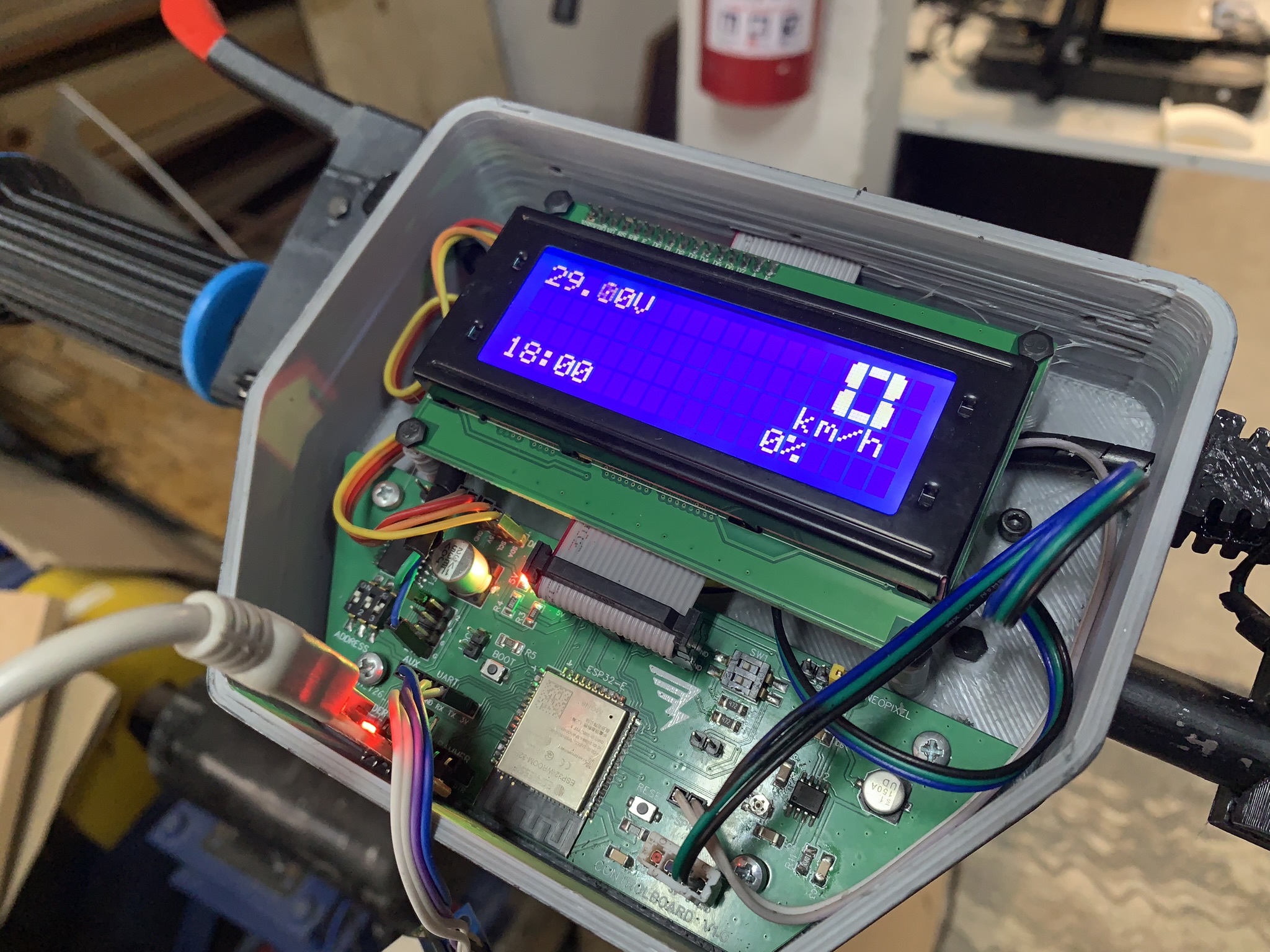
Uploading this code to the controlboard should result in the LCD display lighting up and showing the chosen info.
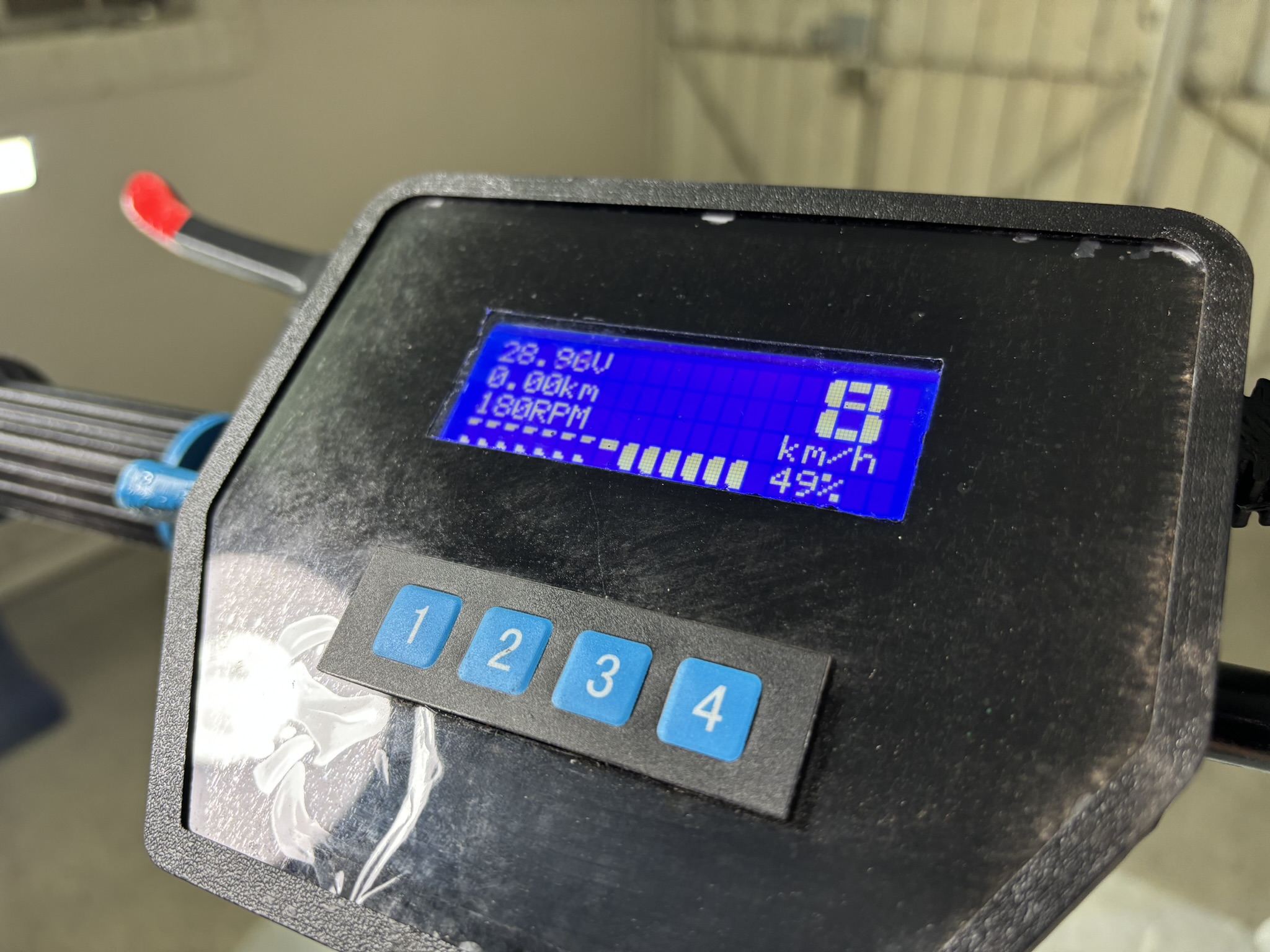
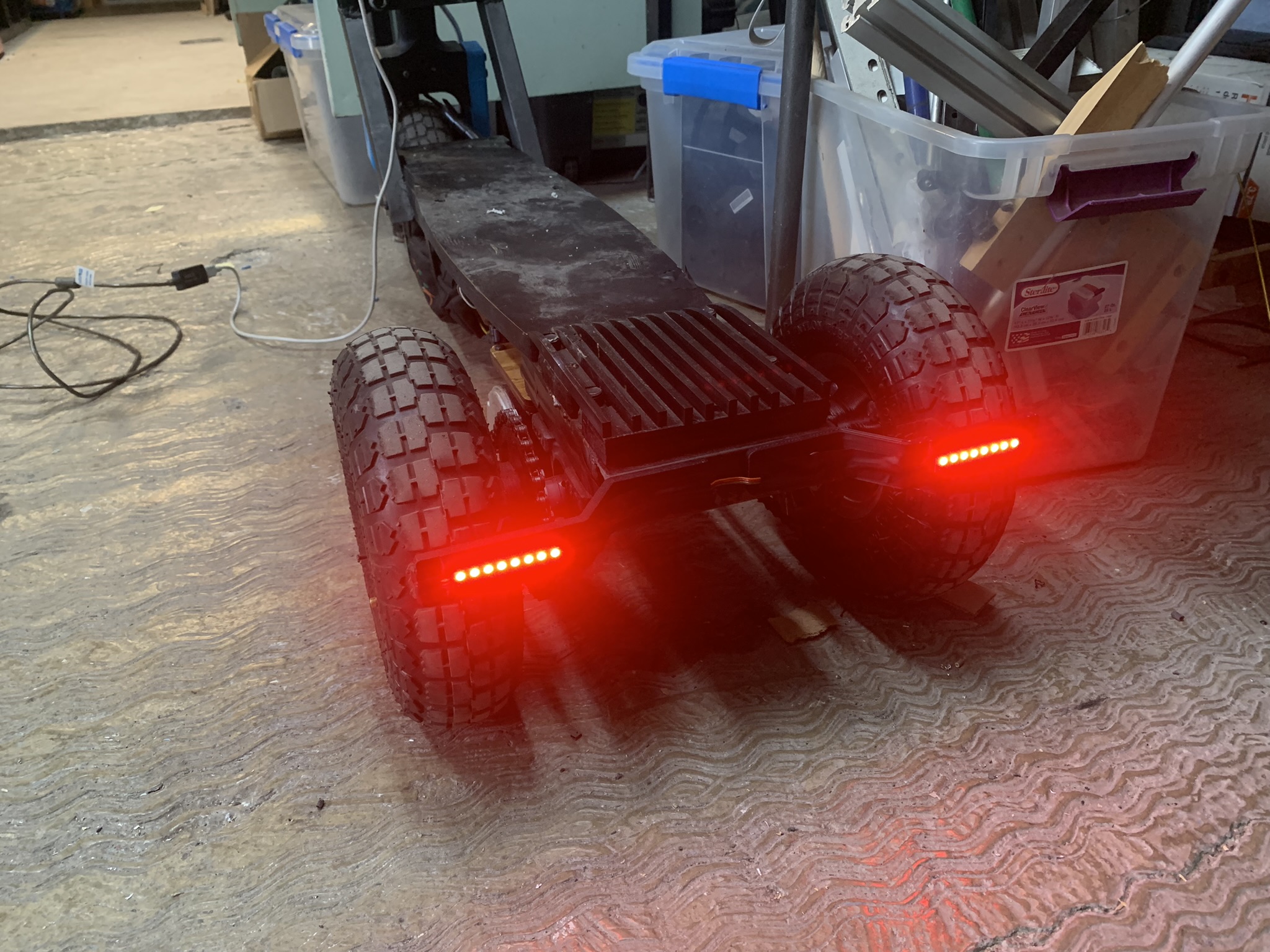
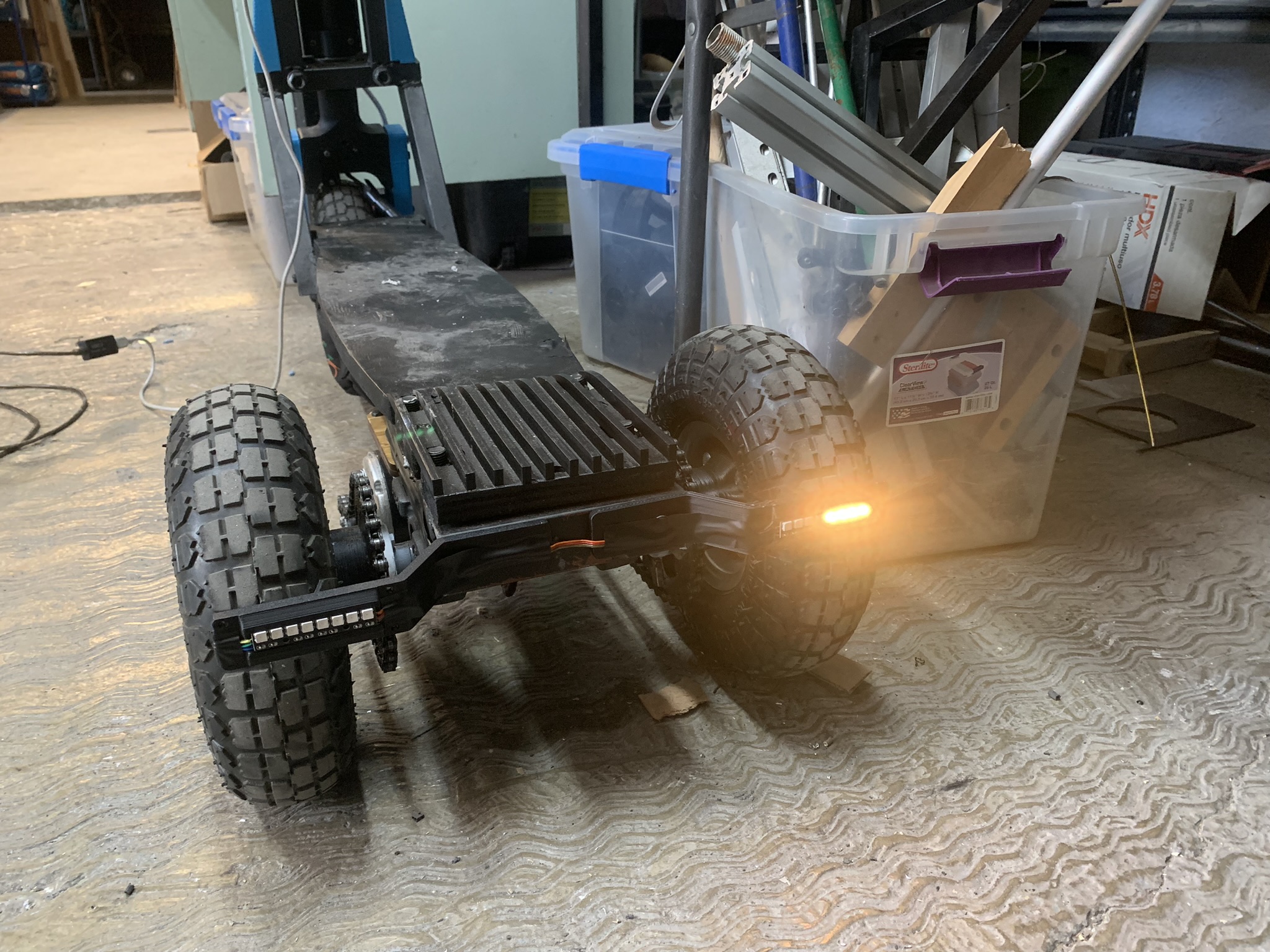
The motors should also spin proportional to the pressing of the throttle lever, and the brake and turn signals should work as expected:

Thank you for checking out my final proyect's construction and development process! Return to Index
Download all final proyect assets here!