13. Networking and communications
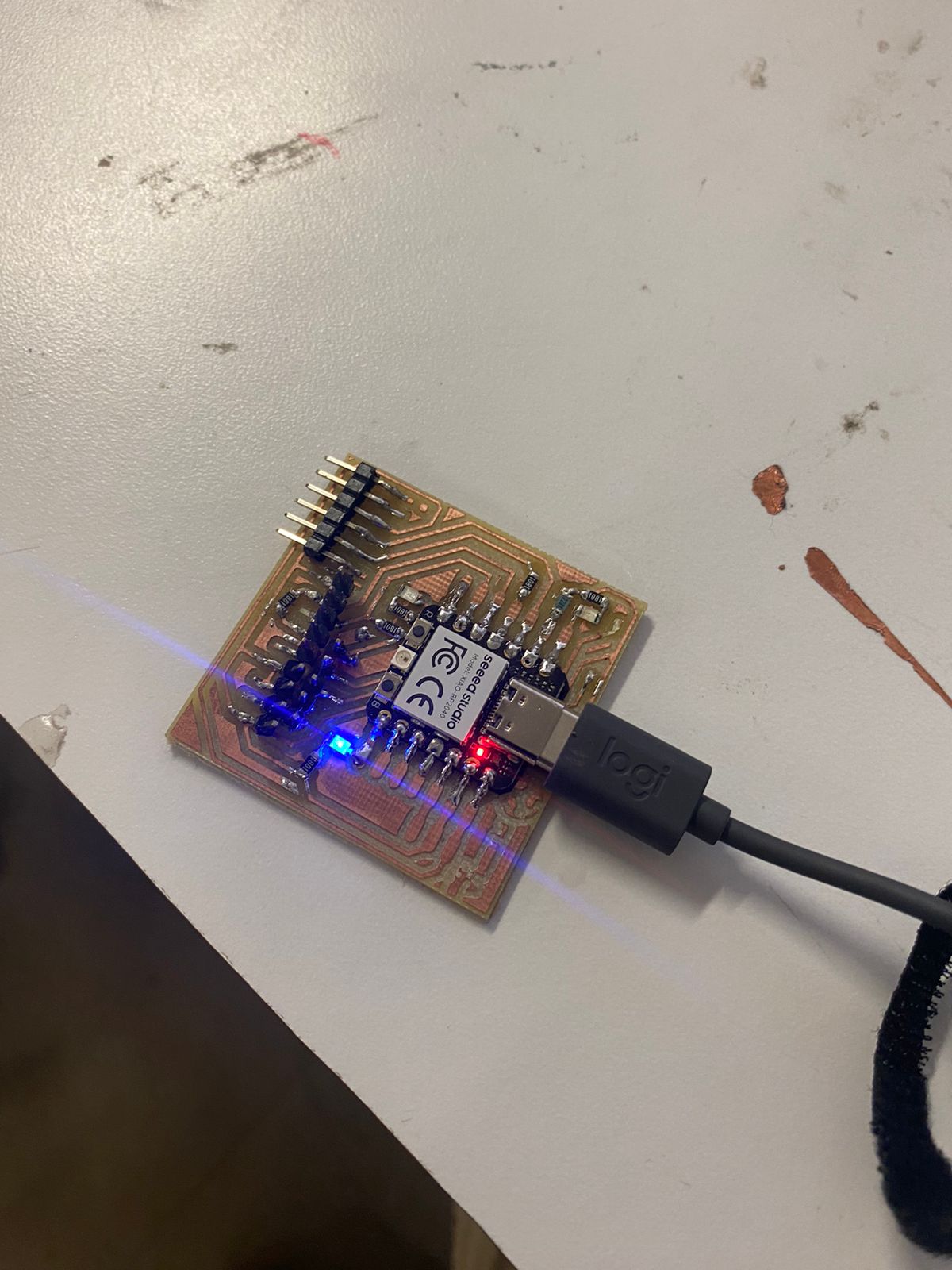
this week i worked on programming different PCB so that they would work together
THIS WEEK GROUP ASSIGNMENT(click the title)
TYPES OF COMUNICATIONS
There exist many types of comunication methods between devices such as I^2C, UART, SPI and many more but I decide to use the easiest which is I^2C
I²C (Inter-Integrated Circuit) is a serial communication protocol that allows multiple devices to communicate with each other using just two wires: SCL (clock) and SDA (data).
Hardware Setup
- Master (RP32C2): Connect SCL (Pin A5) and SDA (Pin A4) to the corresponding pins on the RP2040 boards.
- Slave (RP2040): Connect SCL (Pin 13) and SDA (Pin 12) to the corresponding pins on the RP32C2 and each other.
- Ensure all boards are powered appropriately.
Protocol Overview
The master initiates communication by sending a start condition followed by the 7-bit address of the slave it wants to communicate with, and a read/write bit. The slaves respond to commands from the master, and data exchange occurs as needed.

Example Code (Arduino on RP32C2)
Below is an example Arduino sketch to demonstrate using the RP32C2 as a master to control LEDs on the RP2040 slaves:
Master coding (RP32c2)
				#include


					void setup() {

					  Wire.begin(); // Inicia el maestro I2C


					  Serial.begin(115200);

					  delay(1000); // Tiempo para inicializar

					}


					void loop() {

					  if (Serial.available()) {

						char command = Serial.read();

						sendCommandToSlave(8, command); // Dirección del esclavo RP2040

					  }

					}


					void sendCommandToSlave(byte address, char command) {

					  Wire.beginTransmission(address);

					  Wire.write(command);

					  Wire.endTransmission();

					  delay(100); // Pequeña pausa para asegurar la transmisión

					}

				Slave coding (Rp2040)

						#include


							#define LED_TX_PIN 0 // Pin del LED conectado al TX

							#define LED_RX_PIN 1 // Pin del LED conectado al RX


							void setup() {

							  pinMode(LED_TX_PIN, OUTPUT);

							  pinMode(LED_RX_PIN, OUTPUT);


							  Wire.begin(8); // Dirección I2C del esclavo

							  Wire.onReceive(receiveEvent);

							}


							void loop() {

							  // Nada que hacer aquí, todo se maneja en receiveEvent

							}


							void receiveEvent(int howMany) {

							  while (Wire.available()) {

								char c = Wire.read();

								switch (c) {

								  case 'T':

									digitalWrite(LED_TX_PIN, !digitalRead(LED_TX_PIN));

									break;

								  case 'R':

									digitalWrite(LED_RX_PIN, !digitalRead(LED_RX_PIN));

									break;

								}
							  }
							}
Explanation
The provided Arduino code showcases a master-slave communication setup using the I2C protocol facilitated by the Wire library. In the master code, upon initialization (setup()), the I2C bus is started (Wire.begin()), and serial communication is initiated for debugging purposes (Serial.begin(115200)). The loop() function continuously checks for available data on the serial port (Serial.available()). When data is received, it reads the command character and sends it to the slave device (RP2040) via the sendCommandToSlave() function. This function begins an I2C transmission to the slave address (8), writes the command, and ends the transmission after a brief delay to ensure completion.
On the slave side, in the setup() function, the pins connected to LEDs (TX and RX indicators) are configured as outputs using pinMode(). The I2C bus is initialized as a slave with address 8 (Wire.begin(8)), and an event handler (Wire.onReceive(receiveEvent)) is registered to handle incoming data. The loop() function remains empty since all data handling is managed by the receiveEvent() function. When data is received from the master, the receiveEvent() function is triggered. It reads the incoming character (Wire.read()) and toggles the corresponding LED based on the received command ('T' for TX LED and 'R' for RX LED) using digitalWrite()
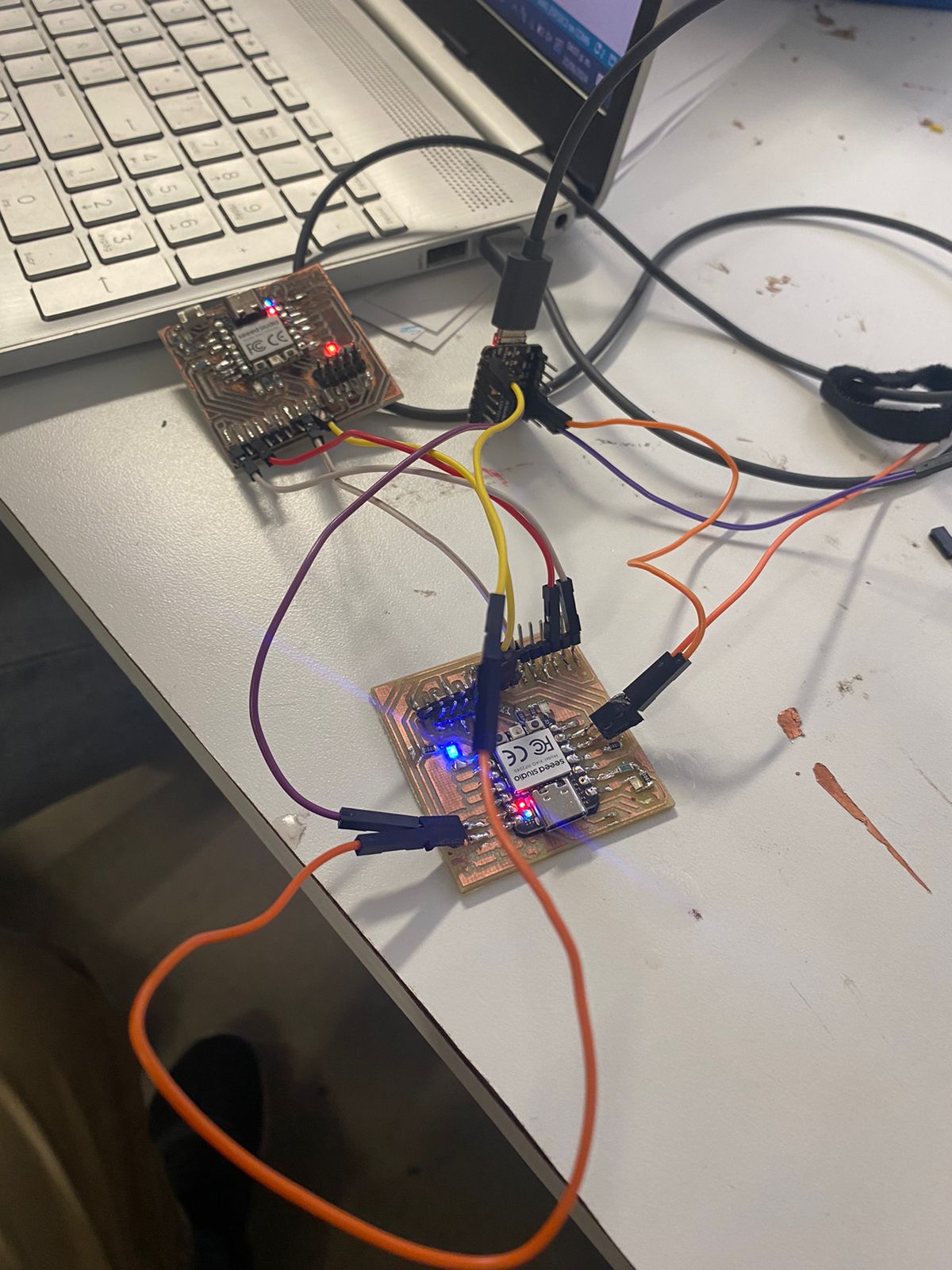
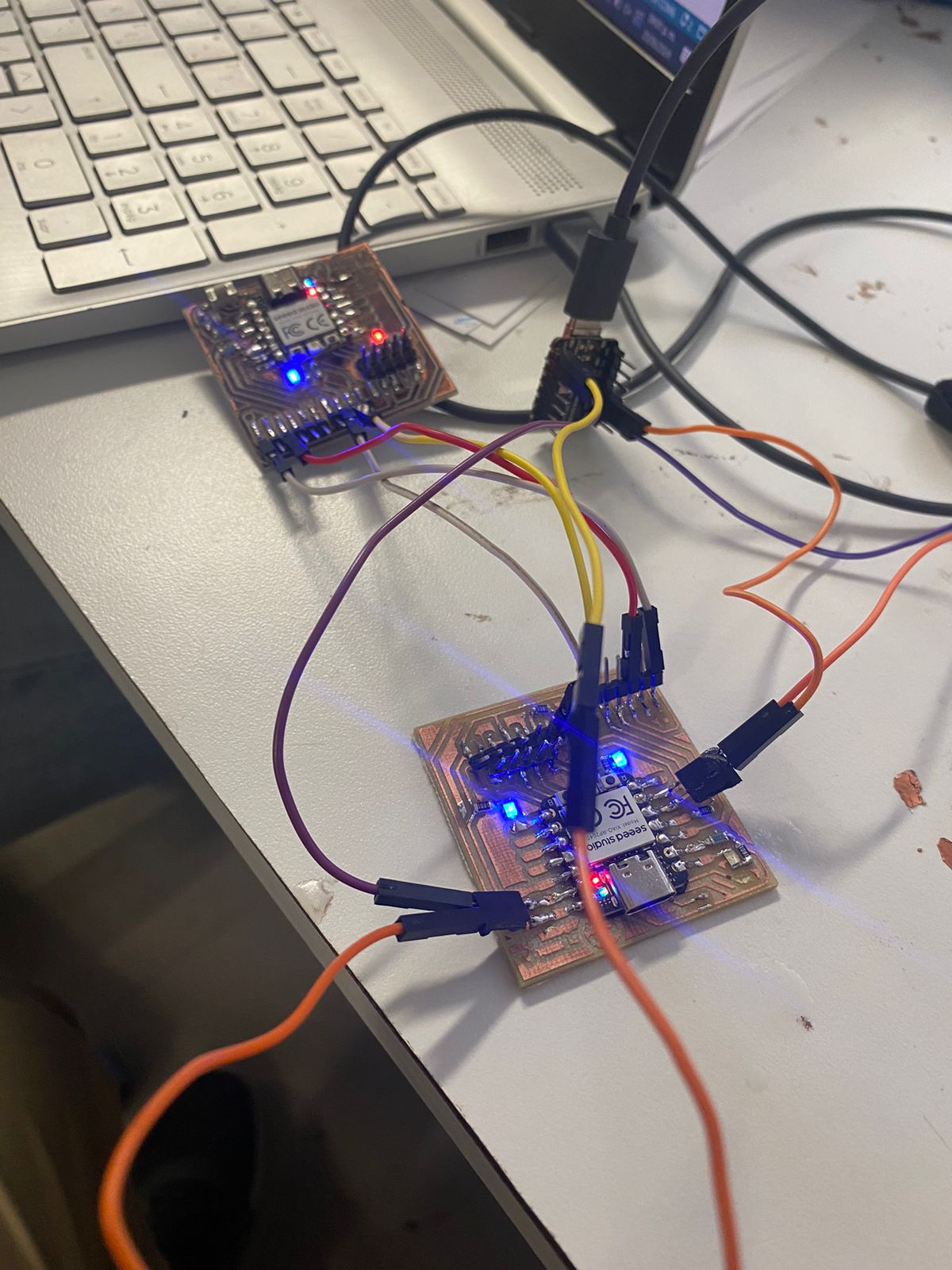
result
In the first image i inputed the command to make the tx led to shine by pressing T and on the second I pressed R to light the second led


