8. Electronic Design
THIS WEEK GROUP ASSIGNMENT(click the title)
Idea
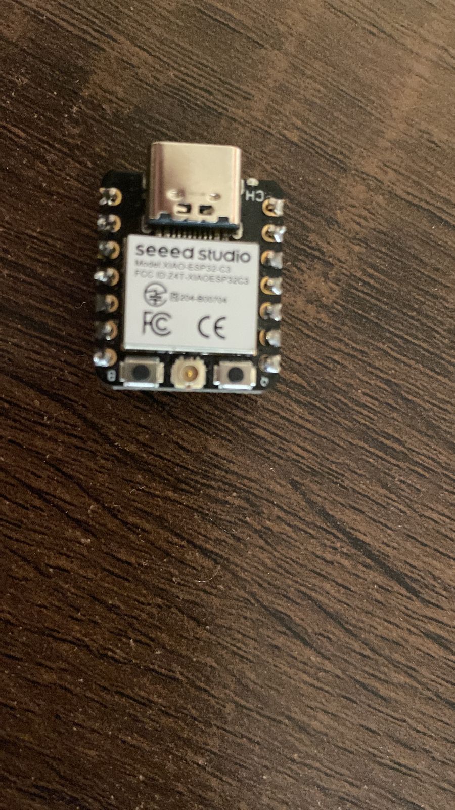
I wanted to try to work with neopixels so i designed a PCB that would connect the neopixels with a xiao SP 32c3
KICAD
KiCad is an open source software suite for Electronic Design Automation (EDA). The programs handle Schematic Capture, and PCB Layout with Gerber and IPC-2581 output. The suite runs on Windows, Linux and macOS and is licensed under GNU GPL v3.
PCB Design Process
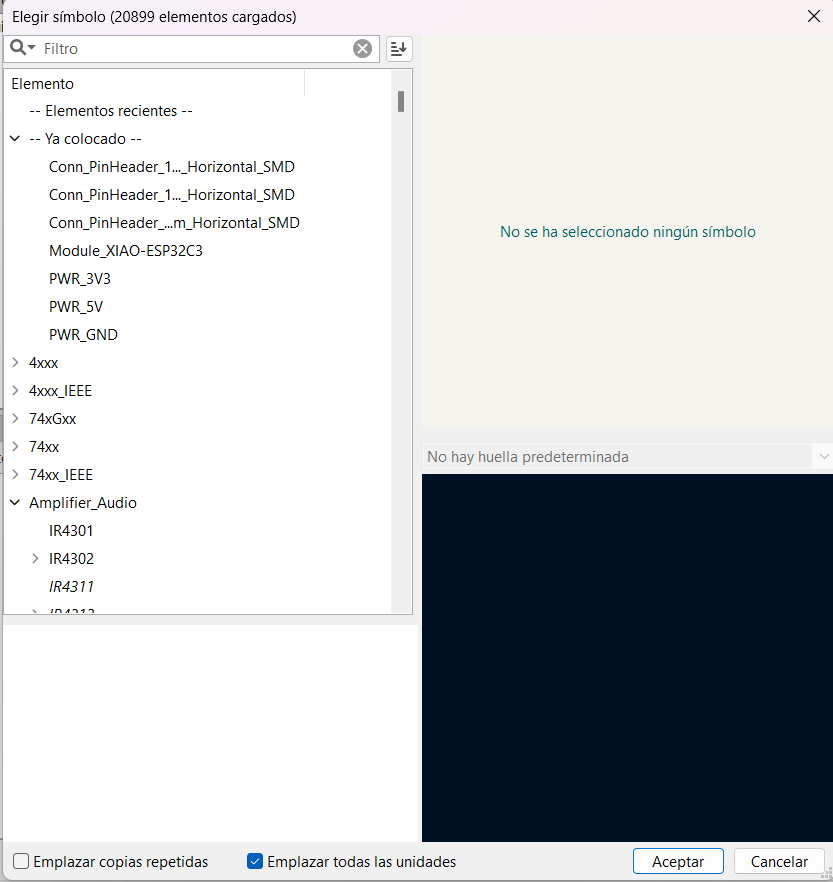
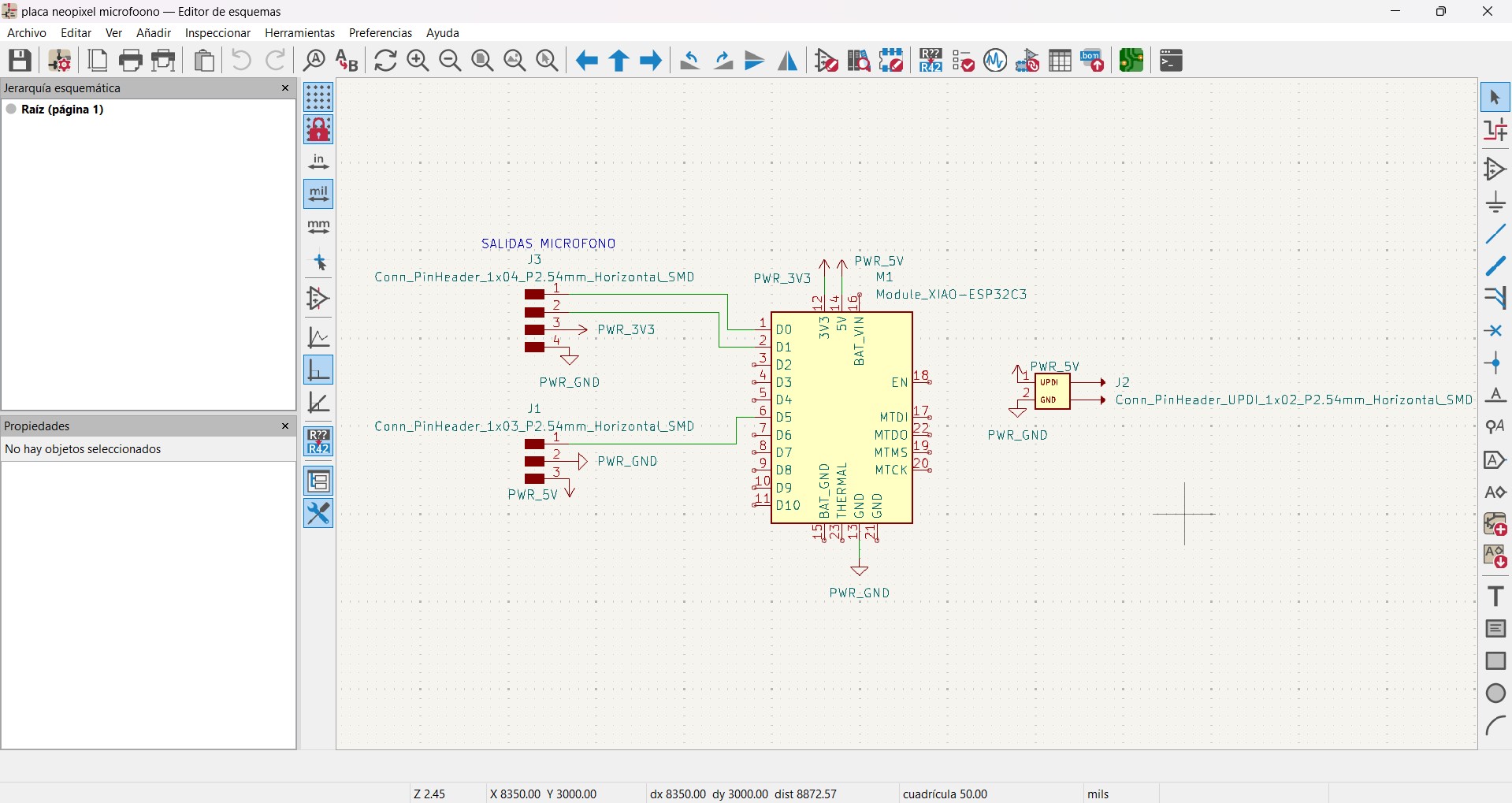
- Schematic Design: I started by creating a schematic in KiCad, where I placed the components (Neopixel LED strip and sound sensor) and connected them using appropriate symbols and wiring.
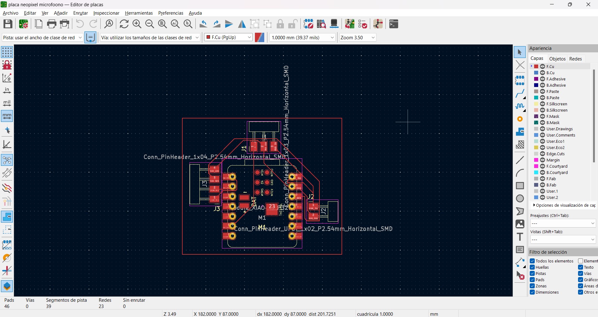
- Component Placement: After finalizing the schematic, I moved on to placing the components on the PCB layout. I ensured adequate spacing and alignment for easy soldering and optimal signal routing.
- Routing Connections: Using KiCad's routing tools, I carefully connected the pins of the Neopixel LED strip and the sound sensor to the appropriate pads and traces on the PCB. I paid attention to signal integrity and avoided crossing traces where possible to minimize interference.
- Design Validation: Once routing was complete, I performed a design rule check (DRC) to ensure there were no errors such as unconnected nets, overlapping pads, or clearance violations.
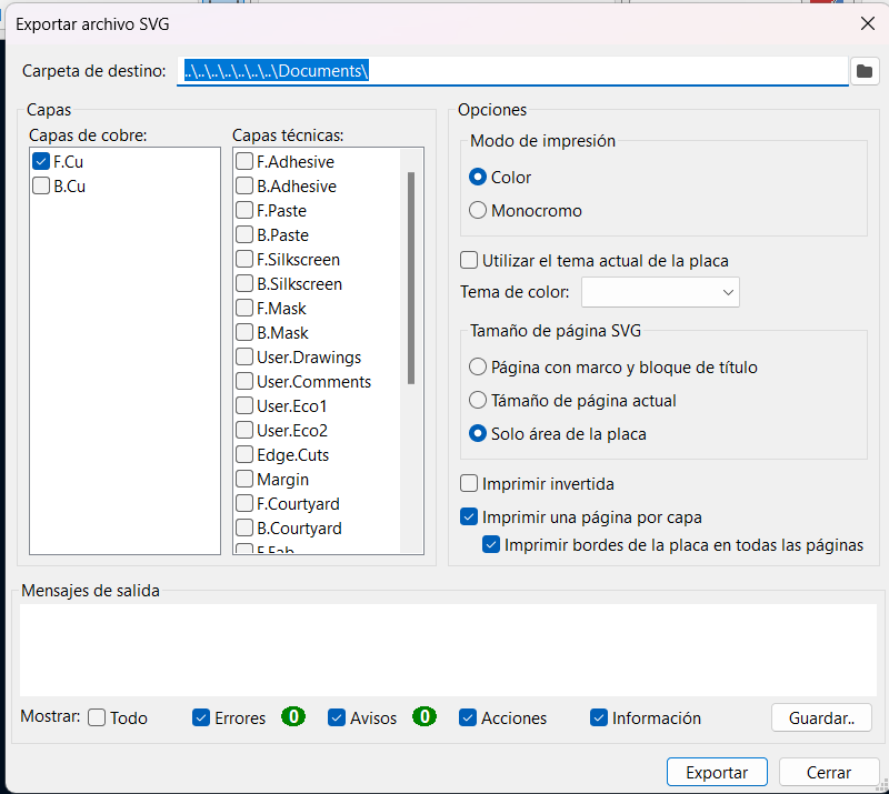
- Generating Gerber Files: After validating the design, I generated Gerber files, which are industry-standard files used for PCB fabrication. These files include all necessary information for manufacturing the PCB.
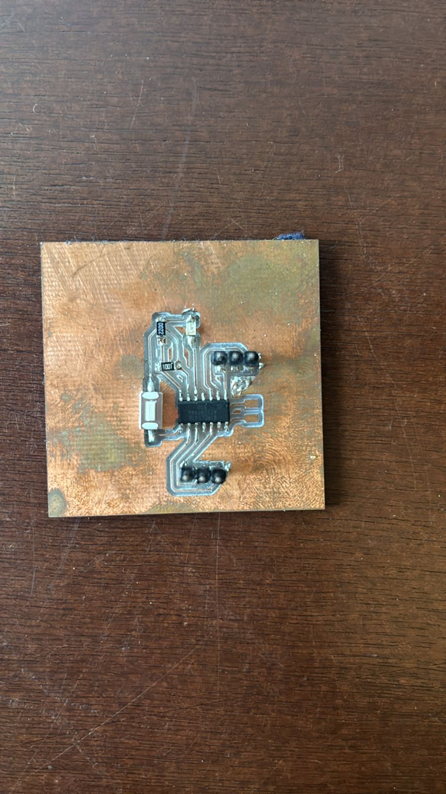
- Review and Fabrication: Before sending the Gerber files for fabrication, I reviewed the design once more to confirm correctness. Then, I got them produced and salodered teh components


I designed the xiao to not be connected in the remaining ports as i had no use for them.
After having cut the pcb I soldered cables to mi neopixels and then conected the cables to the pins conected to the xiao respectively
test Code (result of code in output week)
					#include

					#define PIN_NEOPIXELS    2  // Pin al que están conectados los Neopixels
					#define NUM_NEOPIXELS    8  // Número de Neopixels conectados

					Adafruit_NeoPixel pixels = Adafruit_NeoPixel(NUM_NEOPIXELS, PIN_NEOPIXELS, NEO_GRB + NEO_KHZ800);

					void setup() {
					  pixels.begin(); // Inicializa la comunicación con los Neopixels
					}

					void loop() {
					  // Enciende los Neopixels en un color específico (verde)
					  colorWipe(pixels.Color(0, 255, 0), 50); // Cambia el color y el brillo según lo desees

					}
					void colorWipe(uint32_t color, int wait) {
					  for(int i=0; i < pixels.numPixels(); i++) {
						pixels.setPixelColor(i, color);
						pixels.show();
						delay(wait);
					  }
					}