4. Electronic Production
This week i worked on the PCB that our instructor designed for us so we could cut it and solder it ourselves.
THIS WEEK GROUP ASSIGNMENT(click the title)
What is MODS?
MODS is an app which converts and image to an rml file

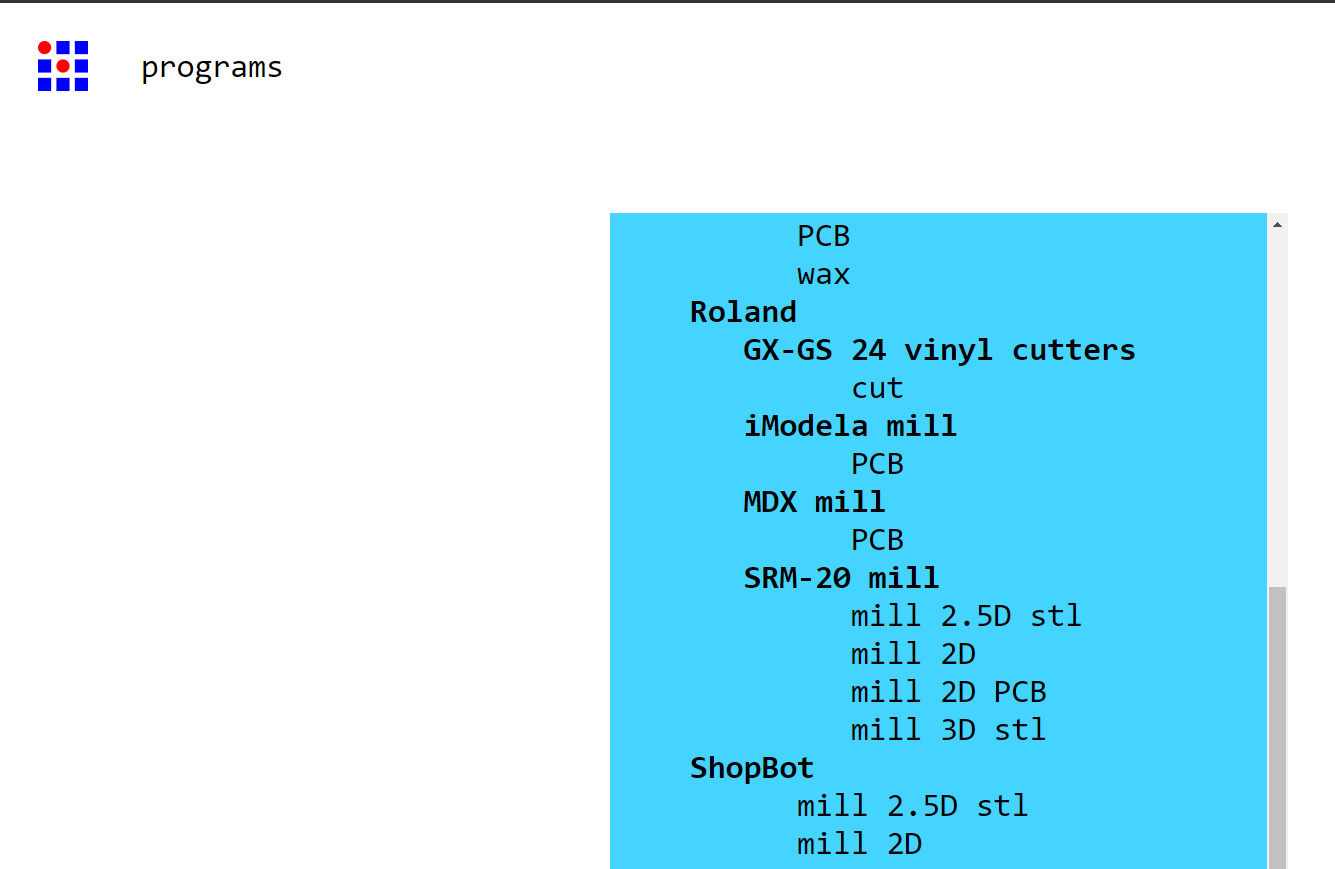
To use it you enter the page then right click which opens a window in which you select progrmas and search for Roland and select SRM-20 mill and 2D mill PCB
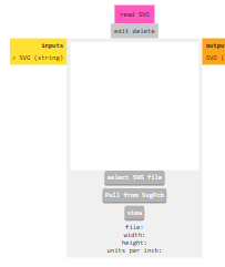
It will open a window where you need to upload the image of your PCB and once uploaded you invert the colors in the slide to the right of the one where you upload your image.
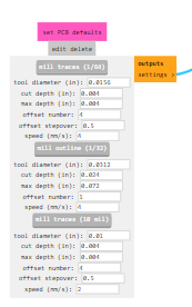
Then you serach the slide that says "set PCB defaults" and for the traces you select the 1/64 option and when your doing the outline you select the 1/32 option.
Then you go to the slide called "Roland SRM-20 milling machine" and set the origin to 0 on x,y and z. Then go to the right and turn on the button that was off.
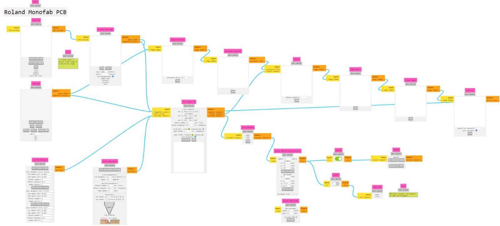
To finish you press "calculate" in the slide called "mill raster 2D" and it will give you the file ready to be cut.
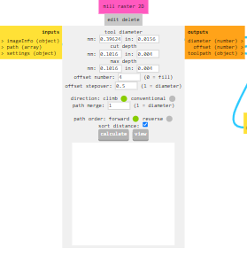
What program will we use to cut
Where going to use Vpanel for SRM-20, which is the controller for the Roland SRM-20
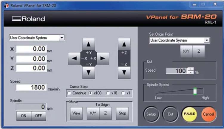
the program only starts once you have conected your computer with the roland once it is up you move the tool to the place you want your oringin to be, being careful not to break the tip while moving the z axis, and set your origin. Then you upload your .rml file by clicking the setup button and press start to mill your PCB
Soldering
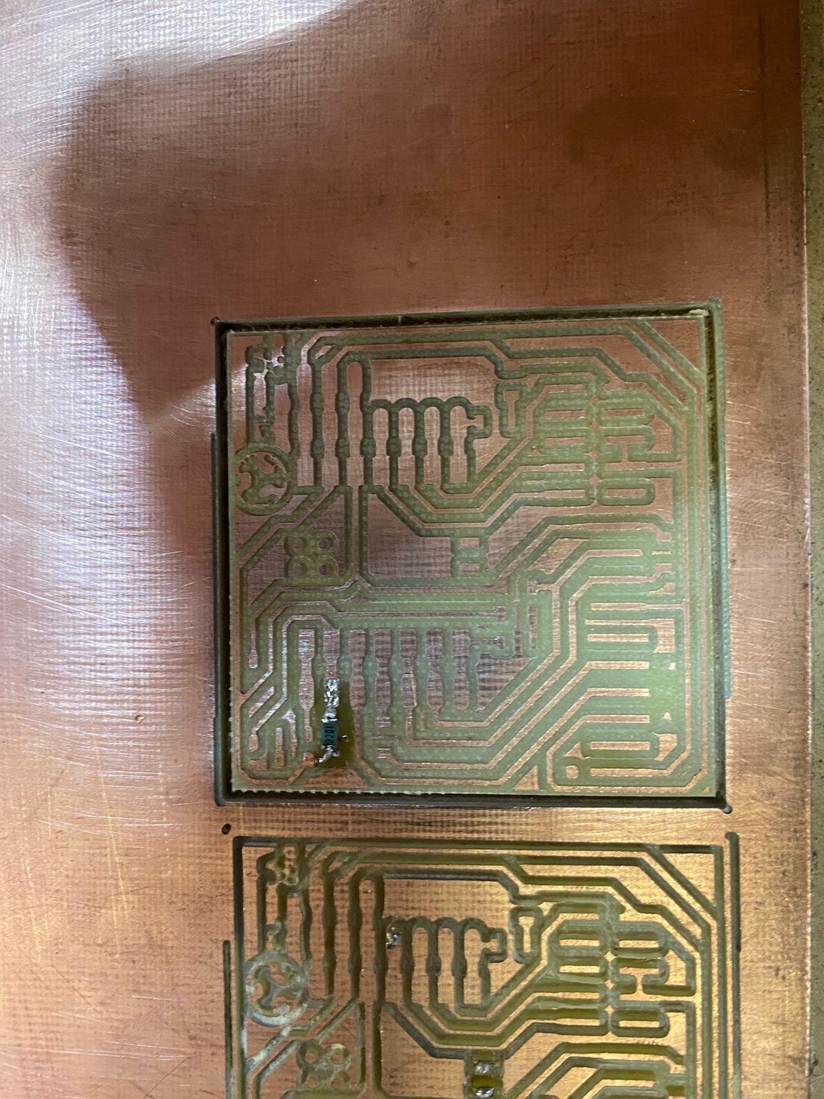
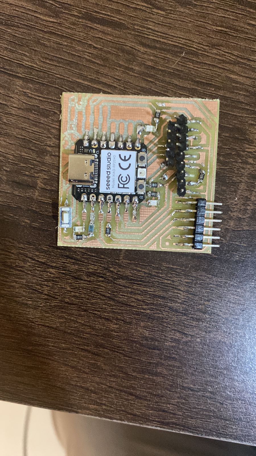
Before soldering I recomend to give your PCB a light sanding to remove dust and copper thar might have been stuck in the milling. After the sanding i satrted soldering where i learned that to solder a resistance and a led its not very dificult but to solder pins its complicated unless you drill a hole for the legs of the pin
Programming
I used this code in Arduino to turn on the leds
// Definición de pines const int ledPin = 13; const int buttonPin = 2; bool ledState = LOW; // Estado inicial del LED (apagado) void setup() { pinMode(ledPin, OUTPUT); // Configura el pin del LED como salida pinMode(buttonPin, INPUT_PULLUP); // Configura el pin del botón como entrada con pull-up interno } void loop() { // Verifica si se presionó el botón (debido a la configuración de PULL_UP, está activo bajo) if (digitalRead(buttonPin) == LOW) { // Invierte el estado actual del LED ledState = !ledState; digitalWrite(ledPin, ledState); // Enciende o apaga el LED según el estado actual delay(200); // Espera breve para evitar rebotes del botón } }
Conclusion
Its not dificult to use the MODS program to create the rml file and its not dificult to solder the componets but bot take time to get right the first time and some tiny components are realy easily moved around so gotta be careful when soldering them and to program it its a little bit more dificult since i didnt understand some parts of how it works.
