3D SCANNING AND PRINTING
Group assignments
The main objective of this week is to be able to recognize the codes in the basic operation that will be carried out. What is the heat-based layer adhesion process? The machines will be used to print in 3D and we will use a PLA type filament.
3D printing operates on the fundamental principle of transforming a digital model into a tangible three-dimensional object by progressively depositing material layer by layer.
This method of manufacturing differs significantly from traditional subtractive techniques such as CNC machining or formative methods like injection molding.
In contrast to these methods, 3D printing does not require additional tools for cutting or shaping. Instead, the piece is built directly onto a platform, gradually constructed layer by layer. This characteristic grants us the ability to produce intricately complex parts efficiently and flexibly.
In order to 3D print a part, it's crucial to first design the 3D model using CAD software. After that, the file is uploaded to the printer software, which slices the model into thin two-dimensional layers. These layers are then converted into a set of machine-readable instructions (G-code) for the printer to execute. This process ensures the accurate reproduction of the model in physical form.
- Here are the main 3D printing technologies we've been exploring:
- Stereolithography (SLA):Think of it as wielding a magical light wand to transform liquid plastic into fascinating shapes. A UV laser meticulously solidifies liquid resin in a tank, layer by layer, until your creation emerges. It's perfect for intricate designs and sleek finishes.
- Laser Sintering (SLS): Picture sprinkling a fine layer of powder and then using a laser to fuse it into a solid object. That's the essence of SLS. It intricately builds objects by melting powder together layer by layer, allowing for complex structures without the need for additional support.
- Fused Deposition Modeling (FDM): This one's akin to a hot glue gun on overdrive. It heats up plastic filaments, extruding them to stack layers and form your desired object. It's the go-to method, incredibly versatile, and ideal for both prototyping and functional components.
- Digital Light Process (DLP): DLP operates similarly to SLA but with a twist. Instead of a laser, it employs a digital light projector to flash a single image of each layer at once. This speeds up the process significantly by curing entire layers simultaneously.
- Multi Jet Fusion (MJF): MJF lays down a layer of powder and then sprays it with a binding agent activated by infrared light. This technique yields finely detailed and robust parts, making it suitable for both prototypes and finished products.
- PolyJet: Think of it as a top-tier inkjet printer but for 3D printing. It jets tiny droplets of photopolymer, instantly cured by UV light. With PolyJet, you can achieve remarkable detail and even blend different materials for diverse properties and colors within a single print.
- Direct Metal Laser Sintering (DMLS): DMLS, the metal aficionado's choice, operates similarly to SLS but with metal powder. A laser meticulously fuses metal powder layer by layer, perfect for crafting high-strength, intricate parts and prototypes sans molds.
- Electron Beam Melting (EBM): EBM harnesses the power of—you guessed it—an electron beam to meld metal powder together, layer by layer, within a high-vacuum environment. This method excels in producing durable, stress-resistant parts, particularly in aerospace and medical applications.
| PROS✅ | CONTRAS🚫 |
|---|---|
| Geometric complexity at no additional cost. | Material properties that exhibit anisotropic behavior and lower strength. |
| Very low initial costs. | Less competitive in costs at higher volumes. |
| Customization of each and every component. | Limited precision and tolerances. |
| Low-cost prototyping with very fast delivery times. | Support removal and post-processing elimination. |
| Wide range of (specialized) materials available. |
Here's how it operates: a filament reel is loaded into the printer and then fed to the extrusion head, equipped with a heated nozzle. Once the nozzle reaches the desired temperature, a motor drives the filament through it, melting it.
The printer moves the extrusion head, depositing the molten material in precise locations, where it cools and solidifies (similar to a highly precise hot glue gun).
When one layer is completed, the build platform descends, and the process repeats until the piece is finished.
Following printing, the piece is typically ready for use, although it may require some post-processing, such as support structure removal or surface smoothing.
The plastics used in 3D printing are lightweight materials with a wide range of physical properties, suitable for both prototyping purposes and some functional applications. Below, I list some of these materials.
| Materials | Description |
|---|---|
| High rigidity, good detail, cost-effective. PLA is a biodegradable thermoplastic suitable for low-cost, non-functional prototyping. It offers finer detail than ABS but is more brittle and not suitable for high temperatures. | |
| Basic plastic with improved mechanical and thermal properties compared to PLA. ABS is a common thermoplastic with good mechanical properties and excellent impact resistance, superior to PLA but with less defined details. | |
| High detail and smooth surface, yielding prototypes akin to injection moldings. Resins are thermosetting photopolymers that solidify upon exposure to light, producing highly detailed parts with a smooth surface finish resembling that of an injection mold. | |
| Used to replace injection molded functional parts, with good chemical resistance. Nylon or polyamide (PA) is a thermoplastic with excellent mechanical properties, high chemical resistance, and abrasion resistance, perfect for functional applications. | |
| Suitable for mechanical parts with high impact resistance and flexibility. Sterilizable. PETG is a thermoplastic with improved properties over PLA, offering high impact resistance and excellent chemical and moisture resistance. PETG can be sterilized. | |
| Rubber-like material suitable for tubes, grips, seals, and gaskets. TPU is a thermoplastic elastomer with low Shore hardness and a rubber-like feel that can be easily flexed and compressed. | |
| UV stability and high chemical resistance, preferred material for outdoor applications. ASA is a thermoplastic with properties similar to ABS but with improved thermal, chemical, and weather resistance, perfect for outdoor applications. | Engineering plastic for high-performance applications, flame retardant. PEI is an engineering thermoplastic with good mechanical properties and exceptional heat, chemical, and flame resistance. |
For this practice, I decided to use the Ender v3 printer located in the Fab Puebla labs. These are the workhorses of the 3D printing world. Popular for their affordability and reliability, Ender 3 printers are great for beginners and pros alike. They're versatile, easy to use, and perfect for a wide range of printing projects.
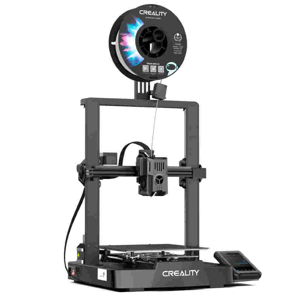
ENDER 3 S1 PRO
- Printing Technology: FDM
- Build Volume: 220 x 220 x 270 mm
- Printing Speed: 150 mm/s
- XY resolution: ± 0.1 mm
- Layer Height: 0.05 - 0.4 mm
- Nozzle Temperature: Up to 300° C
- Supported Materials: PLA, ABS, PETG, TPU, PA, WOOD
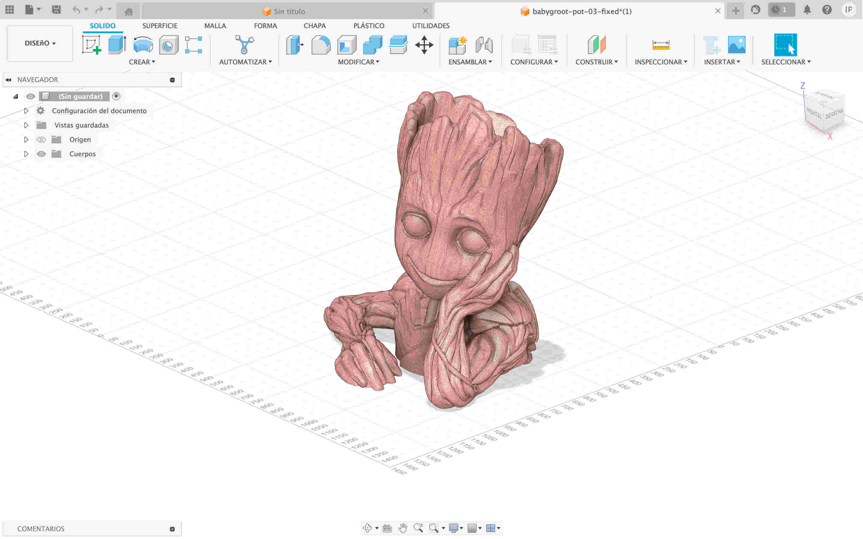
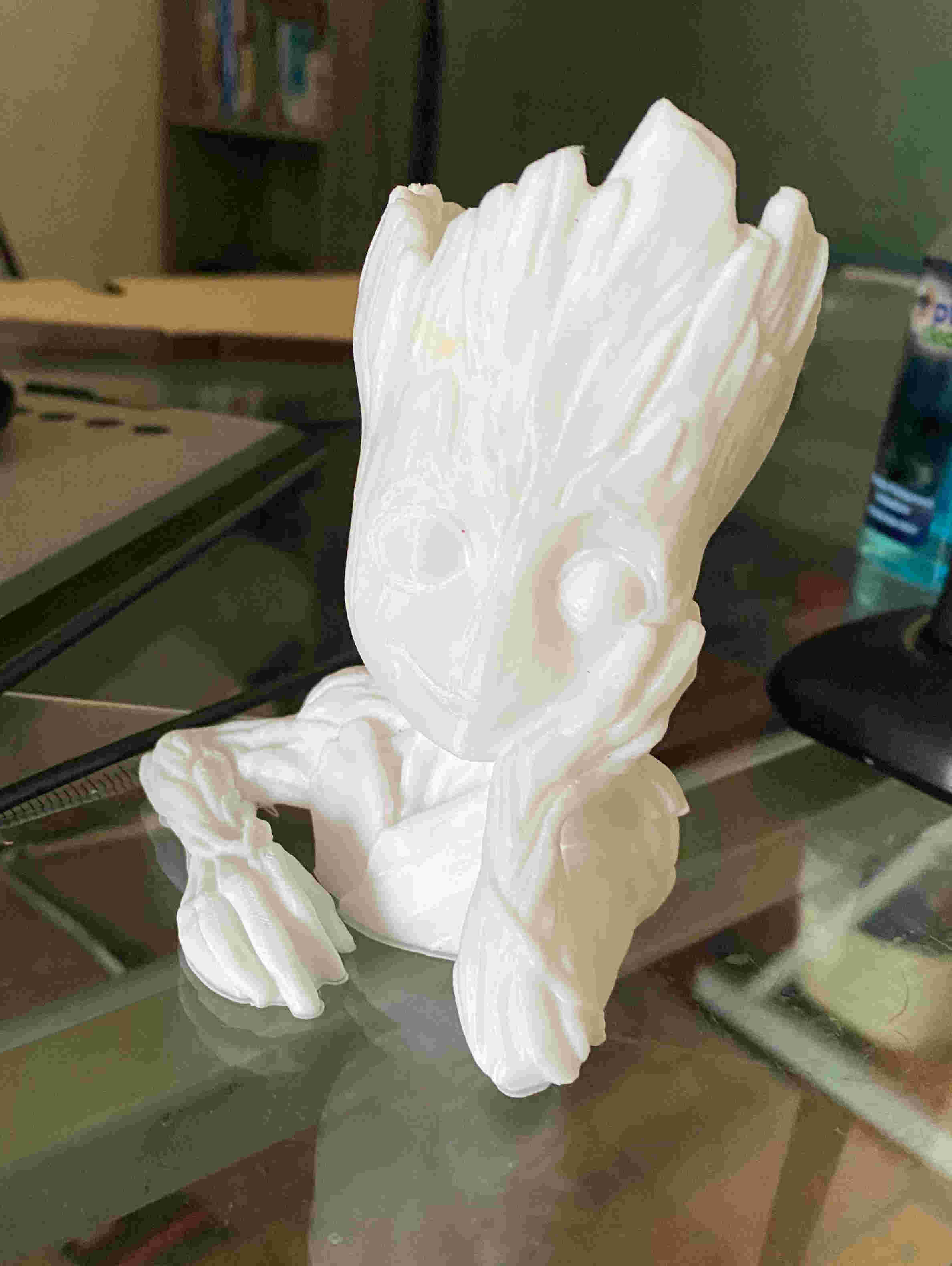
I'm GROOT
For this week I decided to download a baby groot so I could see how 3D printing worked
How make my file in ultimate Kura
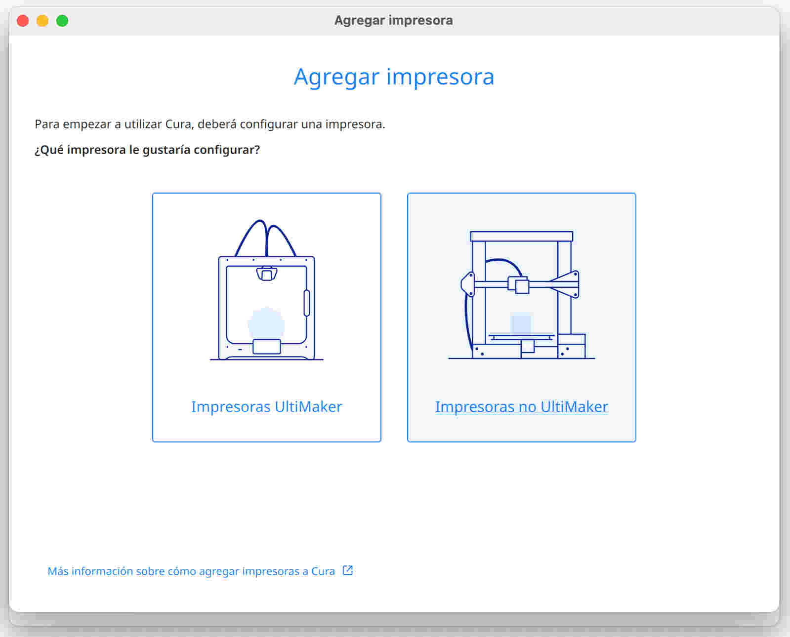
- So that the first step is to configure the machine, you must go to preferences (in the top bar) > configure UltimakerCura. A tab will be displayed that will say printers and we click on the add button and look for the machine to which we will link, which will be " ".


- If you can't find the machine model, you can choose "Custom FDM Printer".

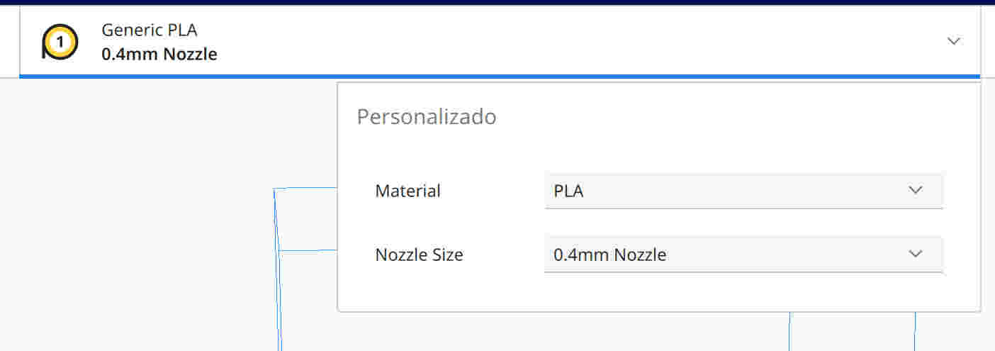
- Place in the characteristics of the machines the dimensions and thickness of the material to be printed and the diameter of the nozzle will be placed, in my case it is .4 mm
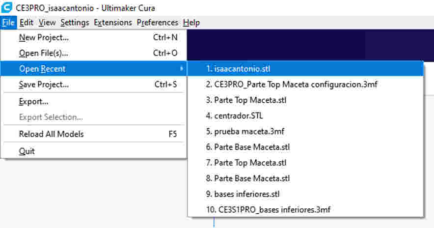
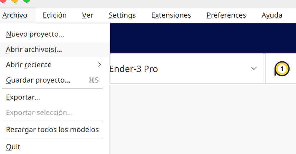
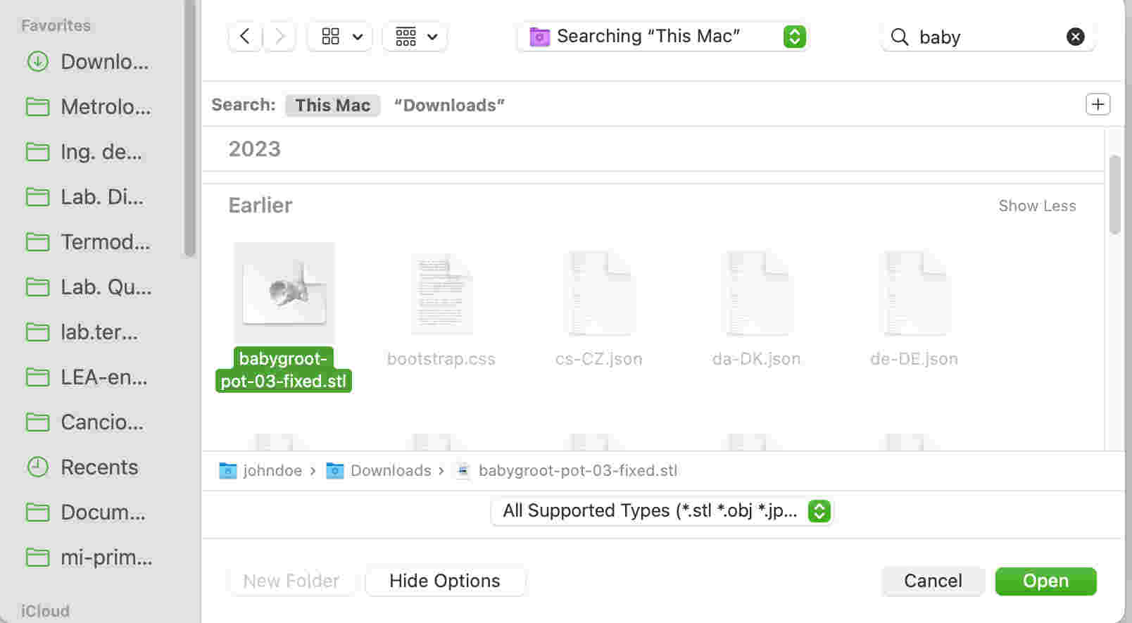
- To be able to import the file in STL, from the toolbar, click "file" and open the desired file. One tip is to do it directly from the drag option from the search engine to the program interface to be faster.
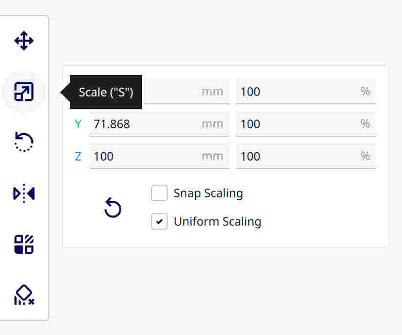
- On the left side of the interface you can see tools to modify and move the 3D model. The first will allow us to drag the object freely along the axes and the second will allow us to scale the 3D model uniformly and the object can be rotated freely or uniformly.

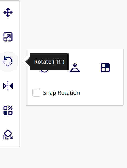
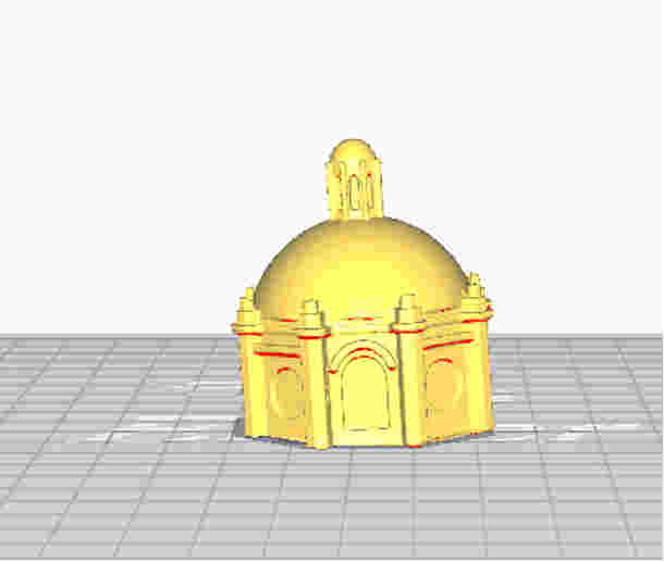
- In the rotating the object part there is an option where we can choose which part of the figure we want the view to print on the 3D printing platform.

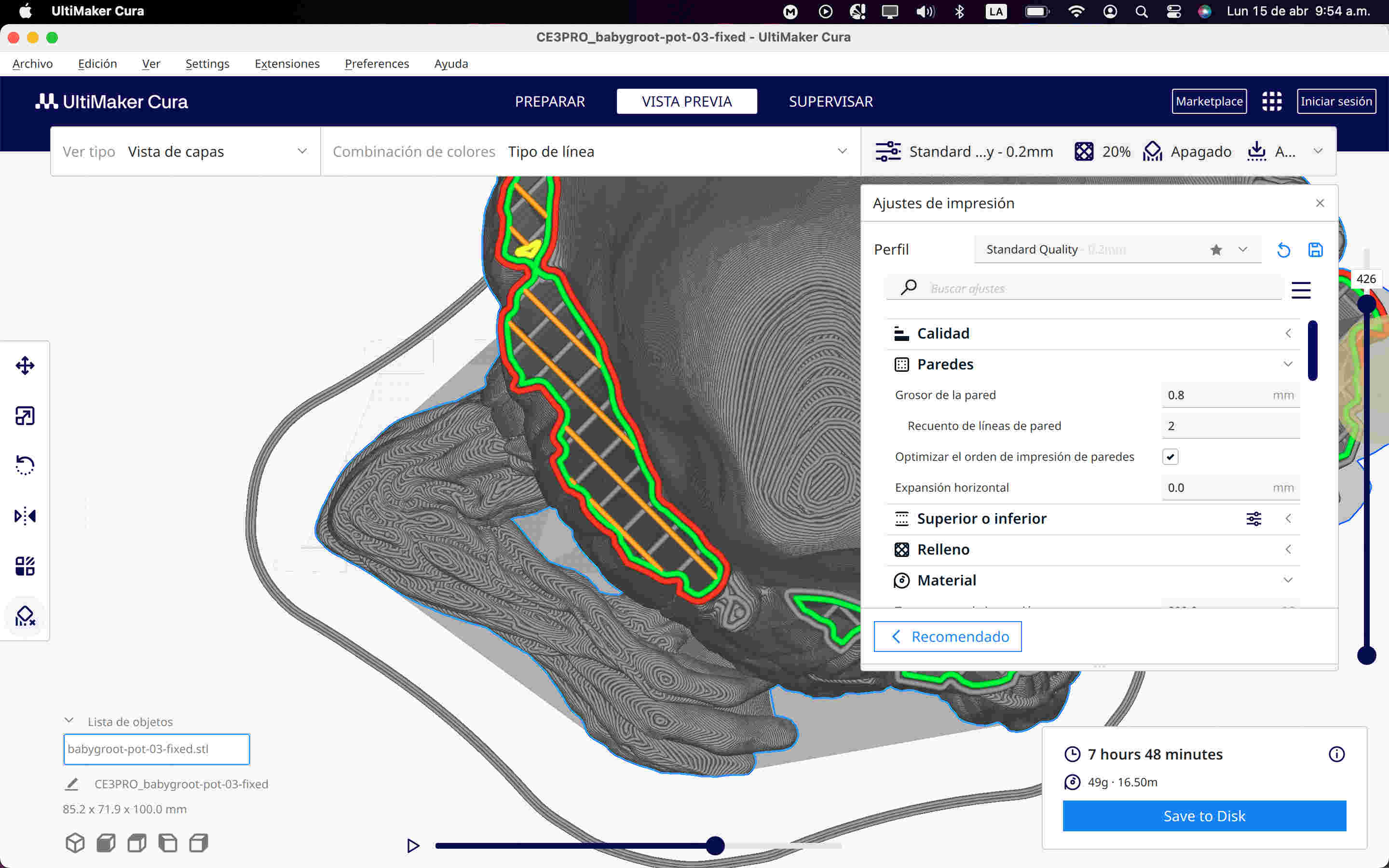
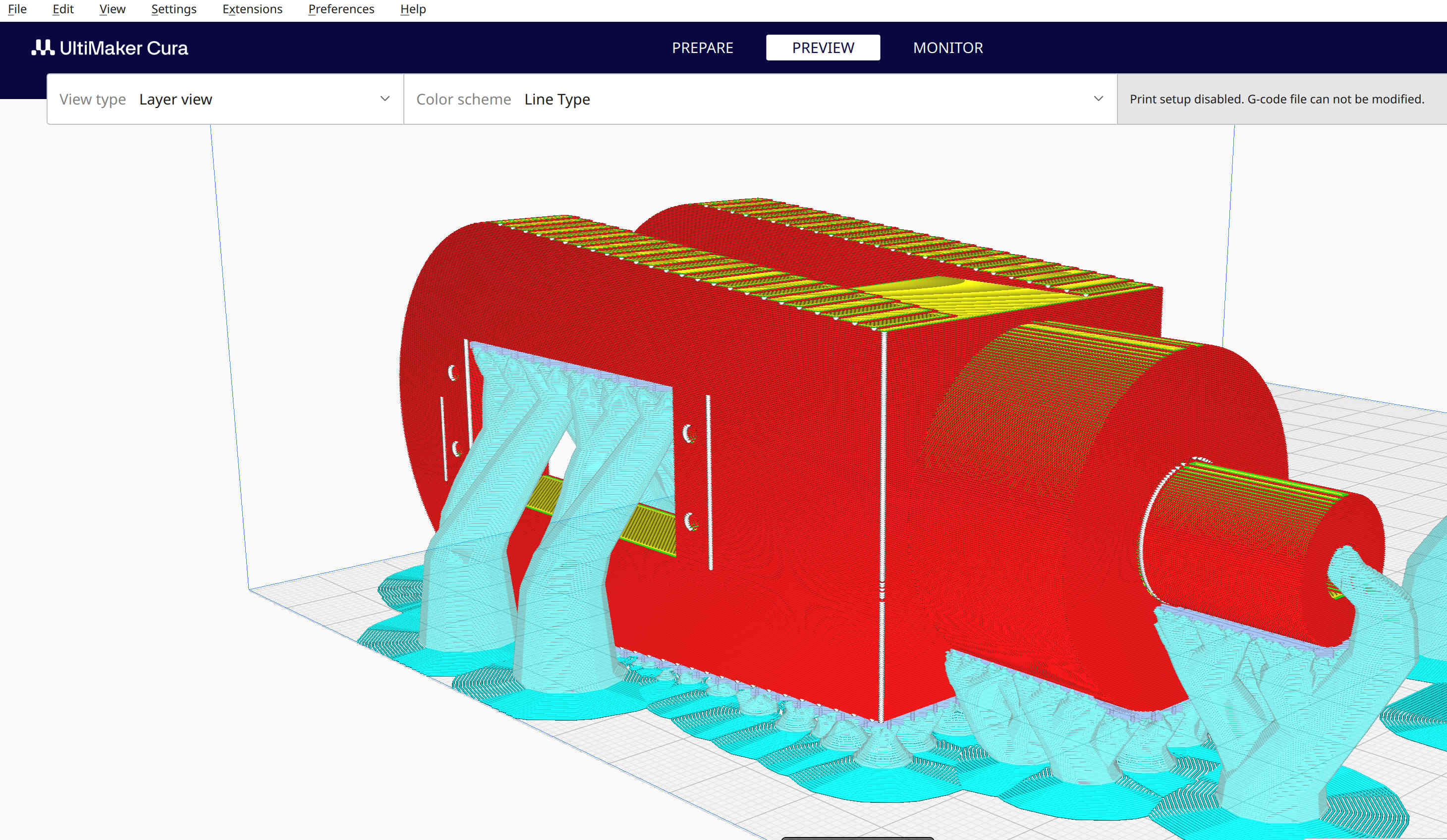
- At the top is the preview option in which we can see the options that the interface offers us to see how our 3D model is going to be printed, and we will give the preferences depending on how we see how we want the printing process to be. Printing (this will affect the extended time)

- While in the preview I can move the layer construction line to view a specific layer or area desired. In the bottom bar I can see the extruder passage.

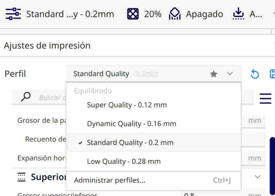
- By selecting the quality button, I can see the preferences that I can modify for 3D printing. In the profiles part, the quality options offered by the program are displayed. In this example, I will start with the "Standard Quality-0.2mm" option, which is the average.
- In the "Quality" option, I have as important options "the height of the layer" and "the initial height of the layer", both managing 0.2 since it is 50% of the diameter of the nozzle. As for the layer height, it is advisable for me, when starting to experiment, to start from the middle and then adjust it within a smaller range (0.16-0.12-0.08) to obtain a finer finish, although this will lengthen the time of impression. On the contrary, if I choose larger ranges (0.24-0.28), the printing time will decrease, but the quality will be affected.
It is important to also consider the initial height of the layer, as it could cause detachment if it is not adequate, so 50% of the nozzle diameter is recommended.

- As for the "Walls", these walls are limitingly located on the external and internal part of my model. I start with a base of 1 to 2 lines, in this case I experimented with 2 and 3 lines. In case I need a strong structure, such as in the case of gears, I use more than 4 lines.

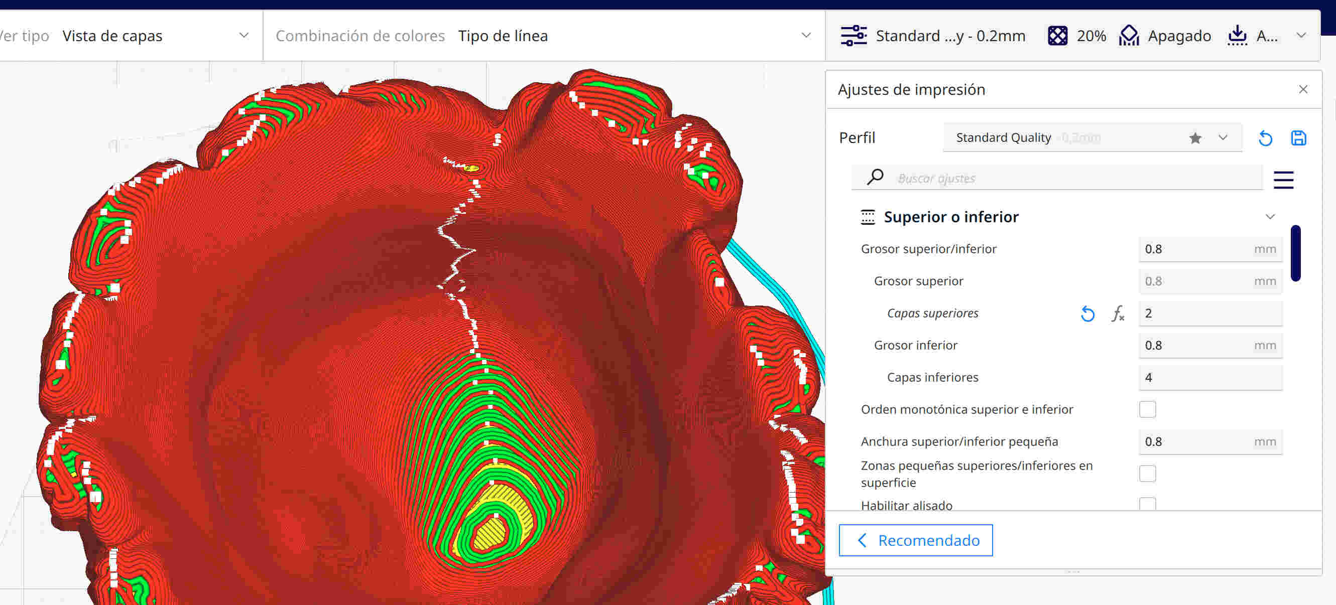
- The "Upper Layers" are these walls that are found limitingly on the outside and inside of my model. But unlike the previous one, only the upper and lower layers are defined in this layer. In this case, I experimented with 2 lines for the top and 4 lines for the bottom, and also with 3 lines for the top and 4 lines for the bottom. Fewer lines can create gaps.

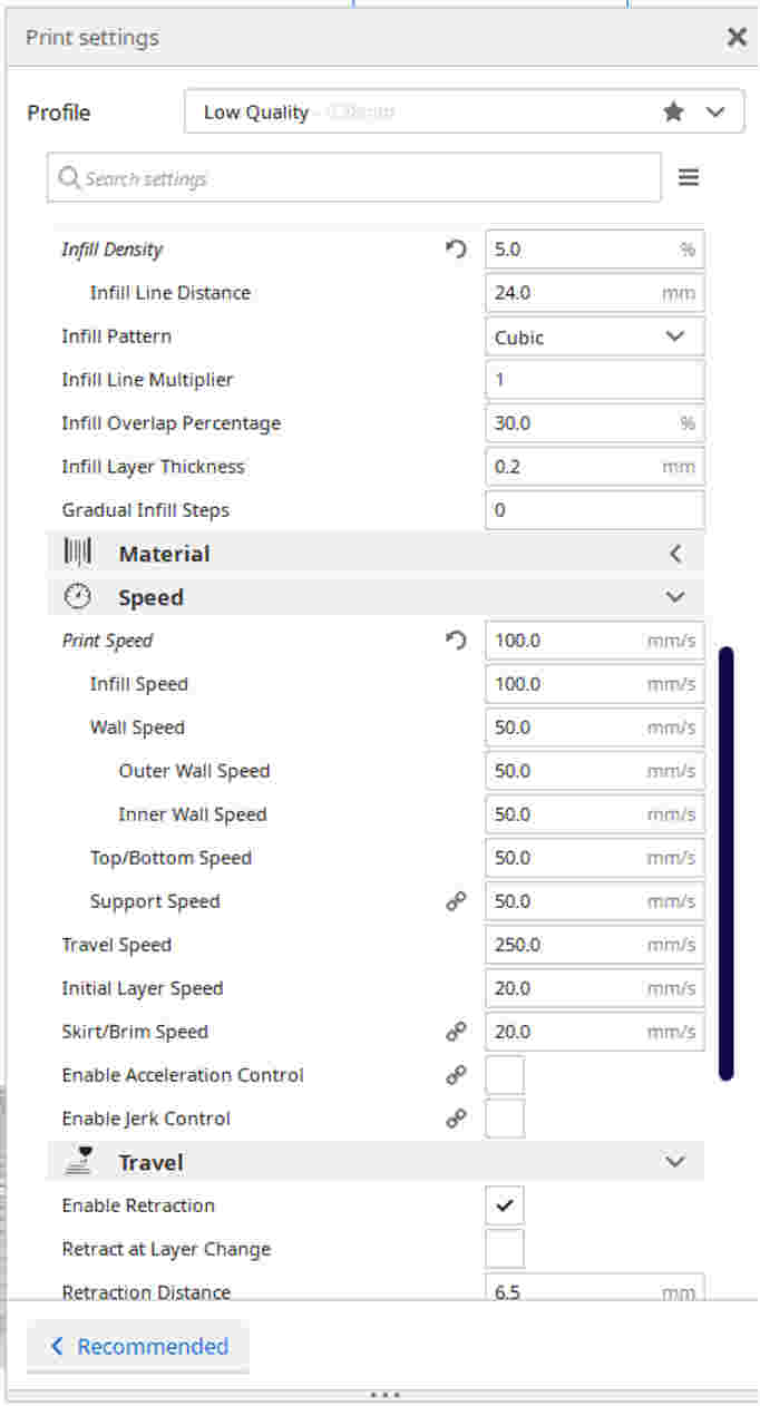
- In the "Fill Density" option, I can adjust the fill of my model. I can change the dimensions and shape of this to support the model without increasing print time.

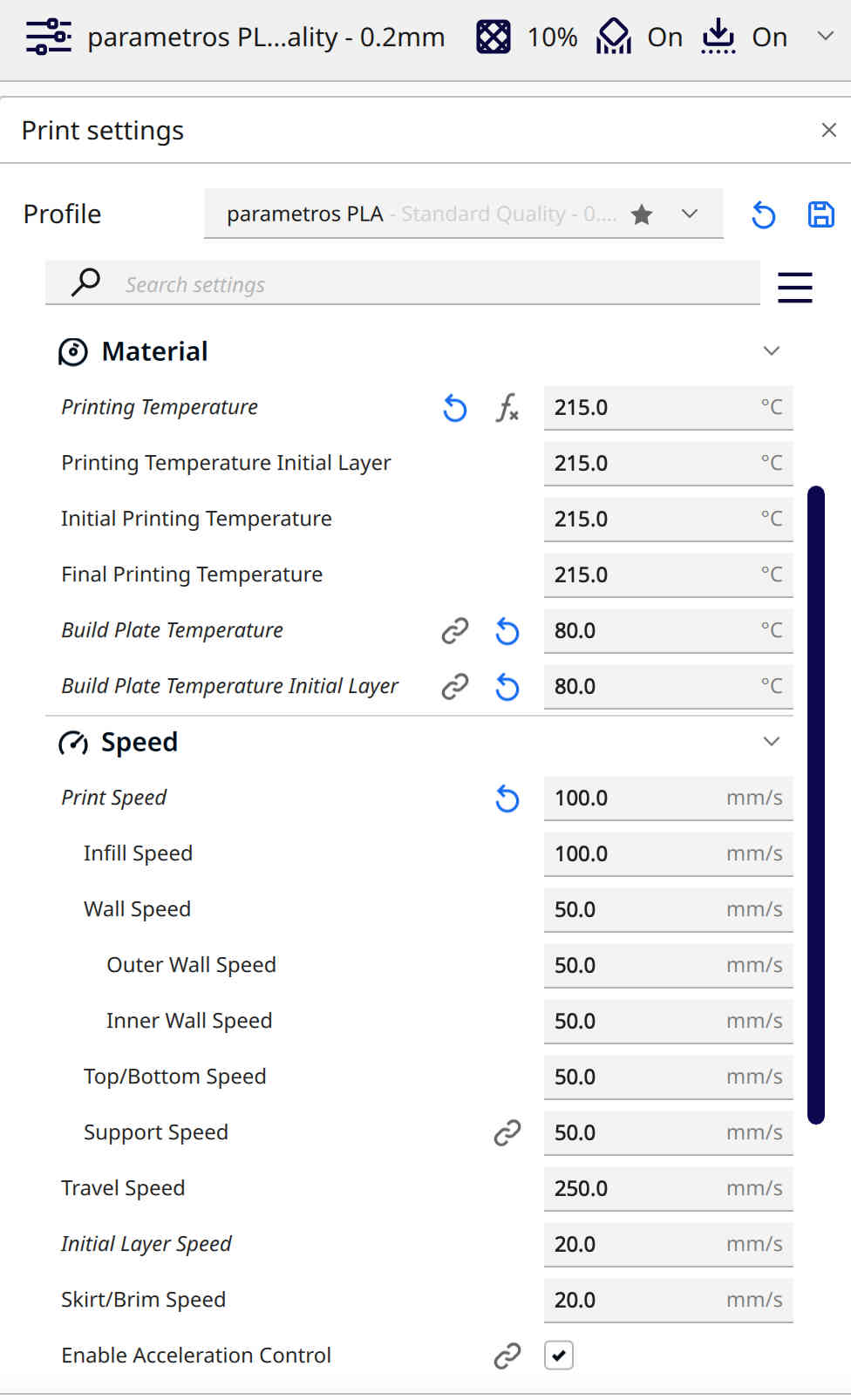
- In the "Speed" option, I chose to use the maximum recommended speed, which is 85 mm/s, for better results in print time. However, I decided to use a slower speed of 20mm/s on my initial layer to prevent it from peeling off the surface of the machine.

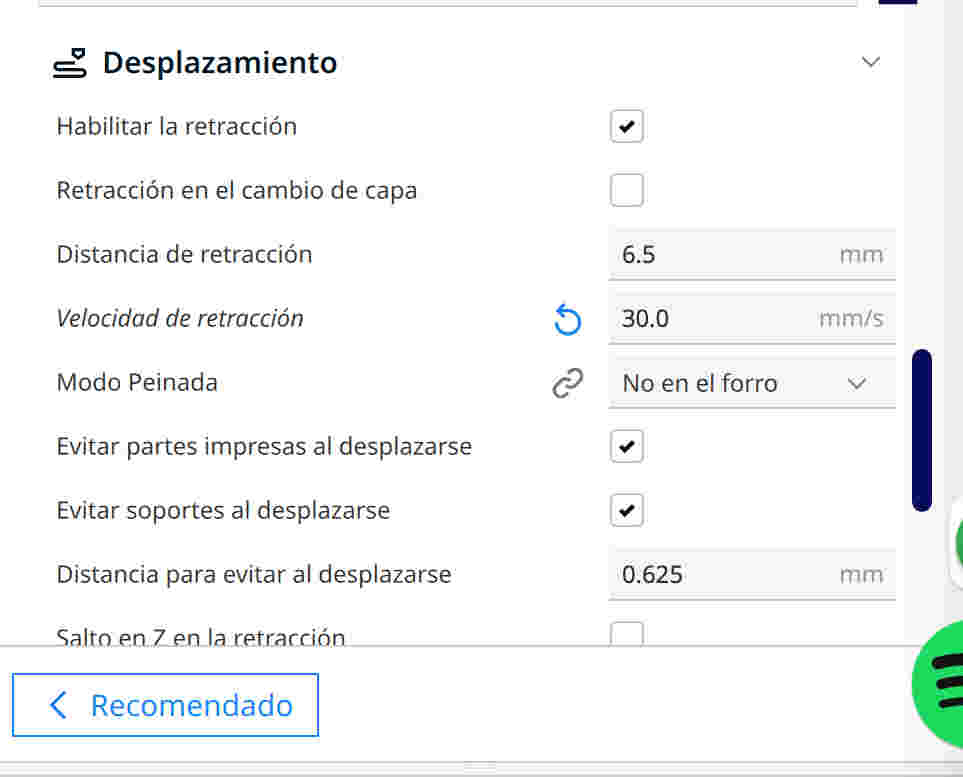
- “Retraction distance”, this “base” recommended offset to remove threads.
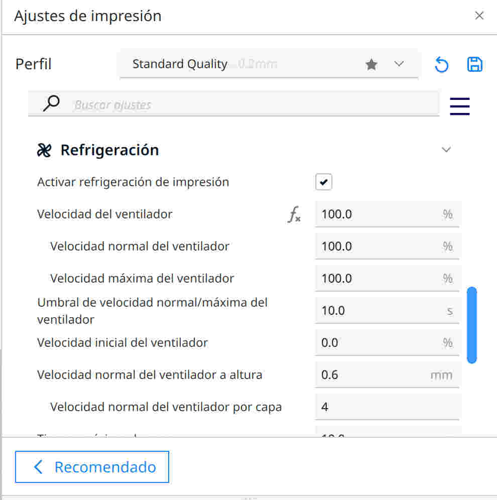
- As for "Cooling", I made sure it was on and pointed at the nozzle. In case of printing ABS, I decided to experiment by disabling it due to the melting point of the plastic.
- "Support", here I have two types available: one straight and one tree. Both have different benefits. It is important for me to consider the overhangs of my design when choosing the appropriate support type and angle of inclination.

- Regarding "Adhesion to the printing plate", I chose to use excess material to improve stability. However, in many cases, it is not necessary as it can increase my printing time without needing it.
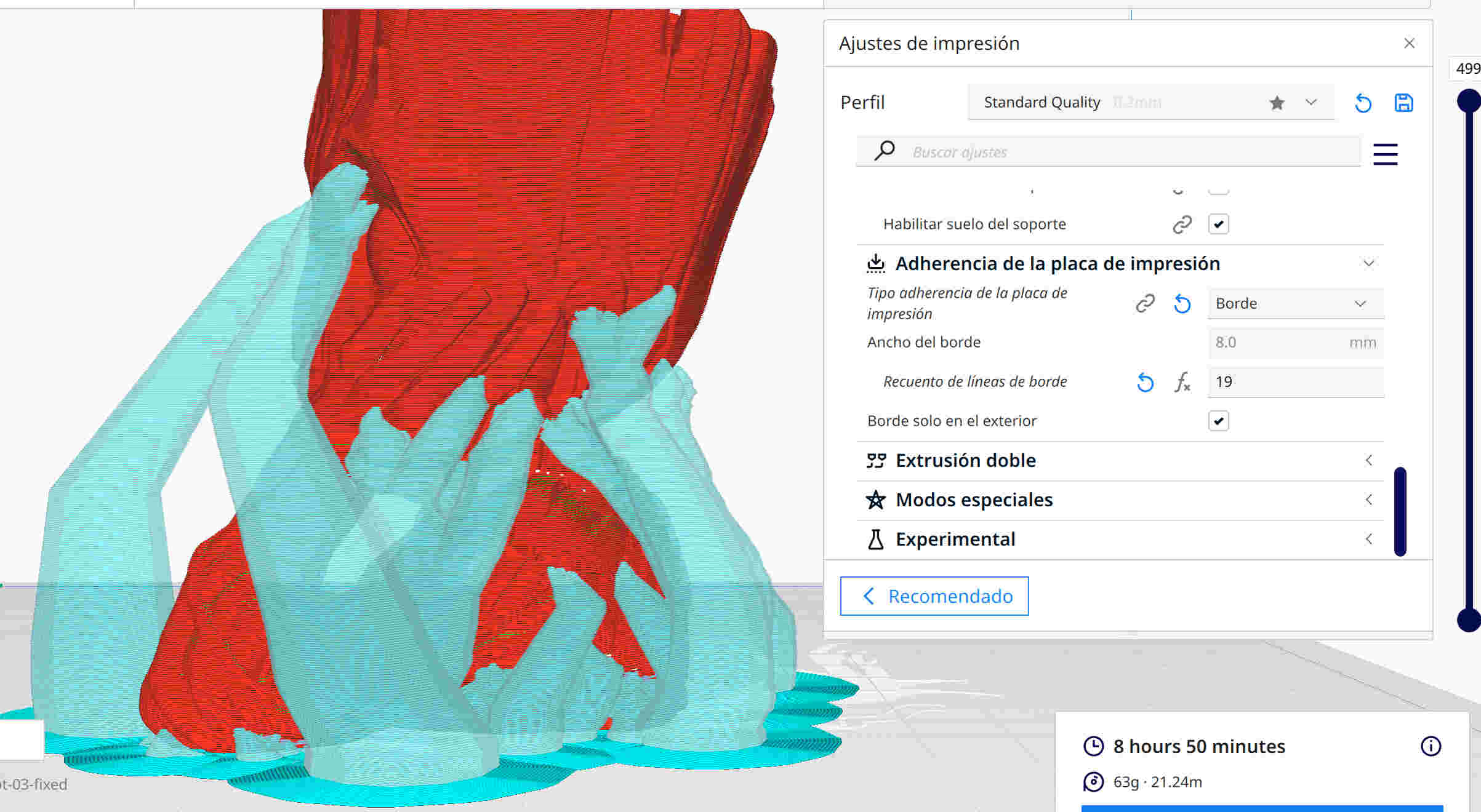
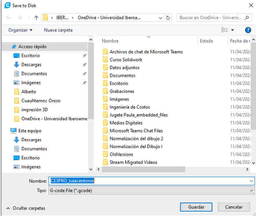
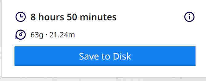
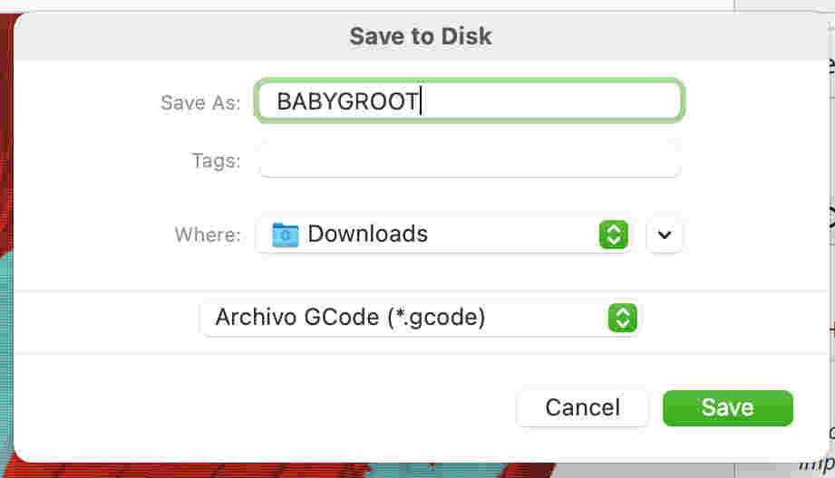
file preparation for the 3D printer
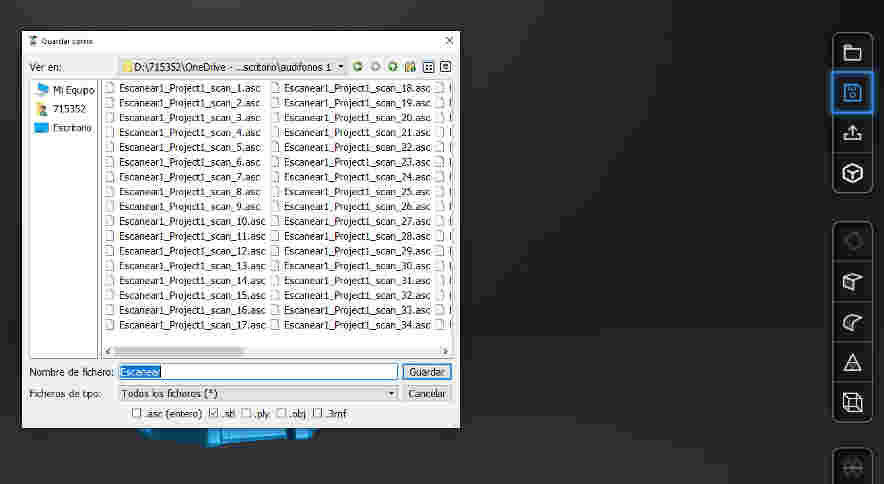
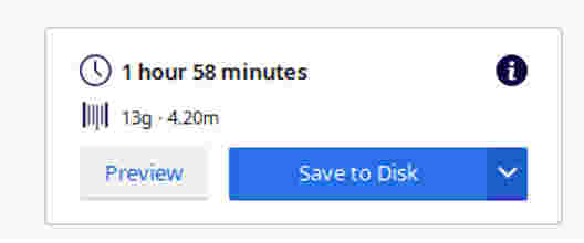
At the bottom right, I find a window with a button that allows me to save and export the file, generating the "G code". These will be the parameter and coordinate instructions that my machine will read to create the physical model. I must save this code in the Micro SD of my machine, since I do not have a USB opening.
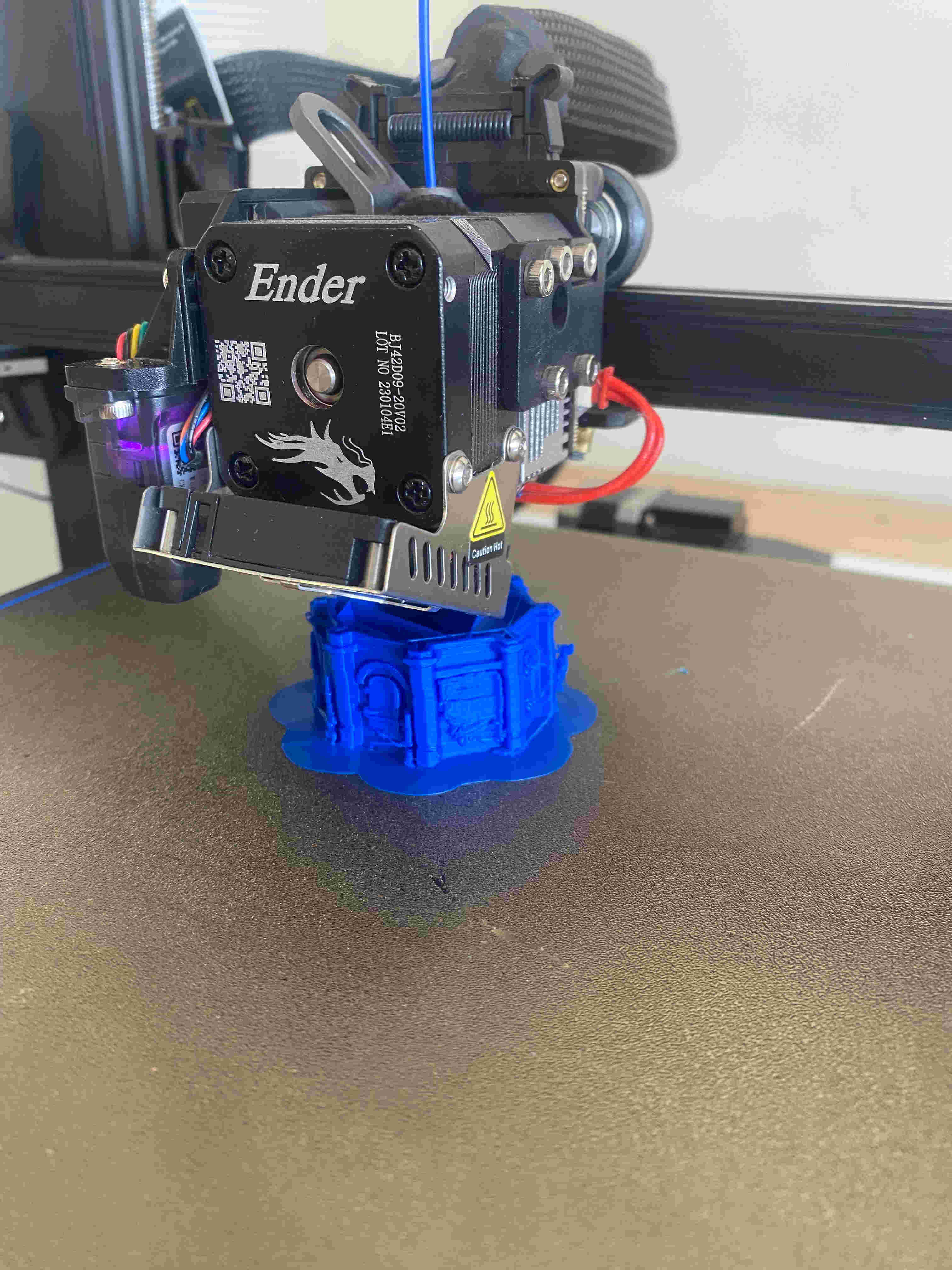
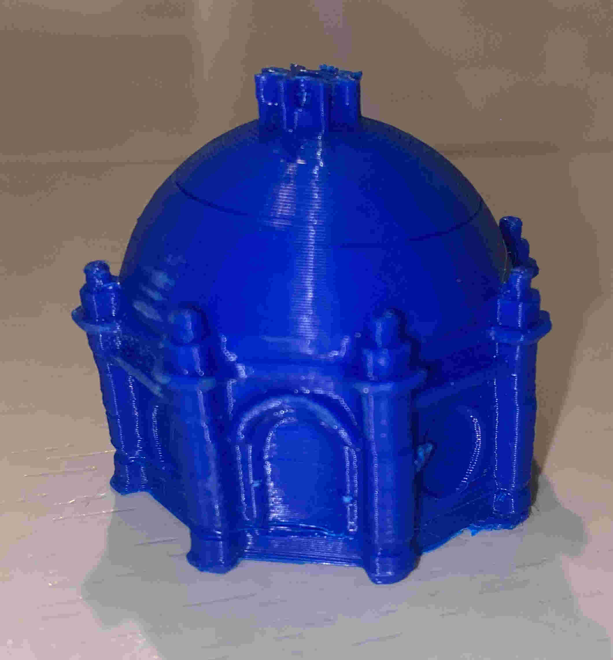
results
The printing results came out very well and I decided to do other tests to see how it would come out with different filaments.
 Download my Babygroot
After knowing how the 3D printer and its software work, I will design my own 3D model
My model and 3D printing
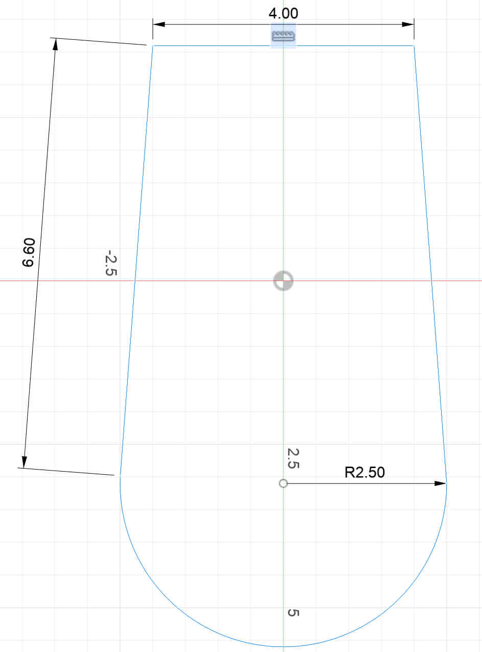
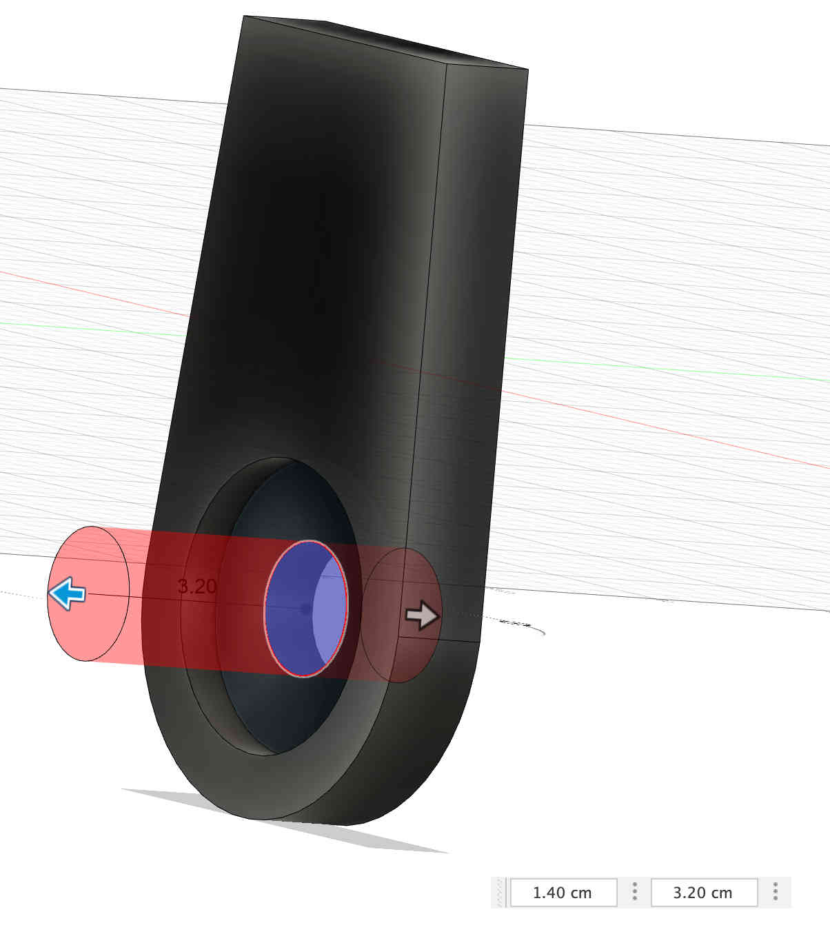
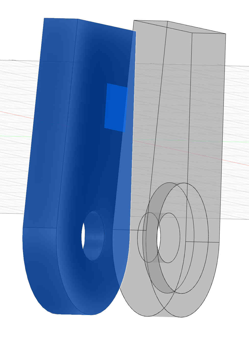
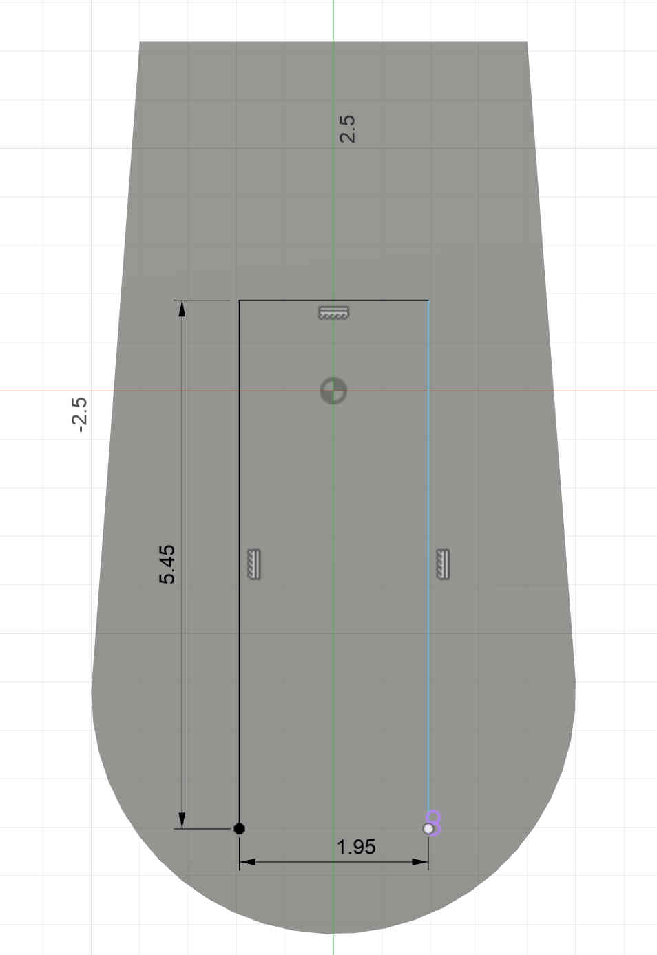
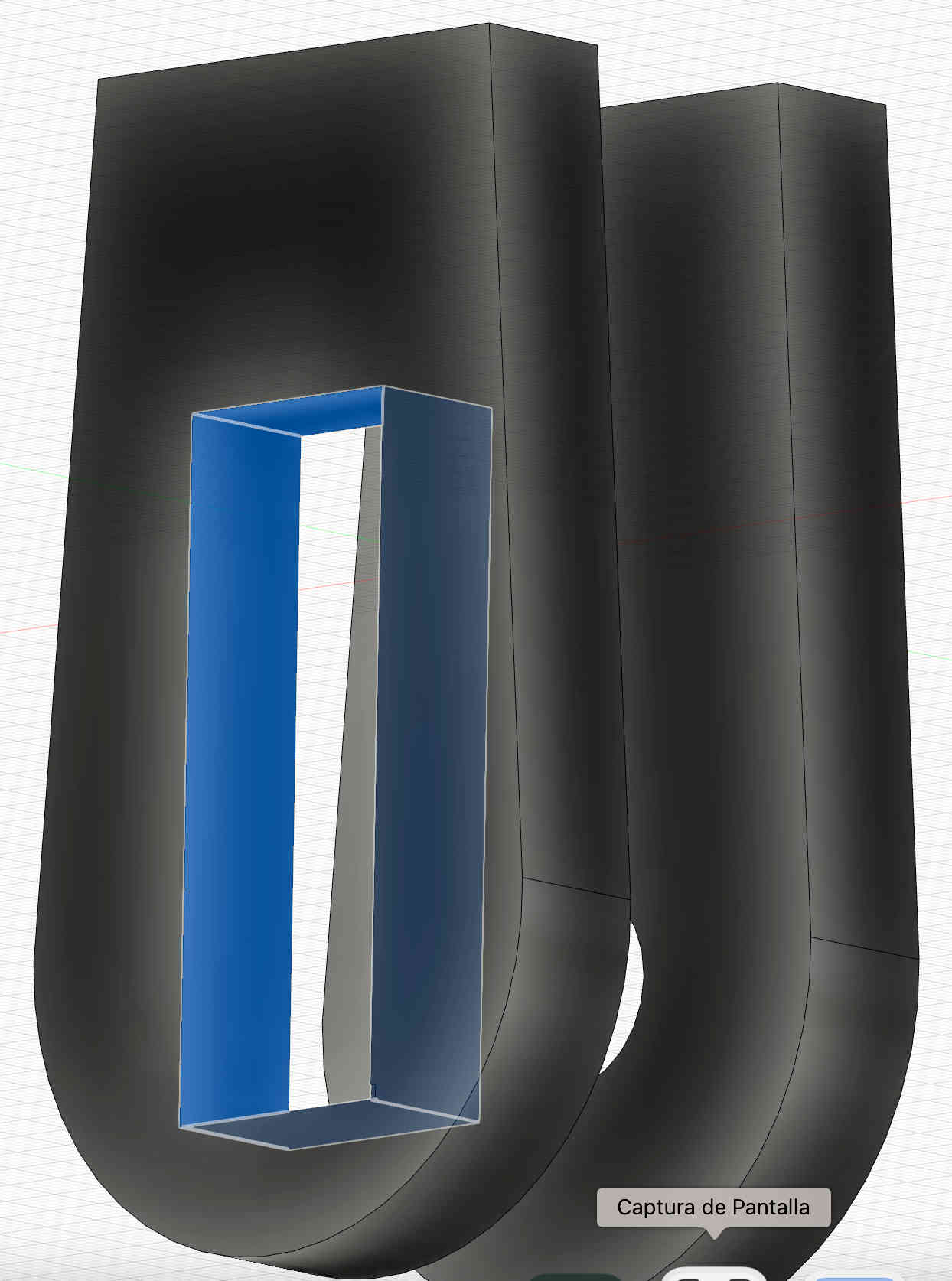
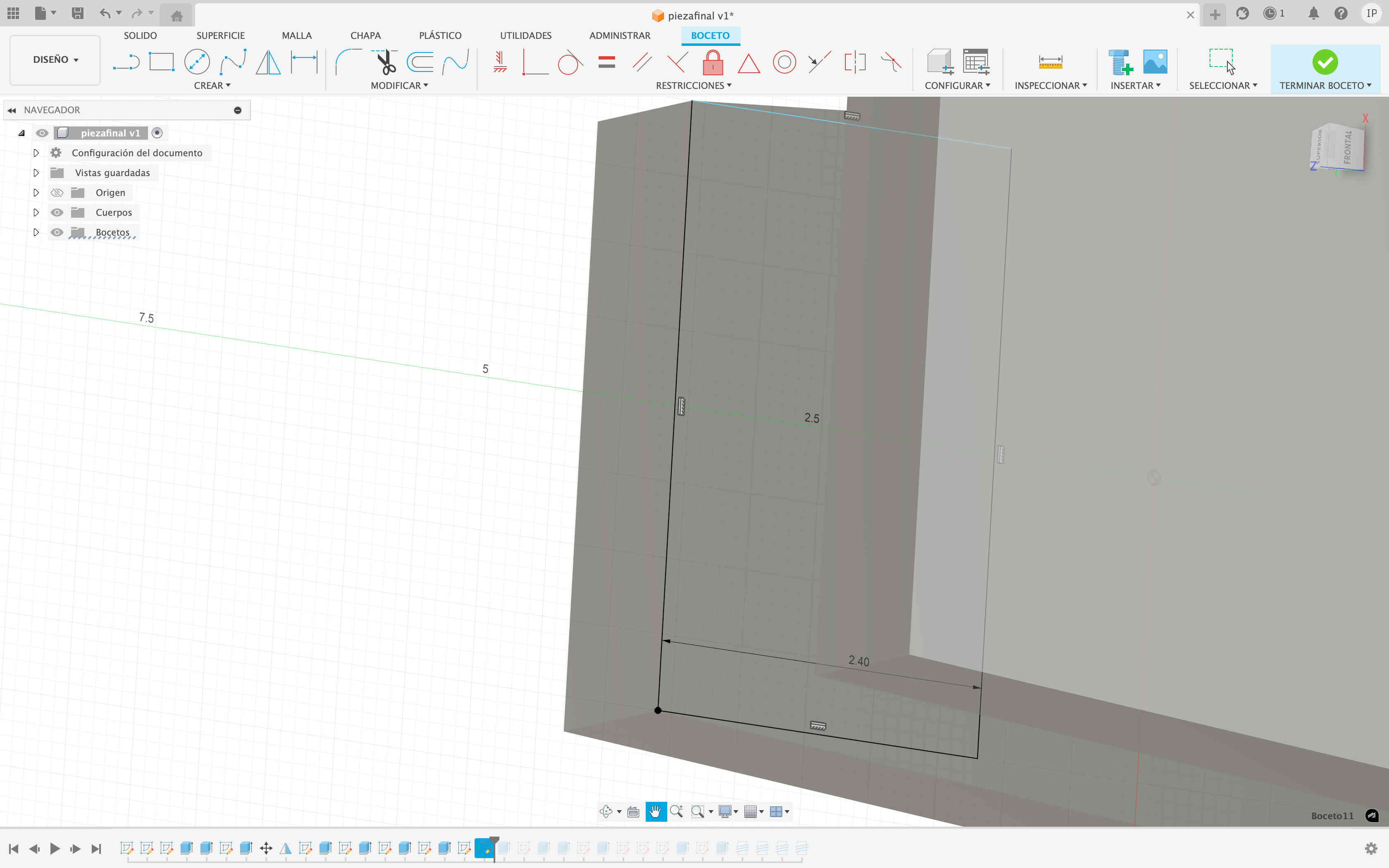
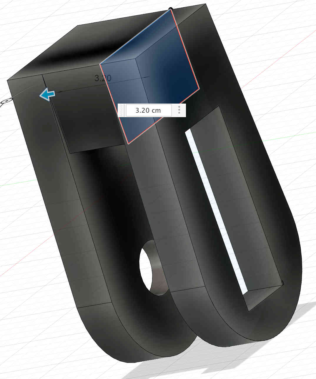
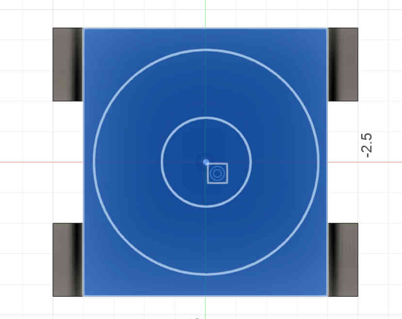
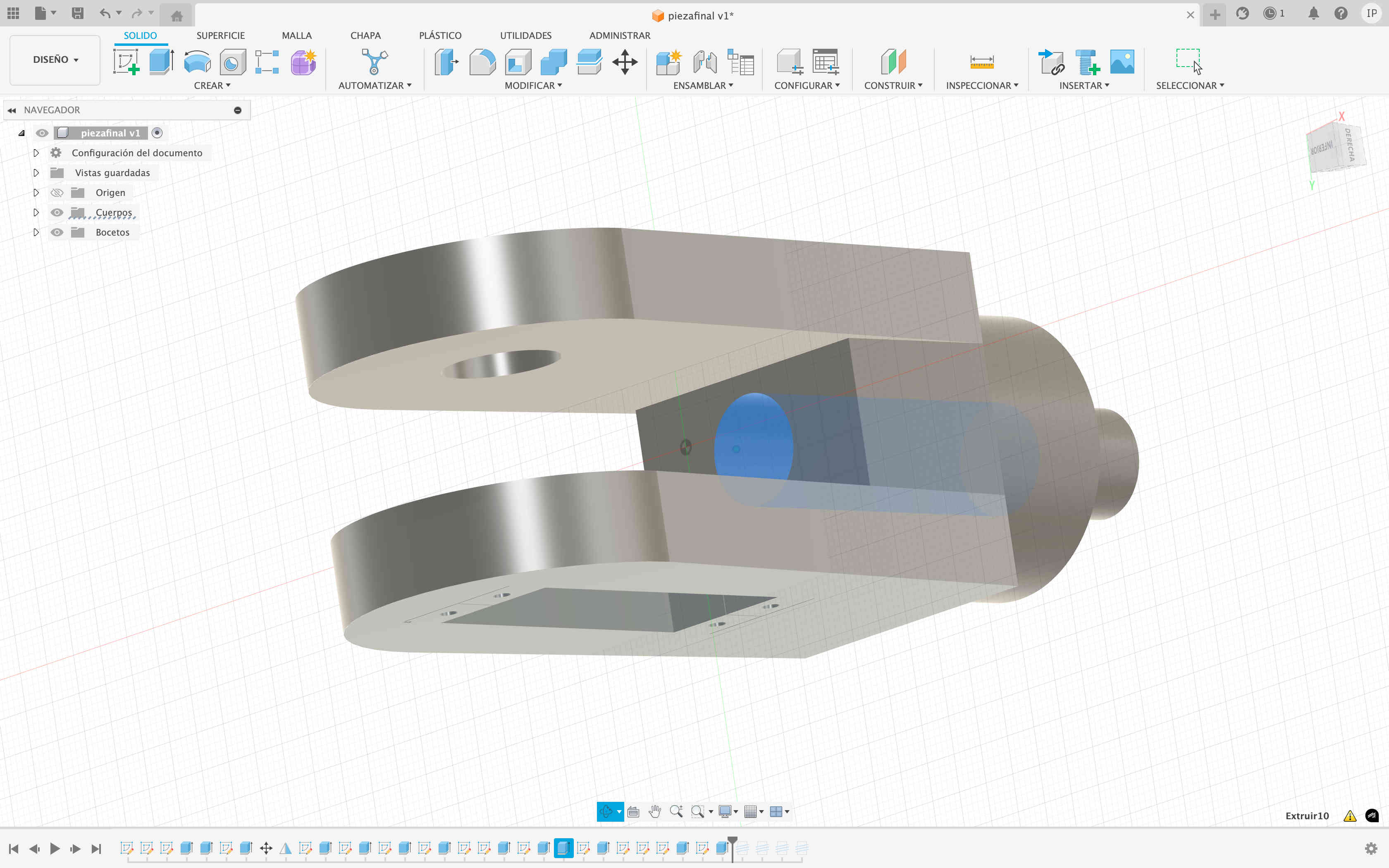
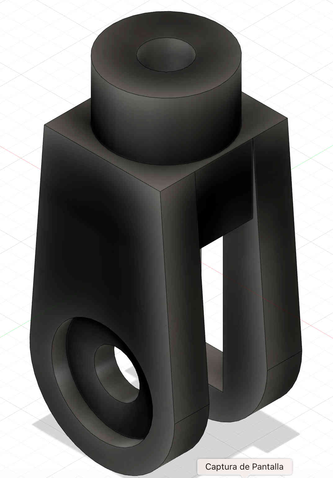
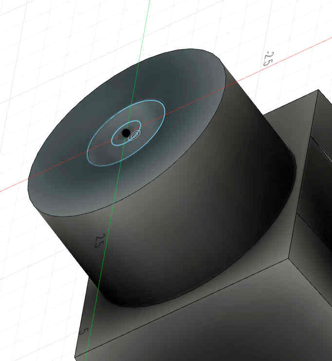
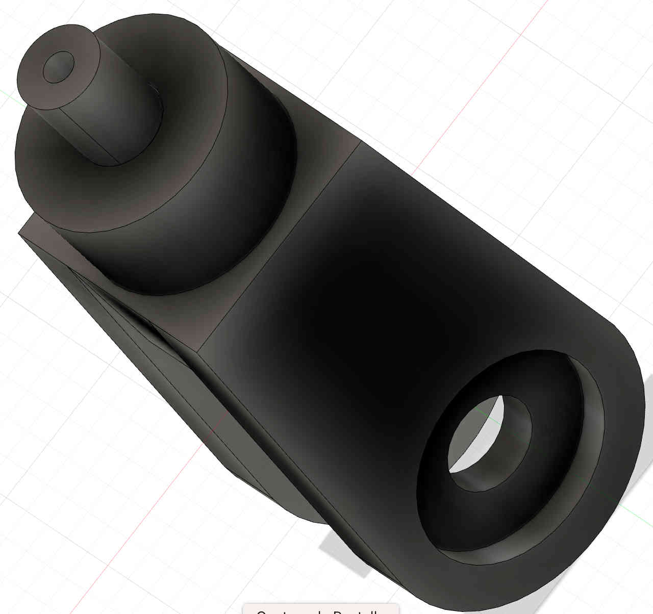
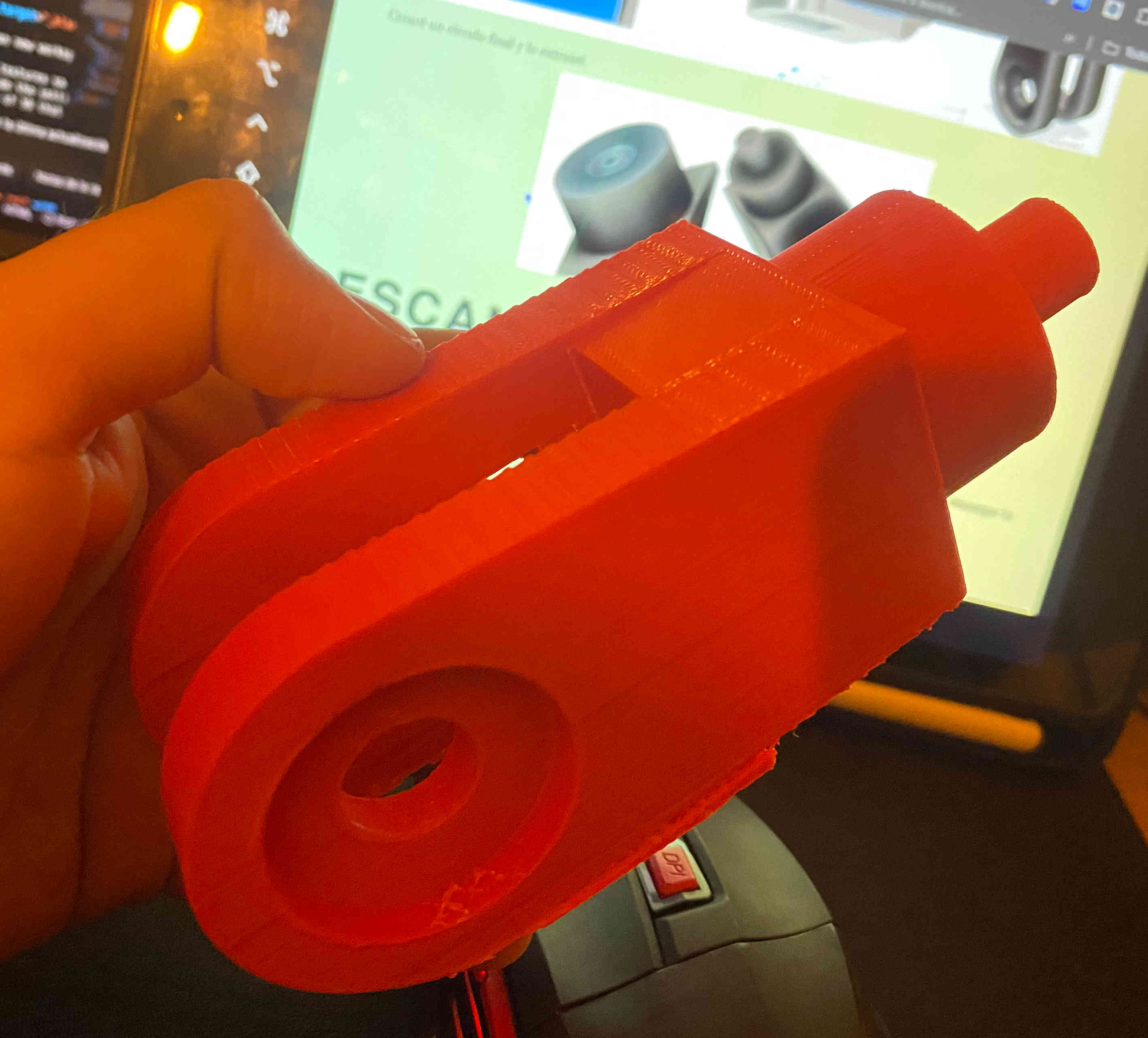
Assembly part for some type of robotic arm
This piece will tool to my robotic arm...when i will have a robotic arm. To start designing it, I used the line tool to draw parallel lines, then closed the shape with the arc function and extruded it. After that, I designed a circle on the bottom side of the piece to cut it, allowing the piece to be held from there.
I need to export my design to STL and put my file in the interface to Ultimatekura and give value to the parameters for my printer Creality Ender-3 S1 Pro v3 PRO.
I'm satisfied with the outcome of my 3D design and printing. It met my expectations.
3D scanning
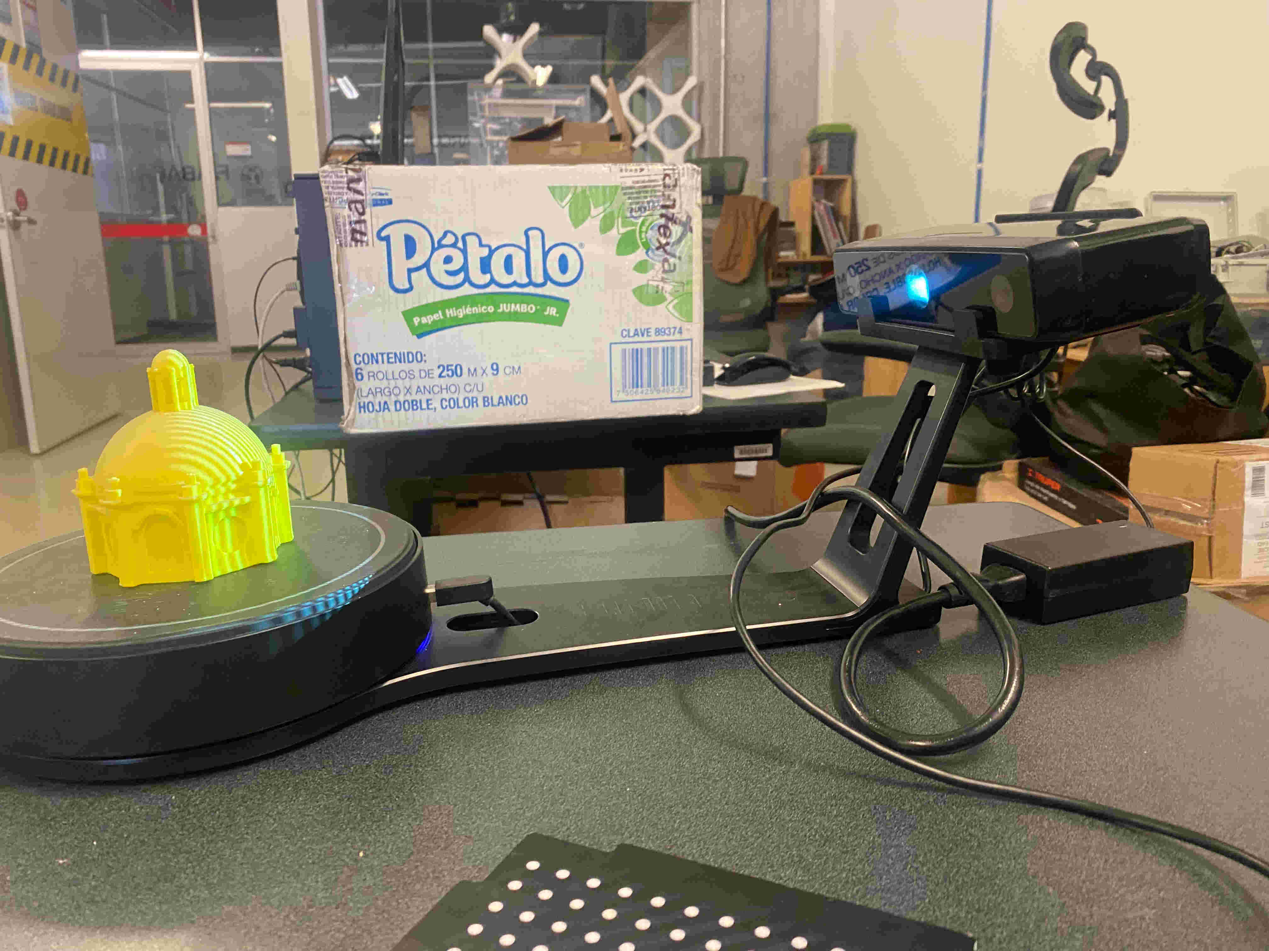
The tool I will use to scan the figure will be an EinScan-SE , i n order to use the scanner I need to download the EXscan application
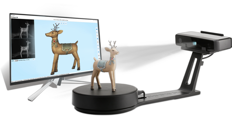
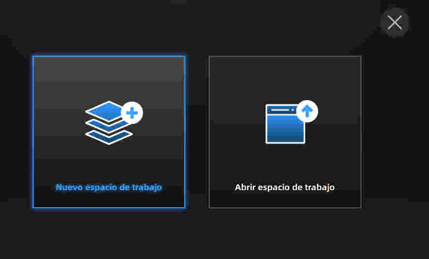
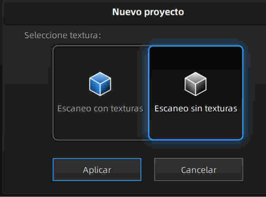
A new options were shown which are used to decide if the scanner will add the textures of the figure. I marked without textures so that the file is not so heavy and click to finish
A window opened for us which will be the one we will work with to be able to scan the desired figure and on the left side the settings that we want to give to the scan will be shown.
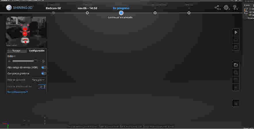
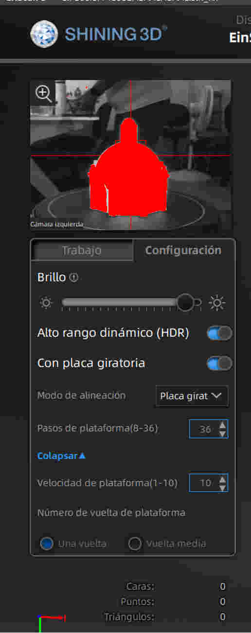
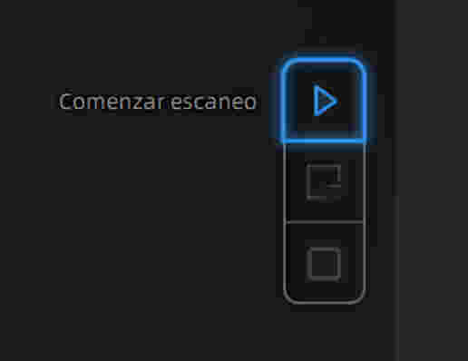
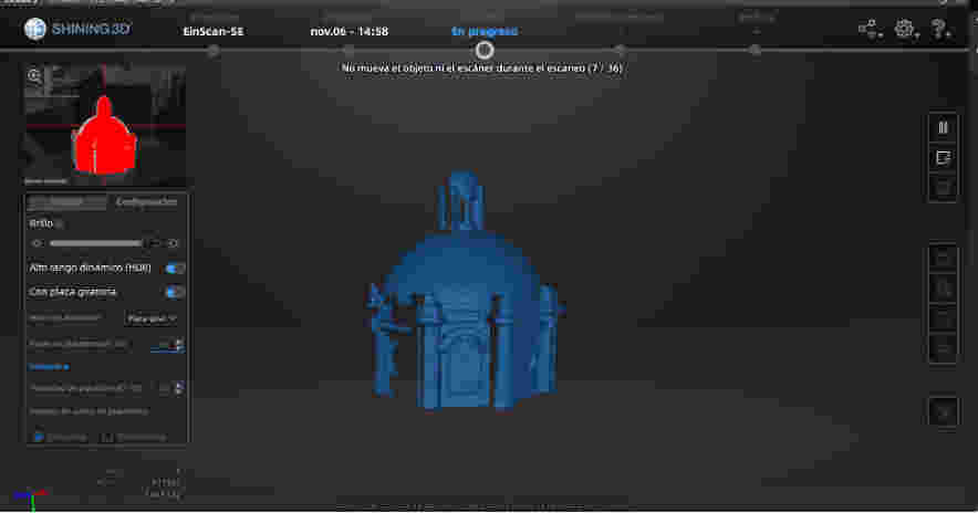
Click on the right button that says start scanning and when you click it will mark at the top how many scans it has out of 36 that it will do to the figure.
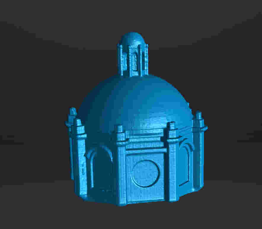
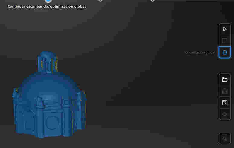
After you have done the 36 scans, click on the right side where it says start editing and an option will appear on the right side where it says global optimization and when you click it will confirm that we will optimize the figure
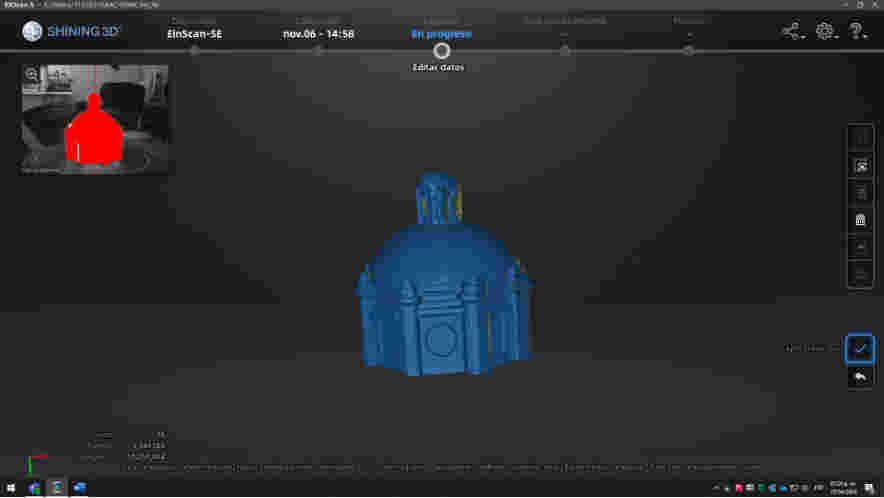
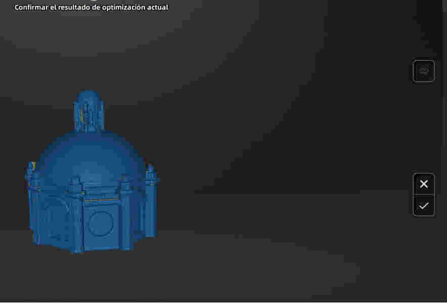
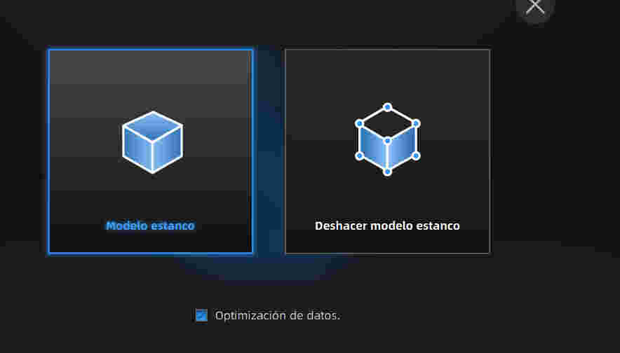
A new option appears called mesh model and when I click it it will open a tab with two options and I will click on the watertight model option and it will show us the more detailed model