Electronics production

weekly assignments

This week was about electronic production; For the assignments we have been asked to create a PCB with soldered components. Our advisors already provided us with the that will be used to manufacture our PCB from which we will have expected learnings which are; learn to build PCBs, learn to solder the components of a PCB and do functional tests of this PCB.

FIRST AND FOREMOST, I SET A SOUNDTRACK TO ACCOMPANY MY WORK THROUGHOUT THE PROCESS(46.-"Iniciales AL(Porte fino)" by Natanael Cano IS MY FAVORITE SONG ON THE SOUNDTRACK).

What is a PCB board?

A PCB board, or printed circuit board, is a structure that contains a complete electronic circuit. Made of conductive material, such as copper, and that form the traces, terminals and other connections of the circuit. Made with insulating material, such as fiberglass, and which provides support to the board and electronic components. The electronic components are assembled on the PCB board and perform the functions of the circuit. In short, a PCB board is like a canvas where an electronic circuit is "painted" using components and connections. PCB boards are used in a wide variety of electronic devices, from mobile phones to computers and industrial equipment.

Router CNC

For the practice of week 4 (Production of electronic products) use a Rolans SMR-20 router.
The characteristics of this machine were presented to us in the Fab Academy Puebla Week 4 group.
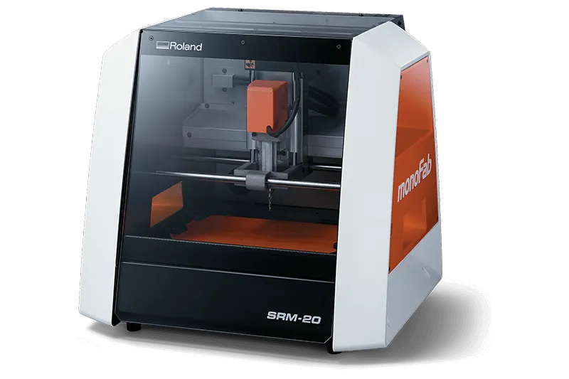
Roland SMR-20

Manufacturer: Roland
Model: SRM-20
Specifications: 203x152x60mm, 1800mm/min, 0.001mm/step, 7000RPM
Applications: Three-axis precision machining, including PCBs with feature size up to 0.25mm and machinable wax for tooling for molding and casting.

My PCB

  1. In order to start the process we need to install theVPanel program to be able to operate the program; already installed, if the machine is not connected to the computer it will not open no matter how hard you try.

  2. ·To make the cut I will need to create a sacrificial bed which will allow me to place the copper plate and there will be no problems with it moving since it will be screwed The sacrificial bed will serve to avoid damaging our aluminum base and to place and remove the piece more easily.·

  3. I will stick the entire surface of the copper plate with double-sided tape and stick it on the sacrificial bed.

  4. Now gluing the copper plate well to the sacrificial bed, the sacrificial bed will be fixed to the machine with the screws that the machine itself has.

  5. With the template provided by our consultants in PNG for the PCB, I will create the program that will be loaded into the CNC router.

  6. On the MODS page, right click to select the program option and search for the machine with which you will work (Roland SMR-20) and finally click on the PCB option.

  7. On the left side of the MOD's window you will find a window which has the option "Select PNG file" and the photo of the PCB vector will be loaded and below that box in the window below you will click on the "button" mill traces(1/64)".

  8. On the right side where the solid line (blue line) there is an off button. It needs to be turned on for the file to download. Likewise, there will be a window where the origin parameters will have to be changed in X, Y & Z, they will be set to 0 as the starting point.

  9. on our cnc router place the V cutting tool with the help of an Allen key.

  10. With VPanel already connected to the computer and it is working, we will use the buttons that are used to move around the machine. We will place our cutter in the coordinates that we feel most comfortable with, in my case in the lower left corner (X,Y) and touching the plate (Z)

  11. With the X/Y and Z buttons (right side) the current coordinates will be saved so that the position is not changed later and the lines are not correct.

  12. By clicking on the cut button, a new tab will open where we will have to click on the "delete all" button to then load our rml file that was automatically generated on the MOD's page and to finish we will click on the button "Output" so that the router starts cutting the traces.

  13. When the router stops cutting the strokes, the cutting tool must be changed to the cutting mill. Only the origin of Z will be changed a little lower. The coordinates of X/Y will not be touched at all.

  14. In MOD's the PNG cut image will be loaded, we will click on the invest button and click on the calculate transparent copper button (1/32). And the file generated automatically by MOD's will be loaded to make the cut with the mill tool.

  15. Finishing cutting the board with the mill tool, the PCB will be detached from the sacrificial bed and it is ready to start soldering the components.


PCB soldering

  1. Sand the PCB so that it has better aesthetics

  2. Our fab academy advisors provided us with a couple of photographs which I used to identify where each component went and in orientation.

  3. Using a 340° soldering iron, place several solder points in place of each component.

  4. To ensure that it stays in its position, place the soldering iron to solder and heat the tin and with small, pointed tweezers place the component on top of the tin.

I'm not the best PCB welder but I managed to finish it with some burns on it.

It works!

Flash Code

In order to test that my board works, my instructors will provide us with a code in Arduino whose function is to turn on an LED when a button is not pressed and two LEDs turn on when it is pressed.

open the arduino software to be able to upload the code to my board.

search for XIAO RP2040 microcontroller from settings, i click on start so that it loads and I can give orders to the XIAO

Some help

Files