Computer-Aided Design📏
weekly assignments💬
This week we were ordered to carry out two tasks which were to make a parametric kit with laser cutting and a design with vinyl cutting.
>FIRST AND FOREMOST, I SET A SOUNDTRACK TO ACCOMPANY MY WORK THROUGHOUT THE PROCESS(7.-"SABOR A Mí" by Eydie Gormé, Los Panchos IS MY FAVORITE SONG ON THE SOUNDTRACK).
Why is essential learn Computer-Aided Design?🤔
Knowing computer-aided design (CAD) provides advantages such as efficient and precise design, easy editing, remote collaboration, convenient digital storage, 3D visualization, simulation and analysis capabilities, error reduction, scalability, innovation, experimentation, and automation
!Click & Move¡
It seems difficult at first to move around the canvas but the truth is that it is not, it is very simple, almost like a game.
| commands that can be used in the interface catia: | Function | |
|---|---|---|
| Pressing scroll | ⏩ | Allows you to rotate the view in a program using the mouse wheel. It is common in 3D design and panoramic image viewing software, making it easy to explore content from different angles." |
| Pressing scroll + holding right click | ⏩ | Allows actions such as scrolling, zooming or panning. |
The Catia interface seemed a little outdated to me but it works very well for designing any model in 3D.
My work
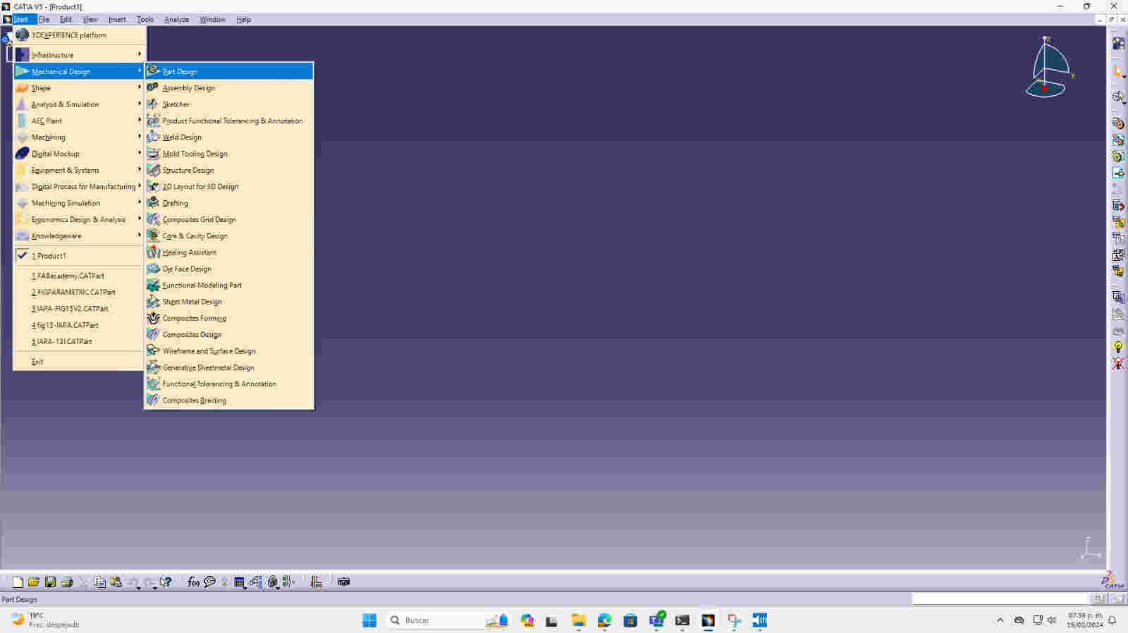
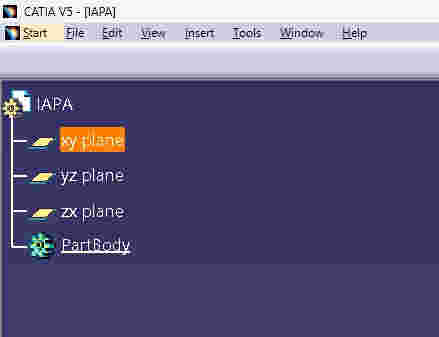
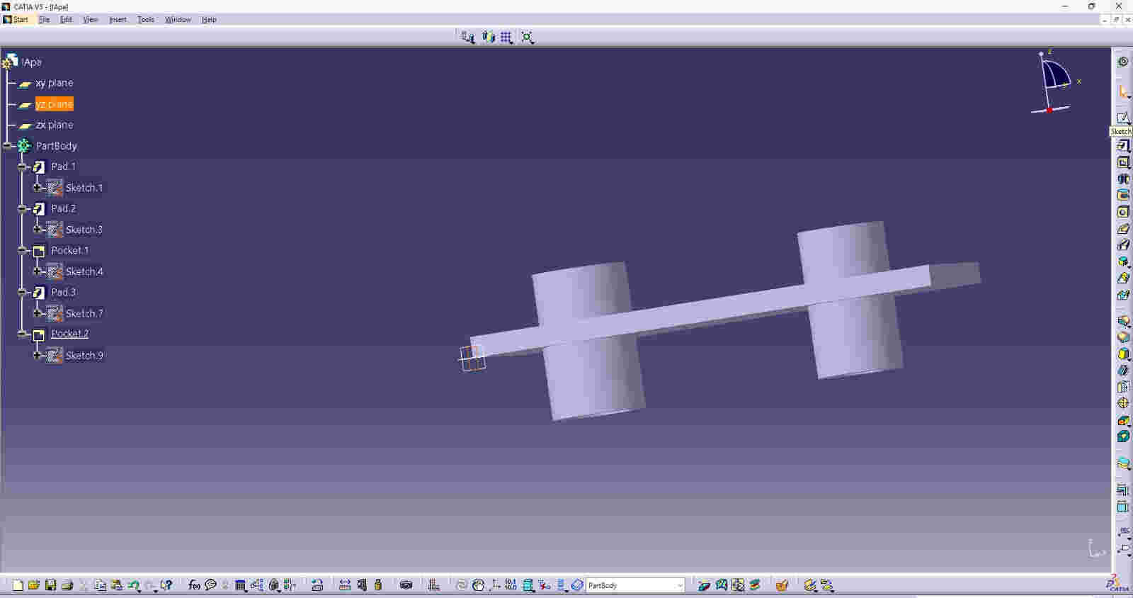
First I clicked on the start button, to create the part I clicked on the mechanical design button and then I selected part design (upper left side).
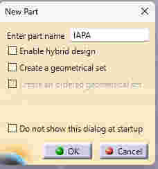
a new tab opens where you can enter the name of the file, so that the instruction tree can be built.
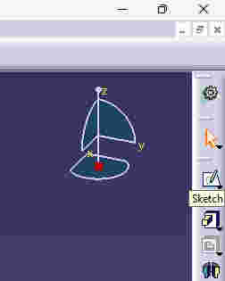
select a plane to start my sketch.(upper left side, buttons XY,YZ,Z)
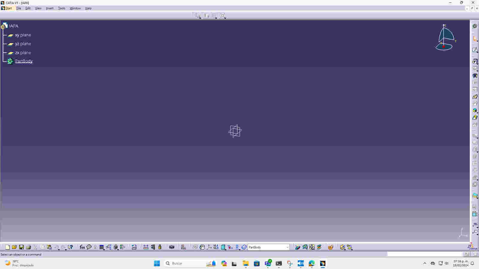
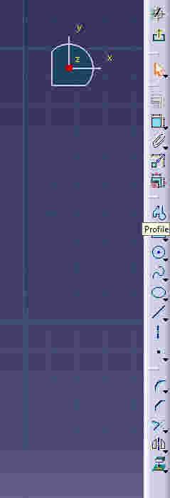
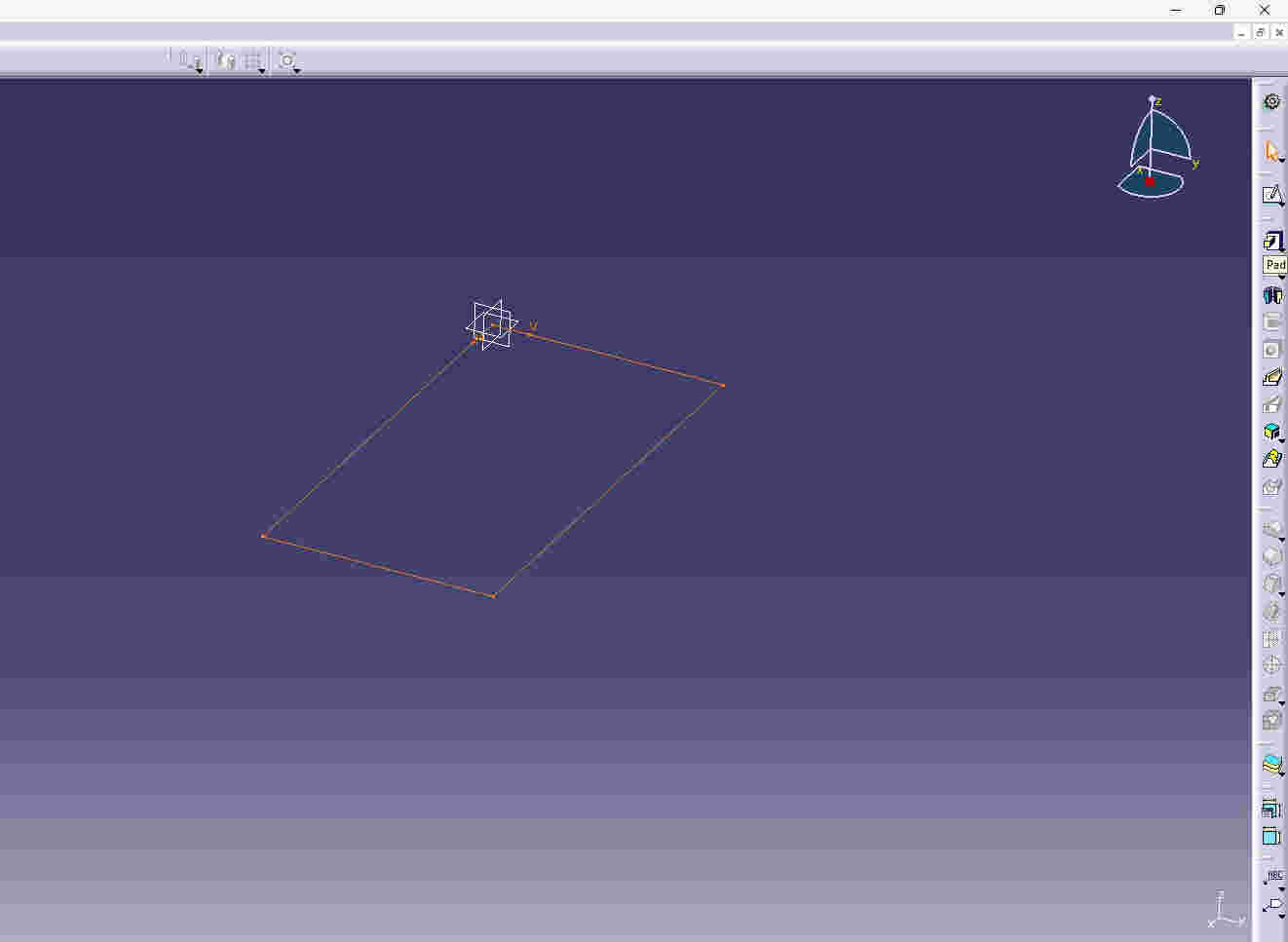
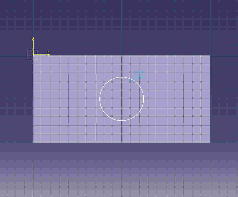
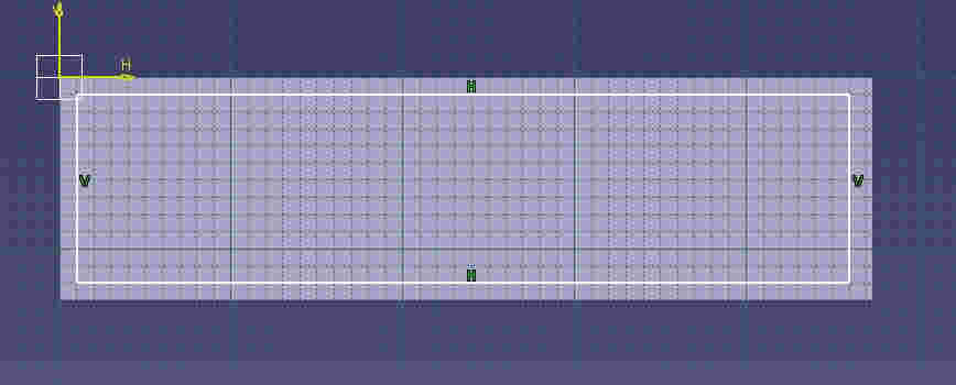
I started my sketch by clicking the sketch button (upper right) and the plane was shown gridded so I could create lines and figures.
Profile button to create curved lines (right side of the window)

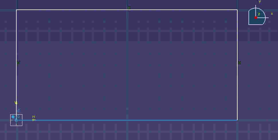
I started drawing lines and giving measurements to be able to create something from the coordinates 0,0,0.
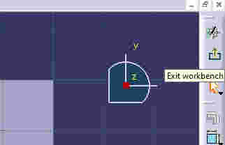
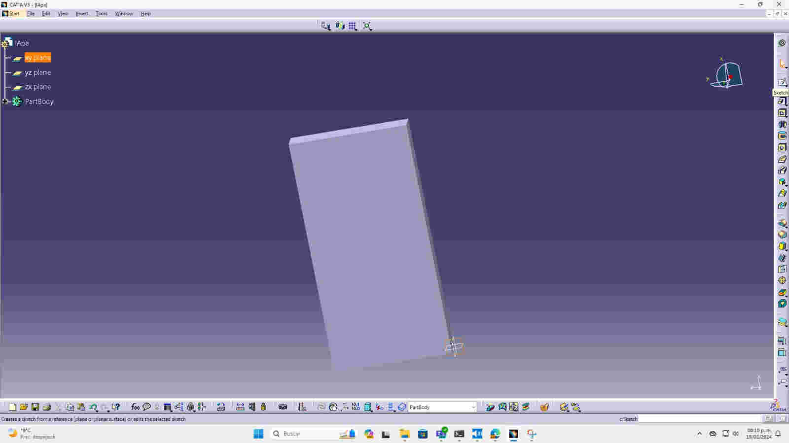
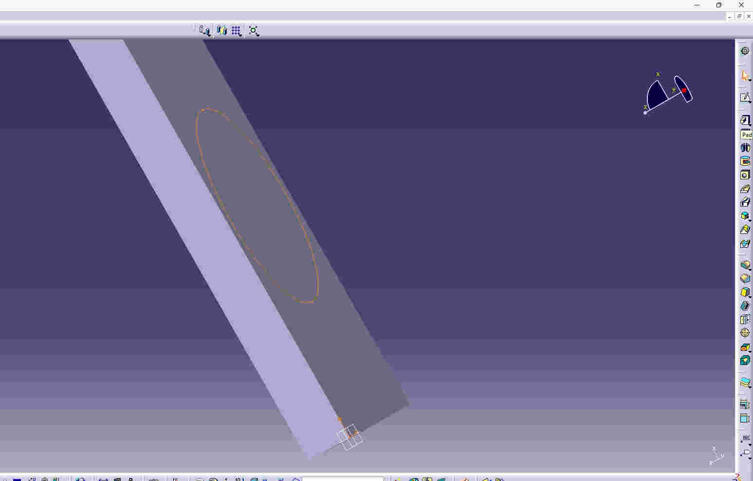
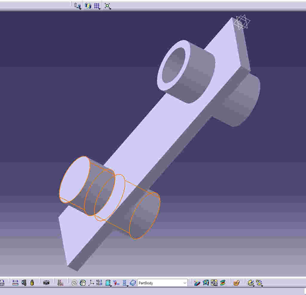
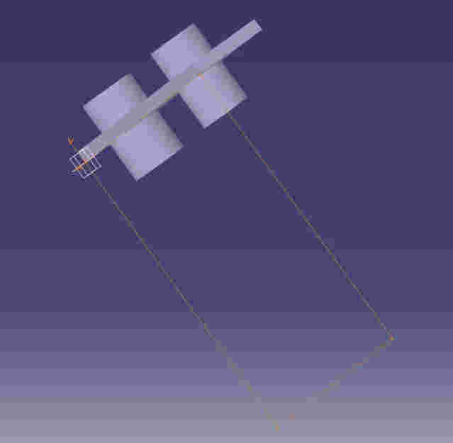
Exit workbench to be able to exit the 2D work area and have a three-dimensional angle.
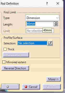
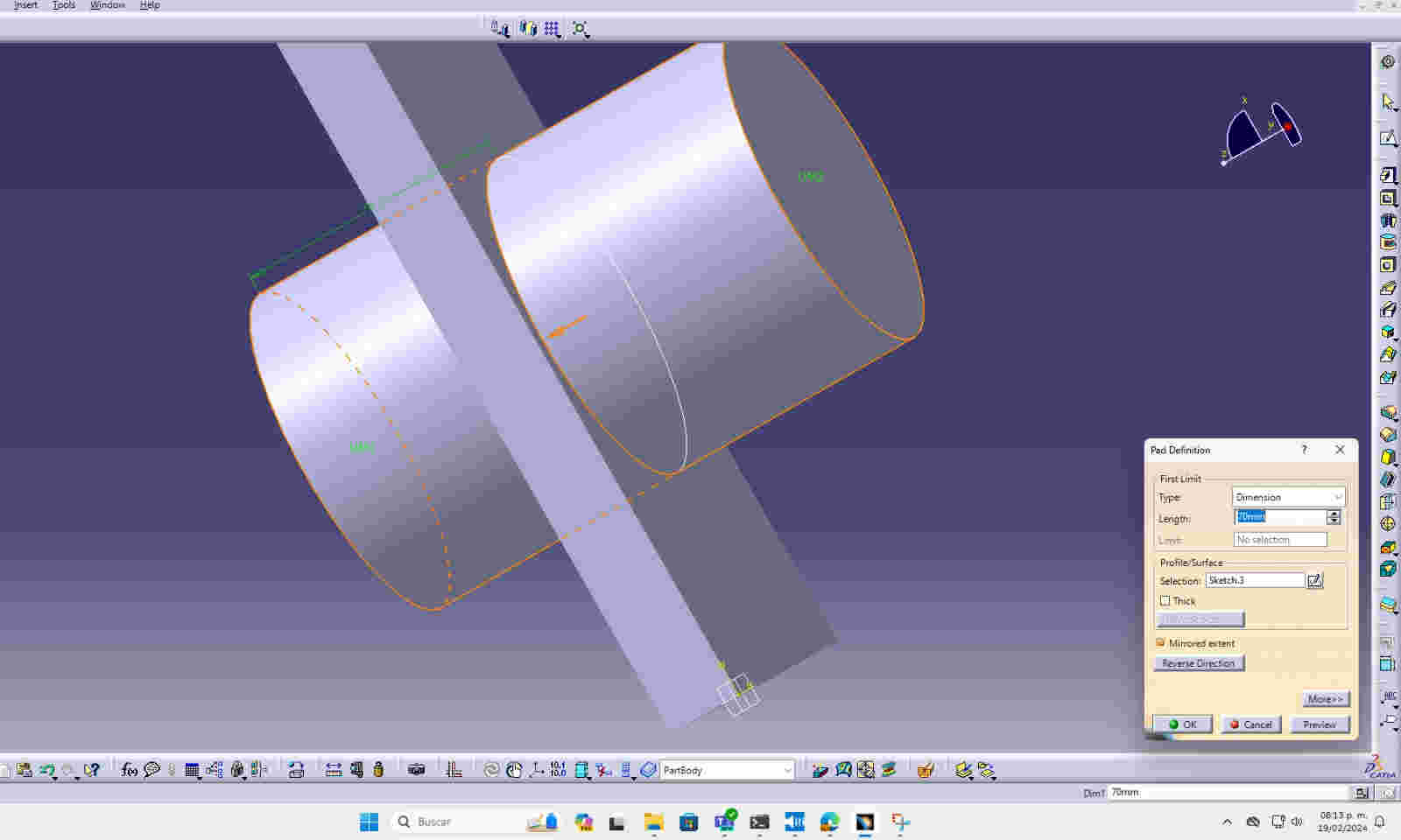
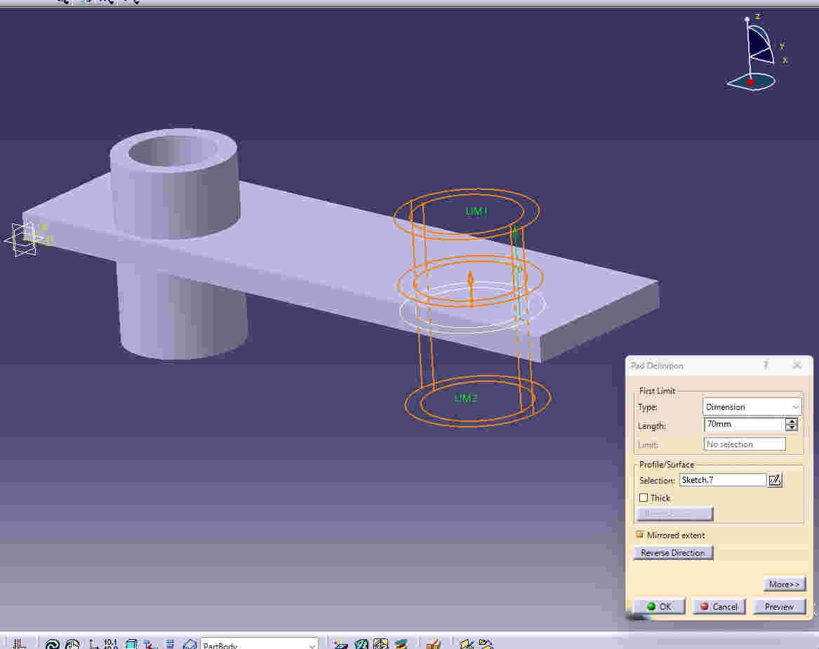
I clicked on the pad panel button so I could create a volume to the shape.
After this put the dimensions of the volume I needed for the piece in the length option and clicked on okay to generate the volume
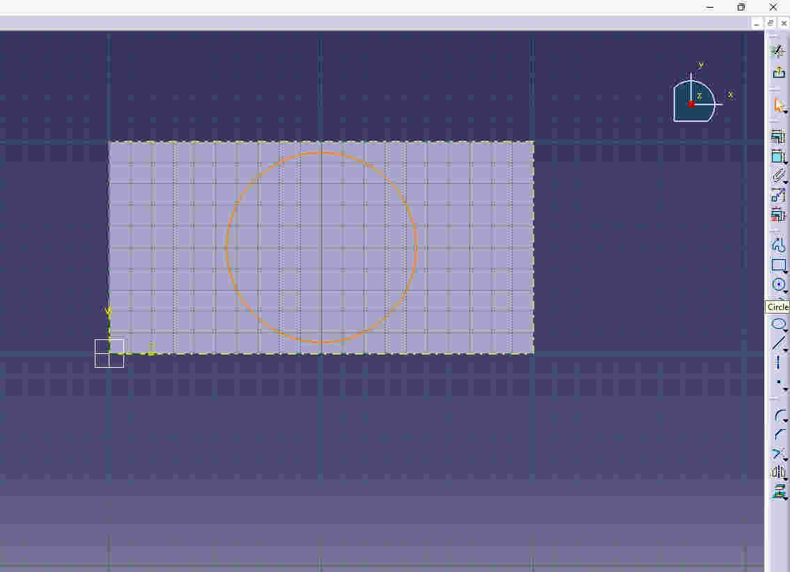
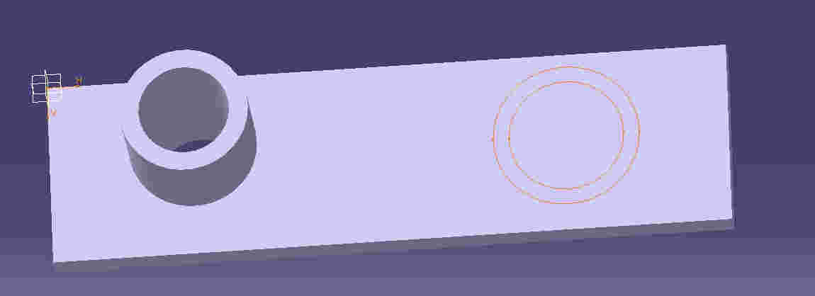
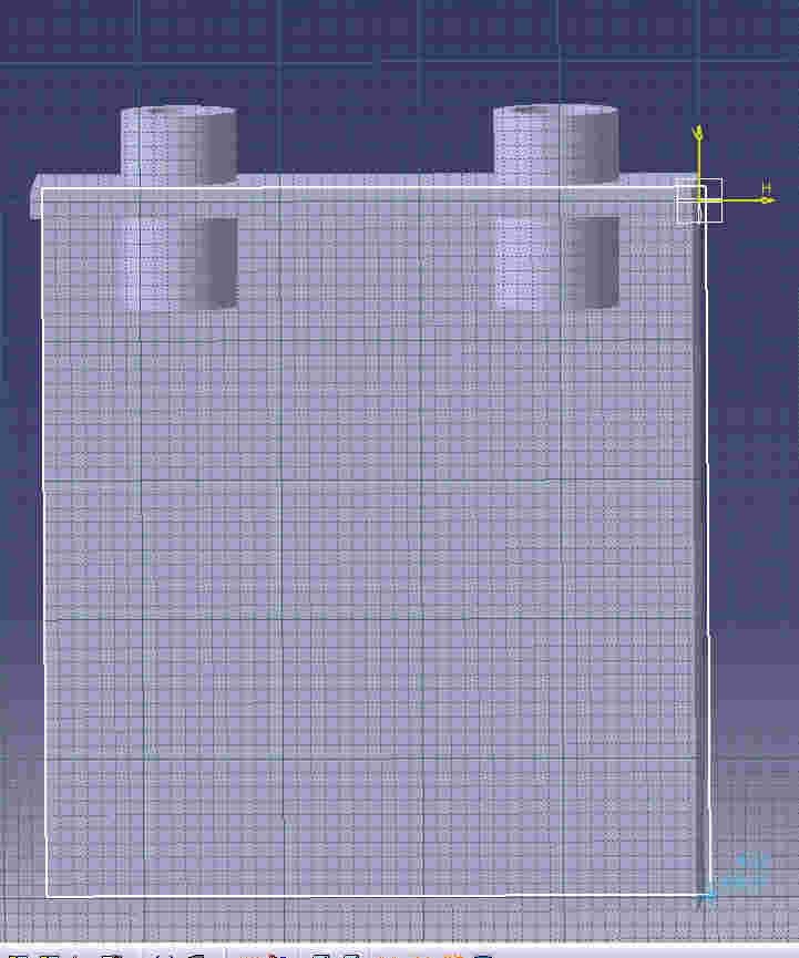
I went to the XY plane and clicked the sketch button to generate a new shape.
I created a circulation so that the gas can escape from one side of the piece. Finishing the 2D sketch, I clicked on the exit workbench button and to have a 3D plan.
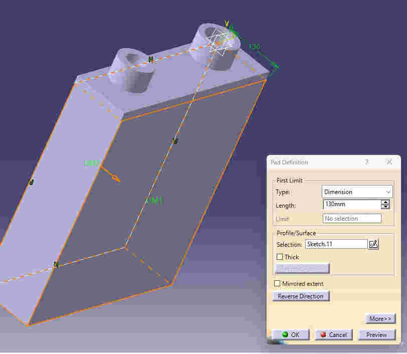
with the pad option create the volume so that the figure, after selecting the pad option I put the dimensions I wanted in the length option.
Finishing the 2D sketch, I clicked on the exit workbench button and to have a 3D plan.
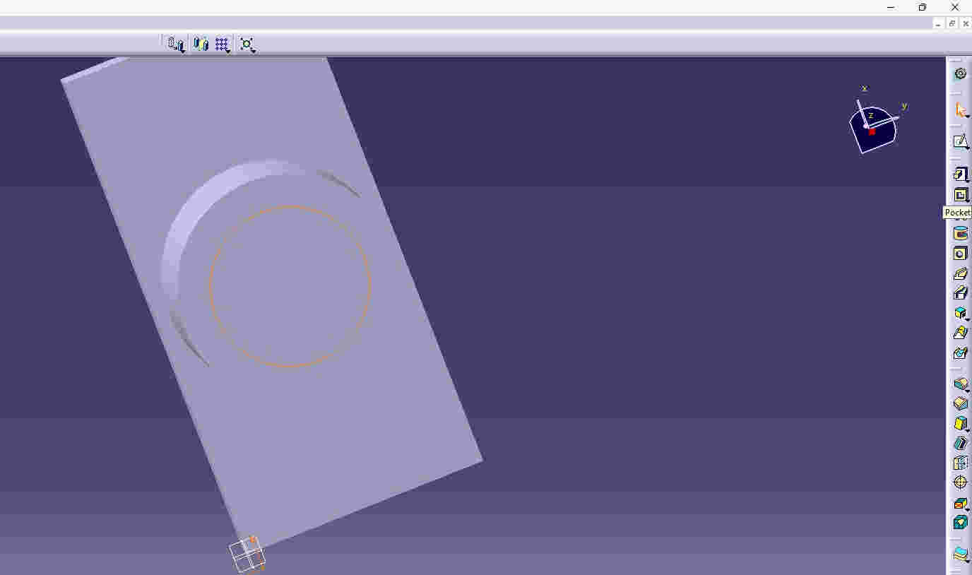
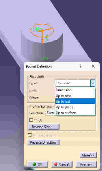
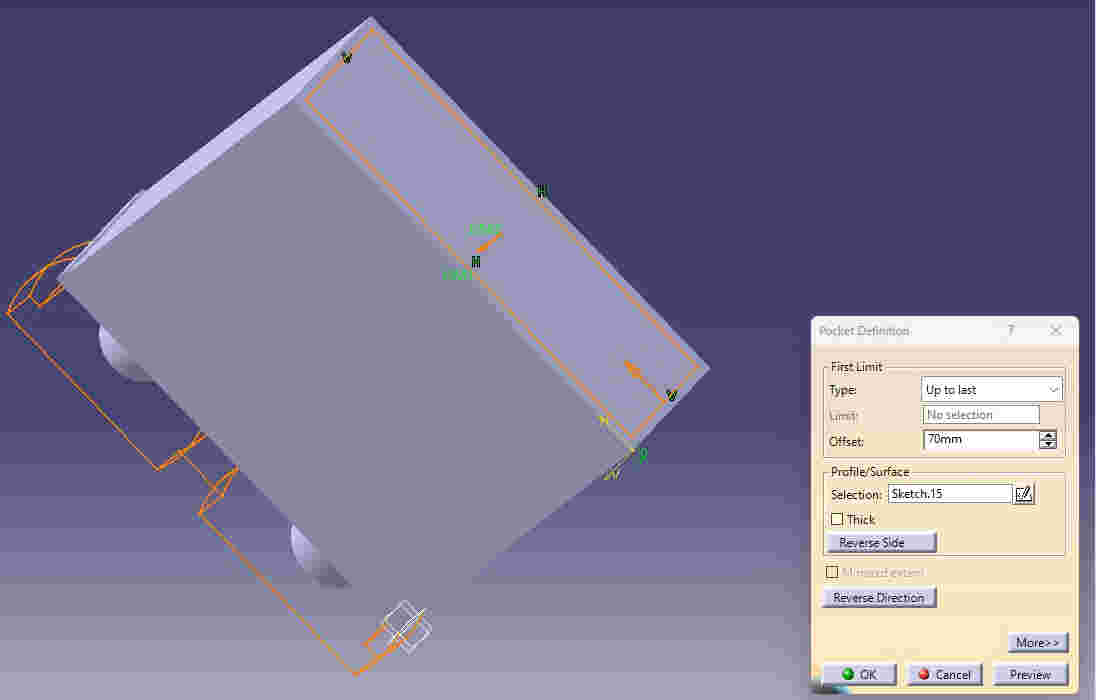
In order to make it have a hole, click on the pocket option on the right side, in the toolbar.
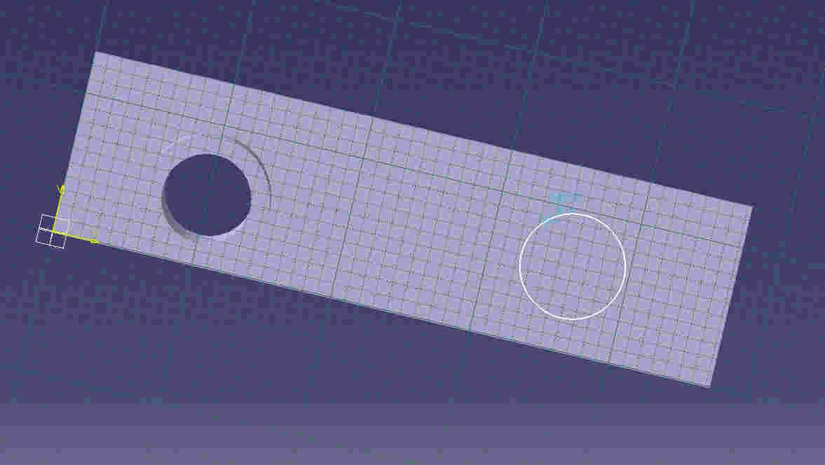
Since there will have to be two identical holes, the same process will have to be done but on one side of the first hole.
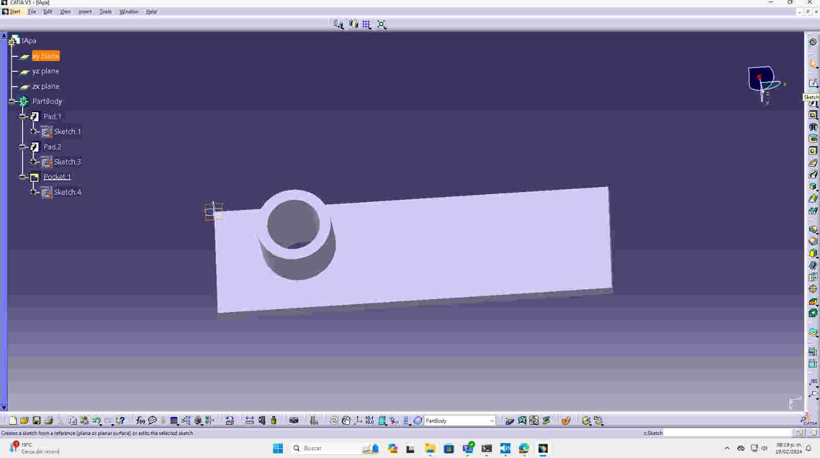
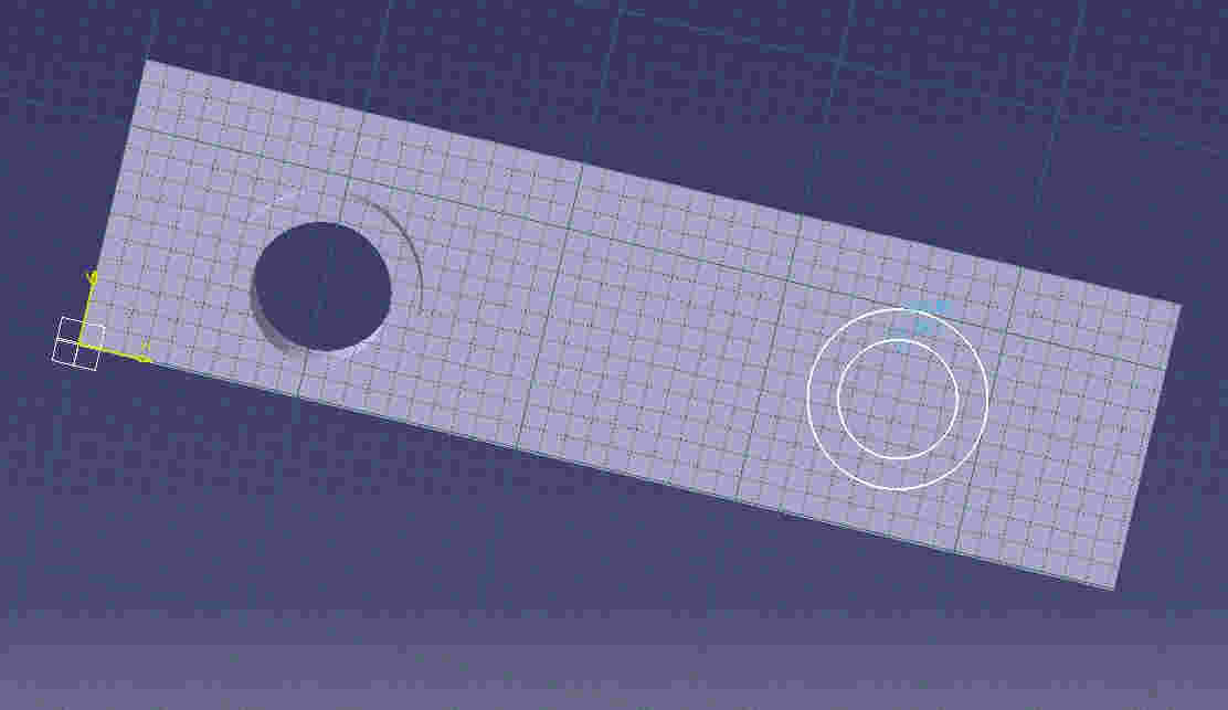
In the part of the toolbar, choose the circle option and then create the volume leaving the 2D plane with the PAD option, then create the volume.
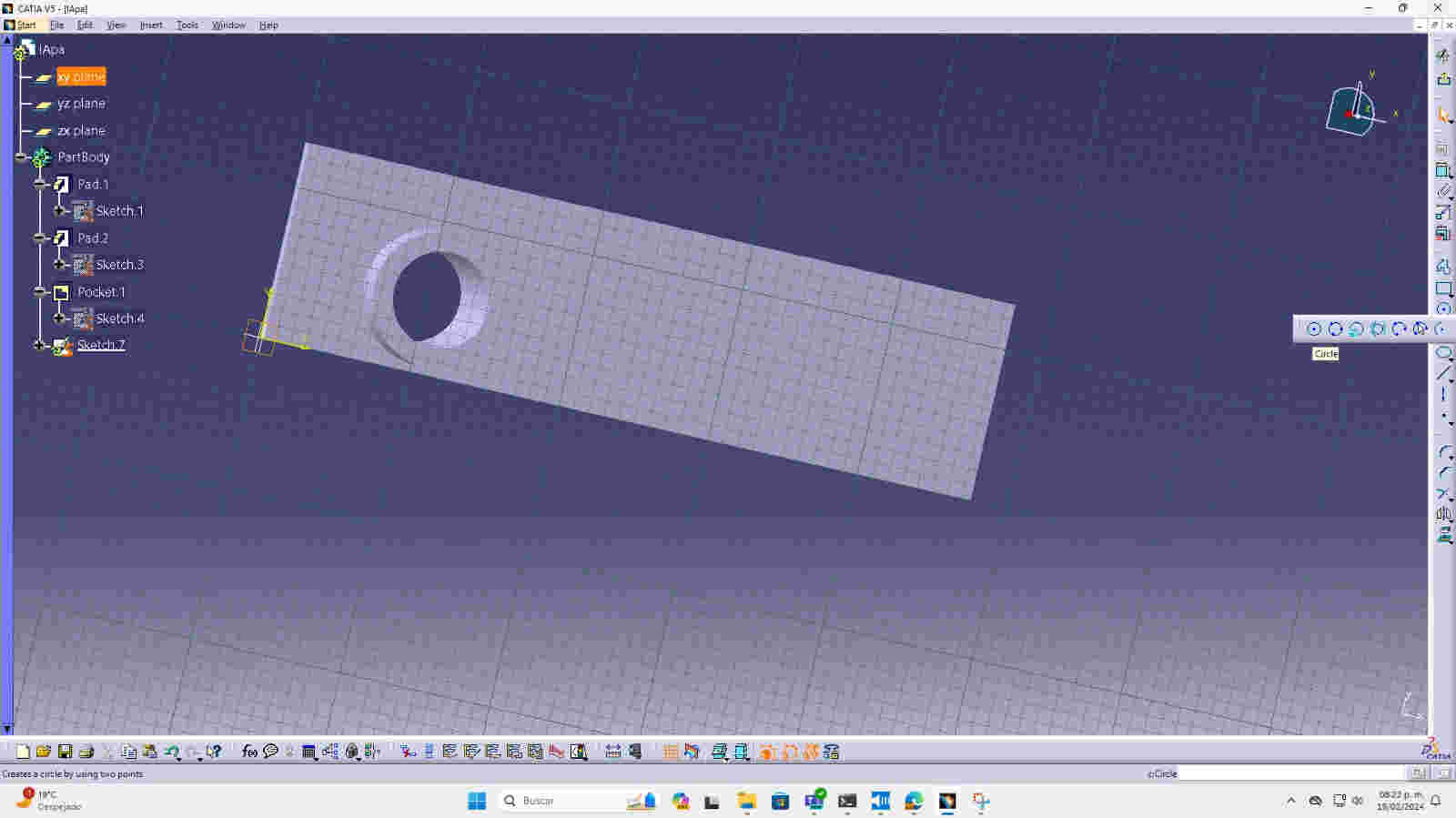


use the pocket option to create the hole and return to the XY plane and click on sketch in order to create the faces of the mold

I will do the same previous step again so that the hydrogen and oxygen can have an air outlet
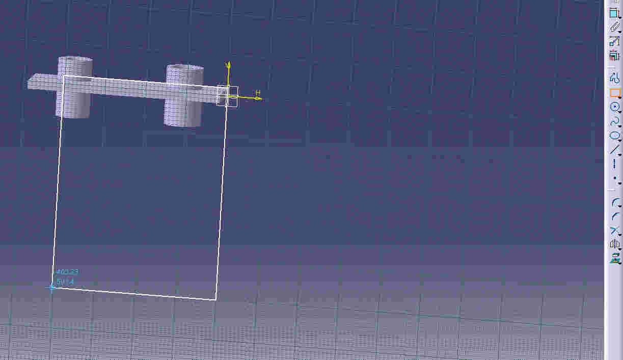

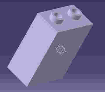
And I repeat the same steps for all sides of the container.

2D Interface:
Corel draw🖌
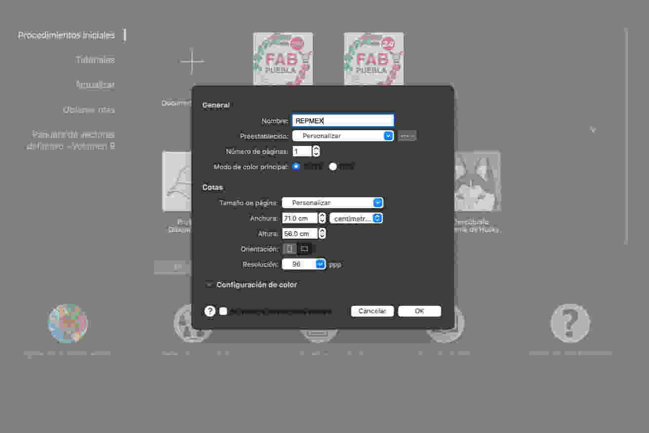
To create a new file, click on new document.
Assign the name of the file in the general>name section and I will also assign the measurements of my file in the dimensions section, in page size click on the customize option and I will be able to assign the values that I want for my drawing in width and height, and Below those options I will still select in which orientation I want it
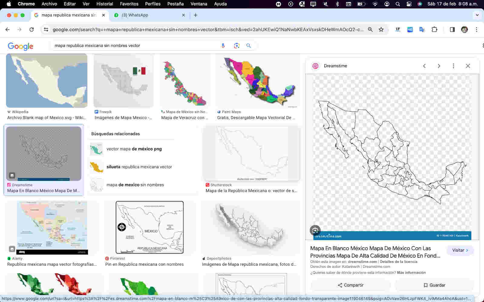
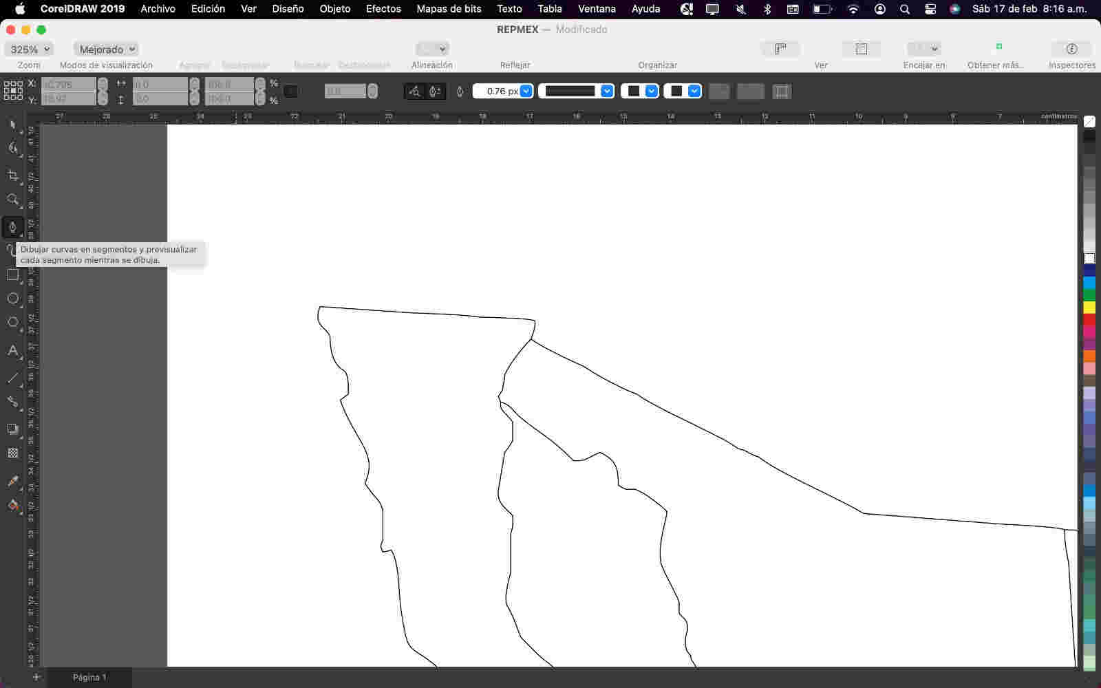
I copied a google chrome image from the "#" site as a reference to guide me in making the vector.
Paste the image on the white canvas to start vectorizing the drawing.
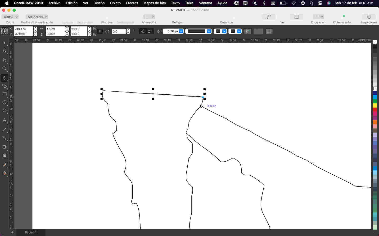
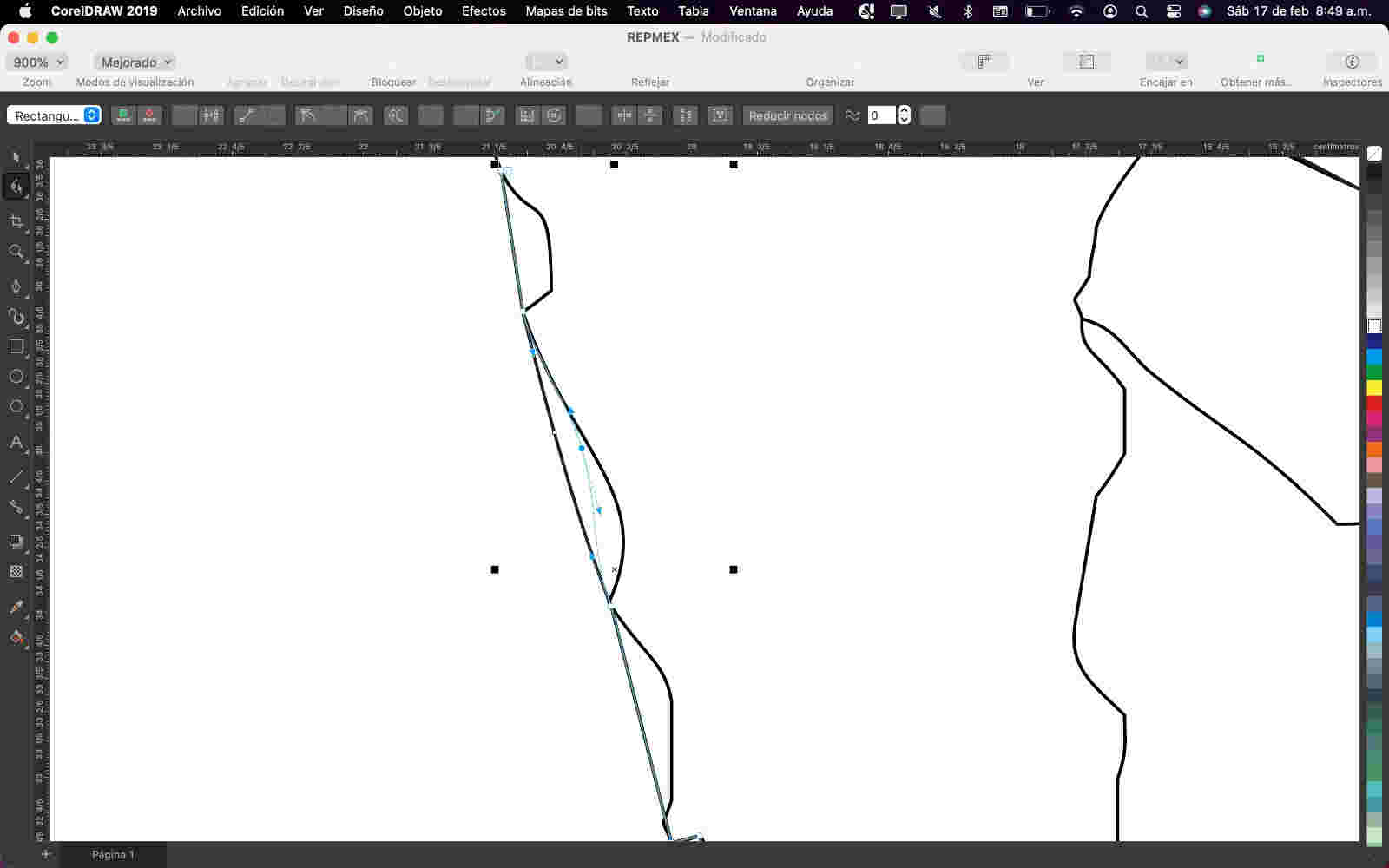
To start drawing the lines use the pen tool (upper right side) so that they can be converted into curves.
I started to draw lines taking as a reference the image I copied from google to get a better drawing.
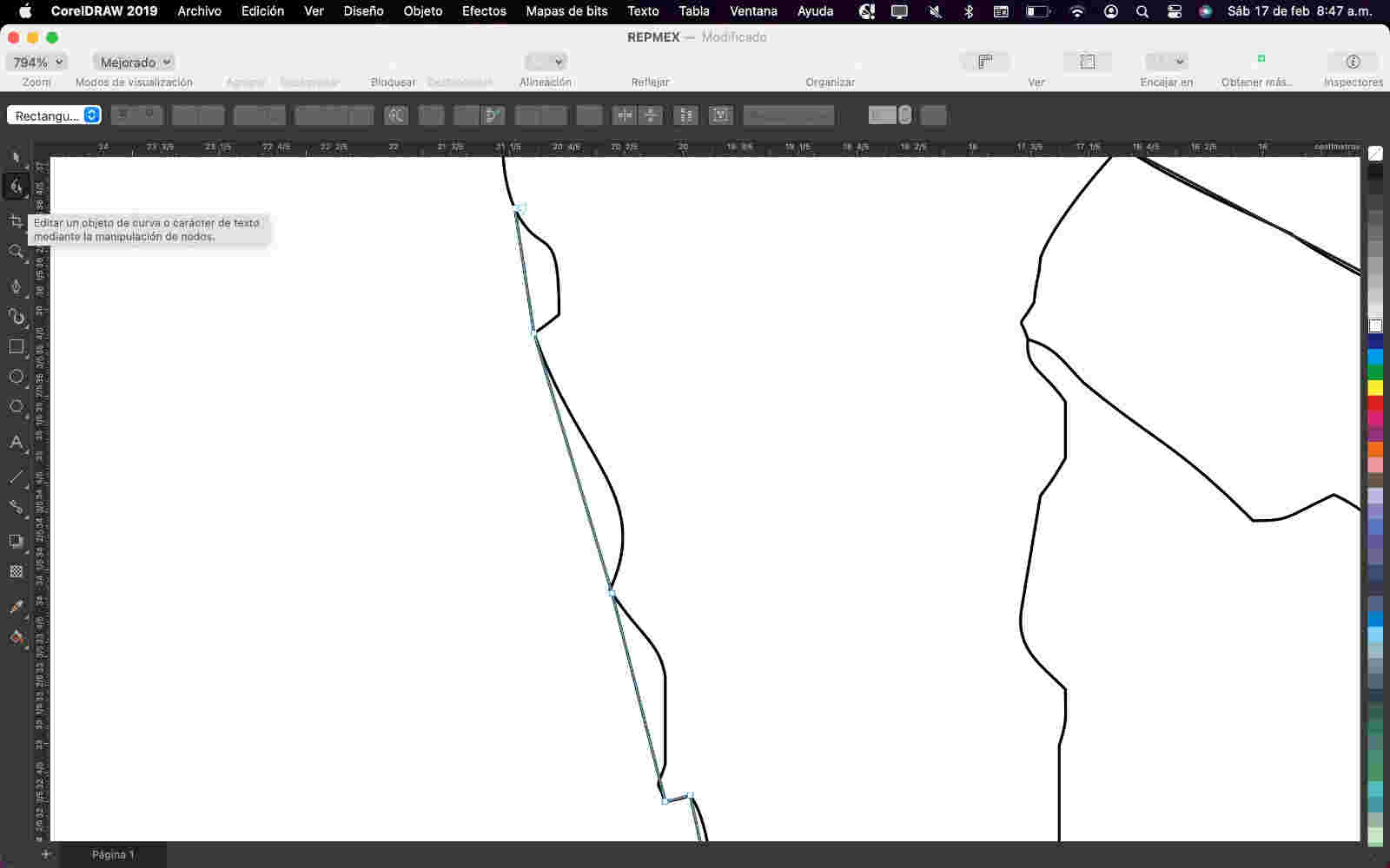
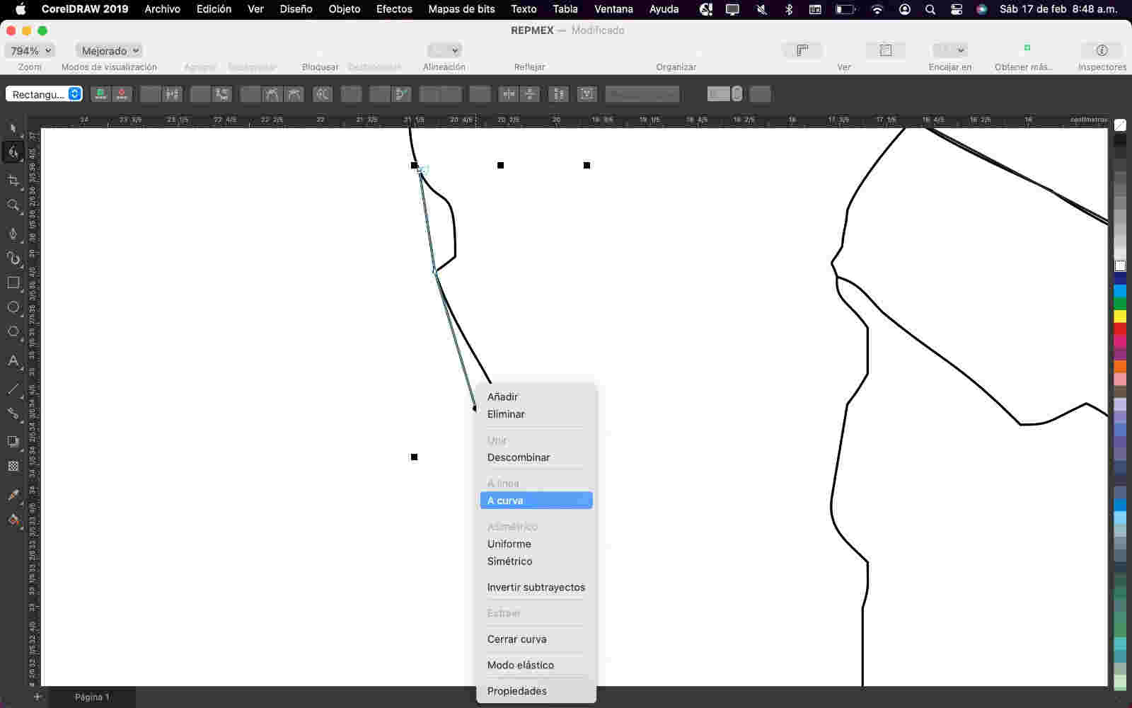
To get the curves that the image has, select the curves tool in order to manipulate the nodes that have the lines.
- By doing the same for everyone, I get the expected figure when comparing it.
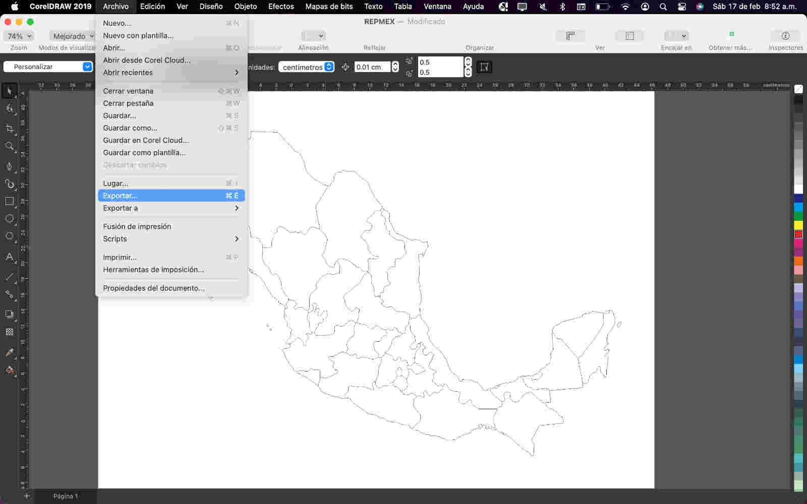
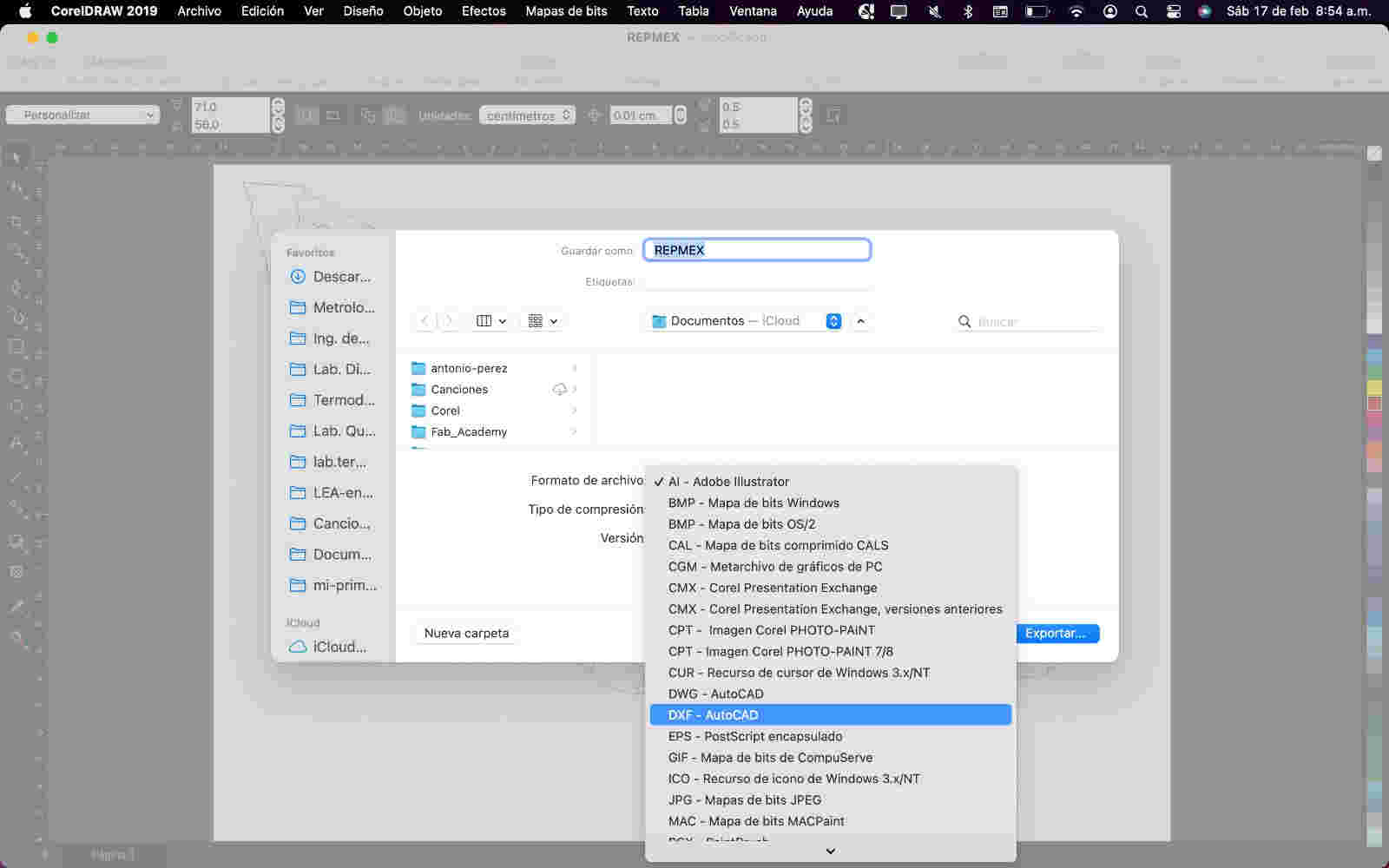
- To finish I clicked on the file>export button
- and I gave it a dxf format to send the file and be able to laser cut and that's it.


Some tutorials that explainned the CAD in 3D👨🏫
GIMP Image compressor
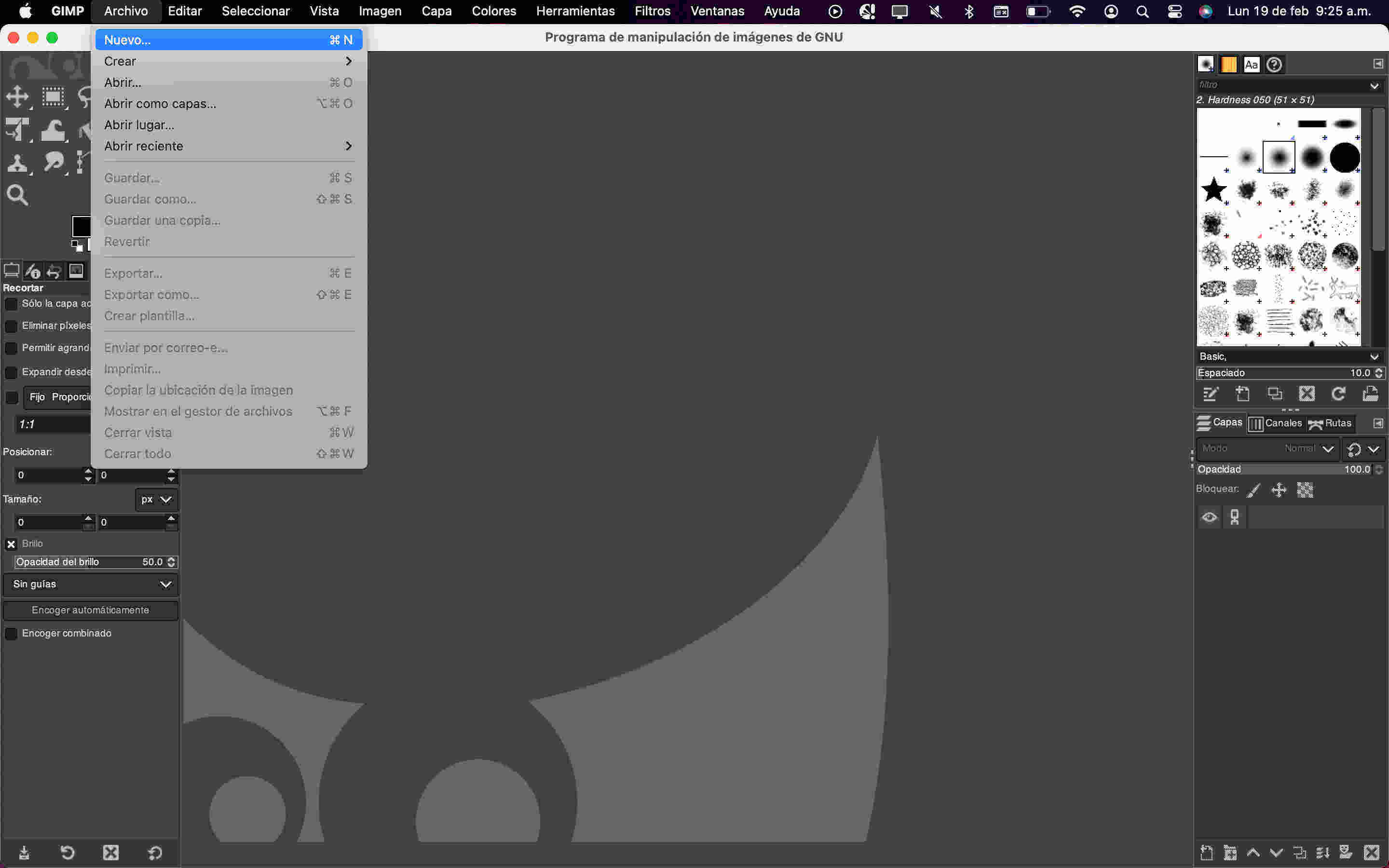
To begin, you need to open the image or file that we want to compress (upper left, file>open)
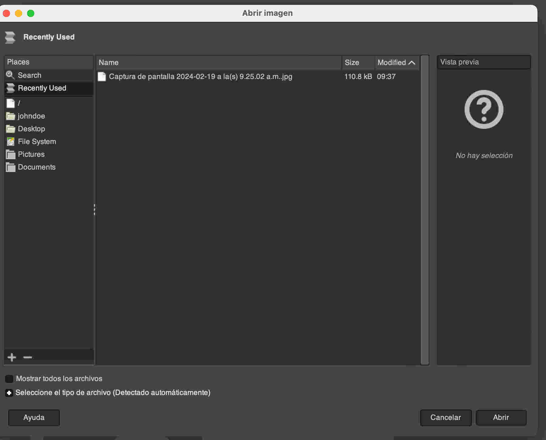
It's time to choose which image I want. Selecting the file within GIMP or I can drag it from the finder to be faster and not waste so much time searching file by file
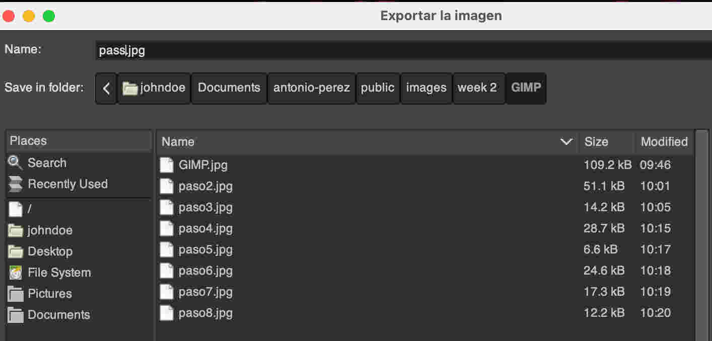
To save me a lot of time saving images one by one. What I did was name the file so that it is already in my code and save it in a folder where all the images are together
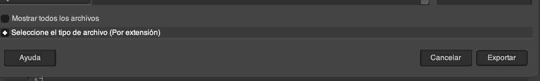
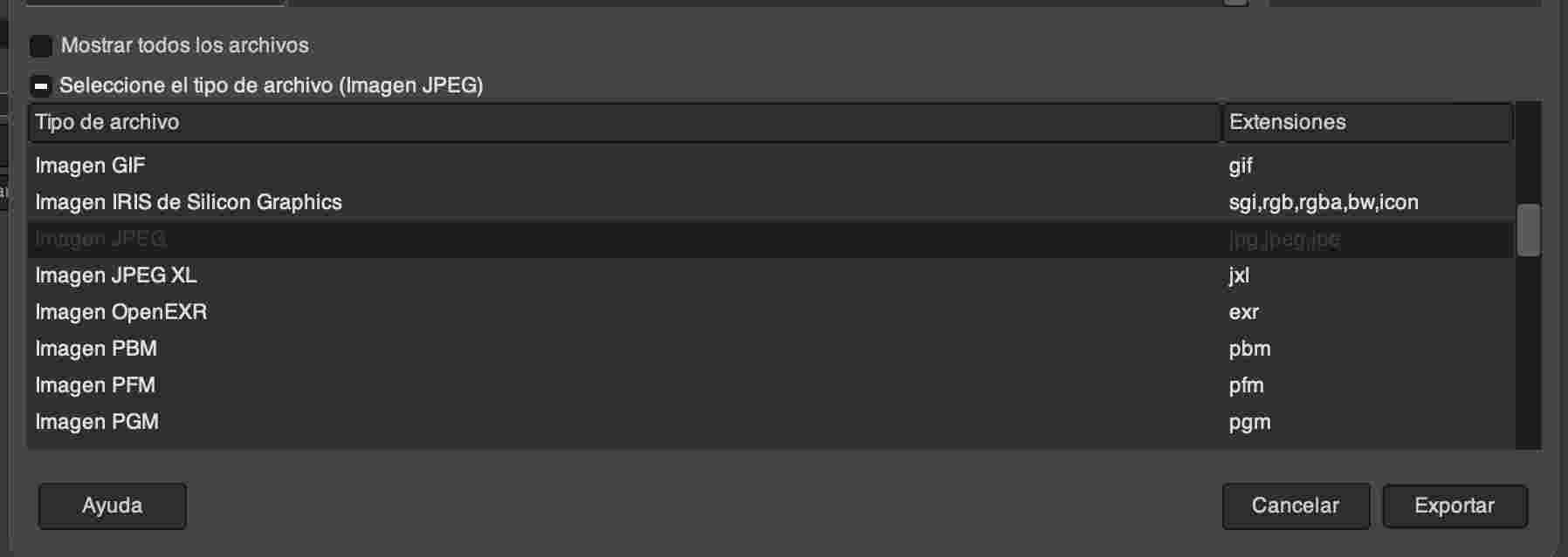
Select the type of file I want by extension (bottom bar) to obtain any type of file such as; gif, png, etc. In my case I used the jpg for the image
click the export button
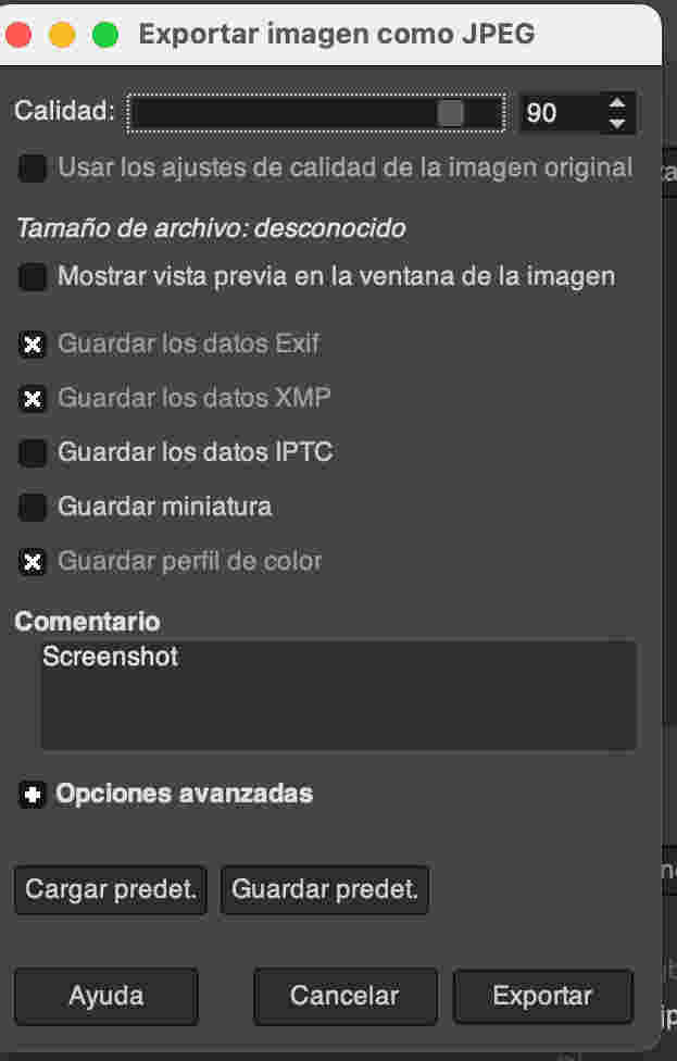
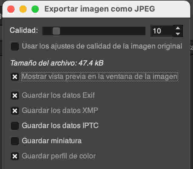
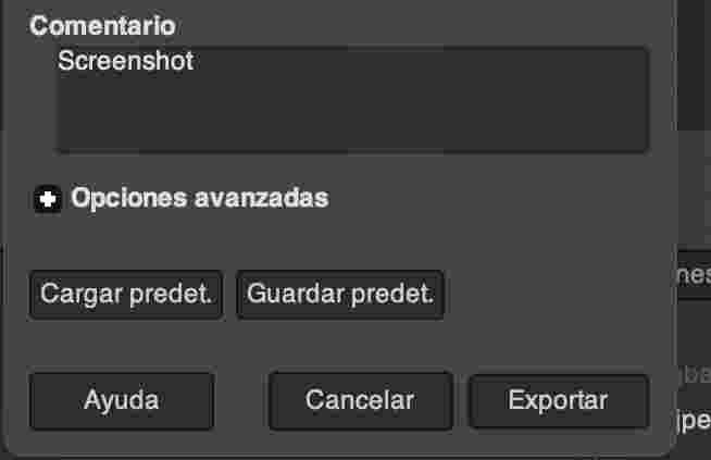
Open a new window after clicking export, in that window you can edit what quality I want my image.
Open a new window after clicking export, in that window you can edit what quality I want my image. By clicking on the option to show preview in the image window, it will appear how heavy the image is.The last step is to click on the export button Note: I noticed that you can add comments to the image, that is very good to be able to recognize the image more easily.