Industrial-Grade PCB Fabrication
A comprehensive documentation of the professional workflow for creating precision printed circuit boards, from milling to functional testing
Production Soundtrack
PCB Engineering Fundamentals
Printed Circuit Board Technology
PCBs are essential in modern electronics, providing structure and connectivity between components through copper traces.In our lab, we use CNC milling for quick prototyping on single-sided FR-4 boards. This method is ideal for testing and learning the basics of circuit design and production.
This approach allows us to deeply understand electronic fabrication—from design to execution—laying the groundwork for more advanced projects such as multilayer circuits or scaled production.

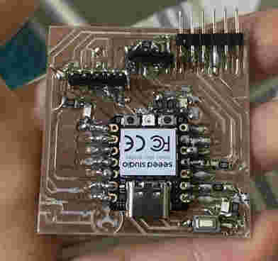
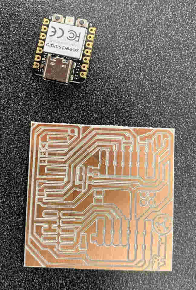
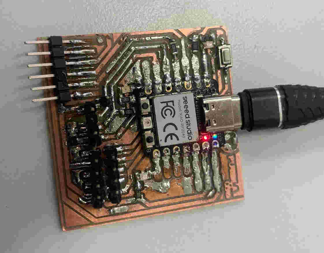
Figure 2: Fully assembled PCB with all components soldered.
Precision Milling Equipment
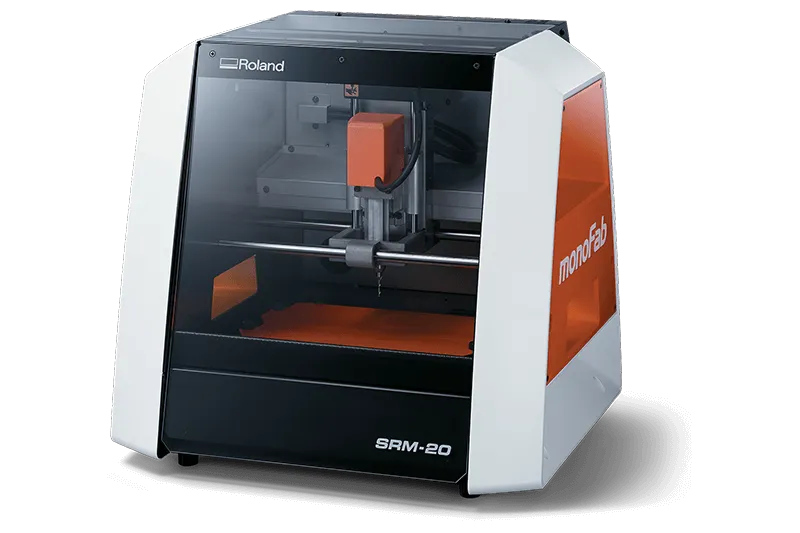
The Roland SRM-20 provides industrial-grade accuracy for prototyping and small batch production
Roland SRM-20 Technical Specifications
System Overview
The Roland SRM-20 is a benchmark desktop milling machine offering professional results in a compact footprint. Its rigid aluminum frame and precision ball screws provide exceptional accuracy for PCB prototyping.
Key advantages for electronics production:
- 20,000 RPM spindle with speed control
- 0.001mm/step microstepping drivers
- Automatic tool length measurement
- Dedicated PCB milling presets
- Compact footprint with 203×152mm work area
Technical Specifications
| Parameter | Specification |
|---|---|
| Work Area | 203.2 × 152.4 × 60.5 mm (X,Y,Z) |
| Positioning Accuracy | ±0.01 mm/100 mm |
| Repeatability | ±0.005 mm |
| Maximum Speed | 1,800 mm/min |
| Spindle Speed | 3,000 - 7,000 RPM (standard) |
| Tool Diameter | 0.2 - 6.35 mm |
| Software Interface | VPanel control software, MODS workflow |
PCB Fabrication Workflow
Professional-grade process from design to functional board
Manufacturing Process Documentation
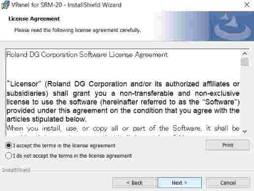
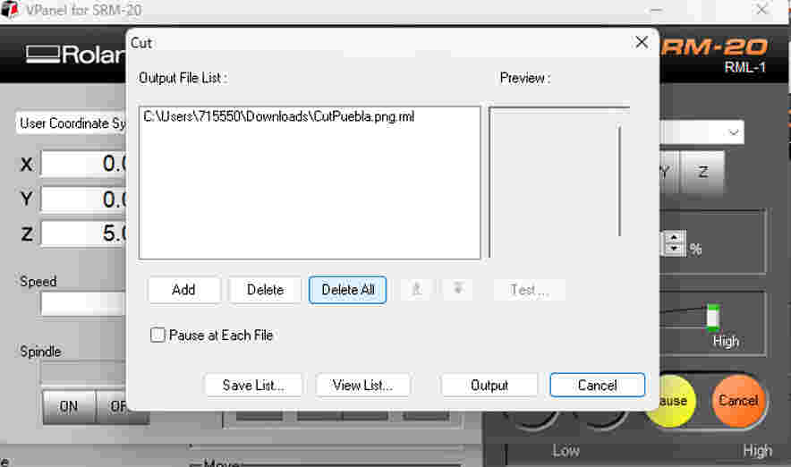
VPanel software installation and configuration
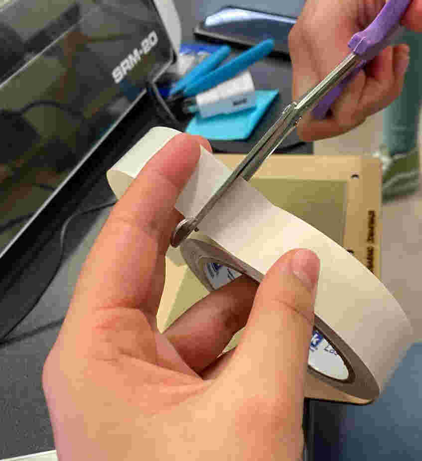
Preparing sacrificial bed with double-sided tape
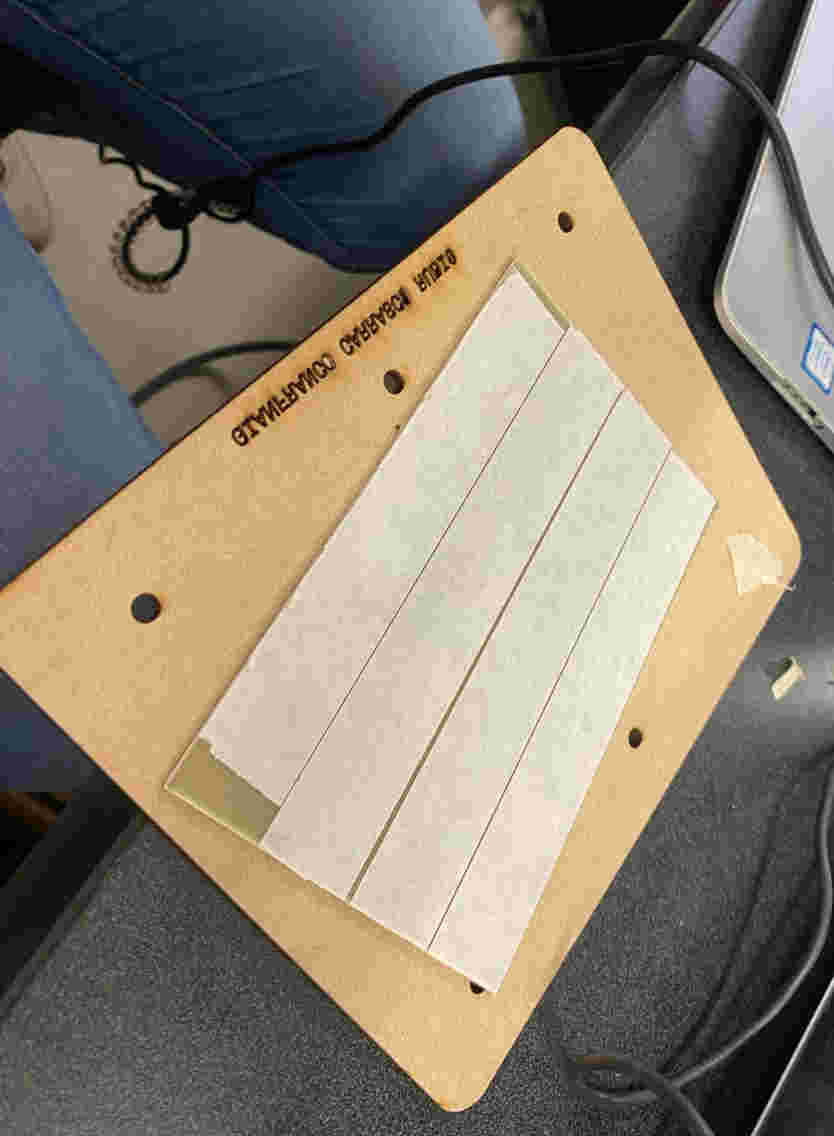
Securing copper board with tape
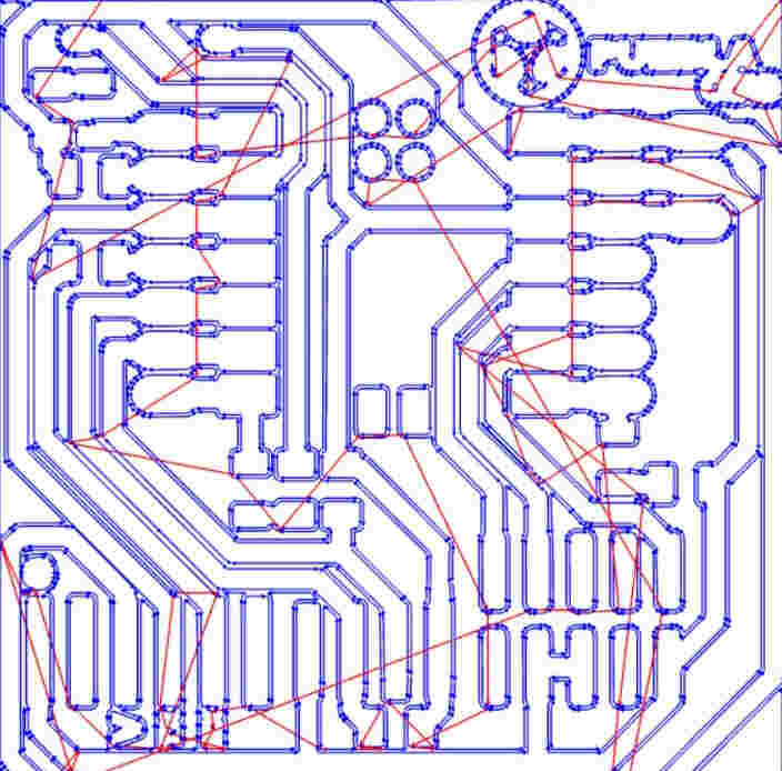
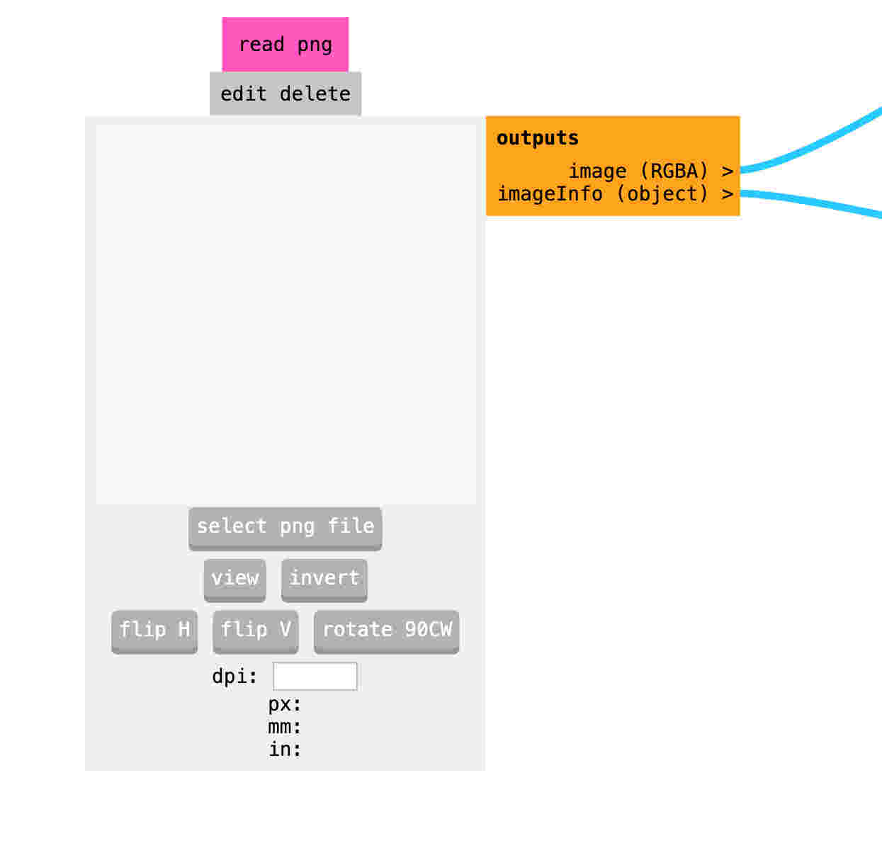
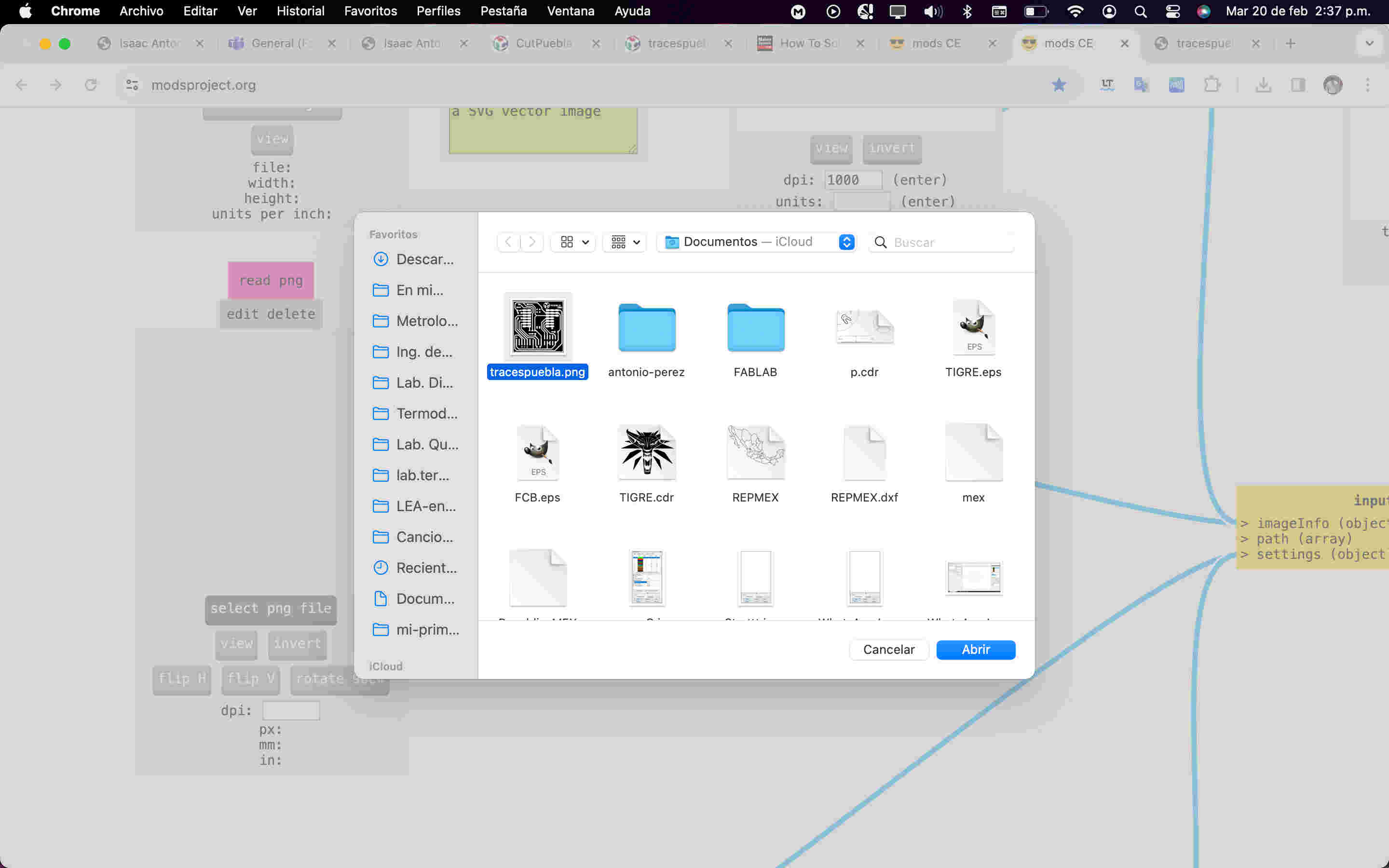
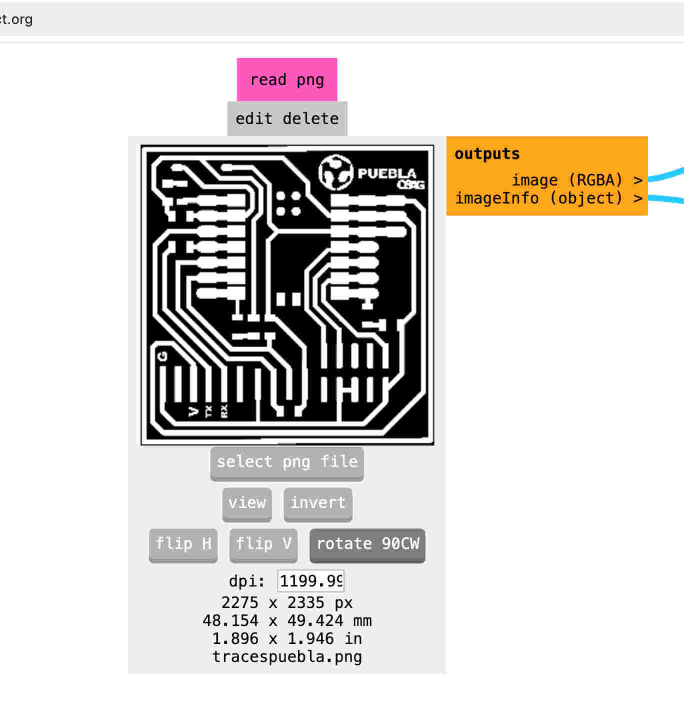
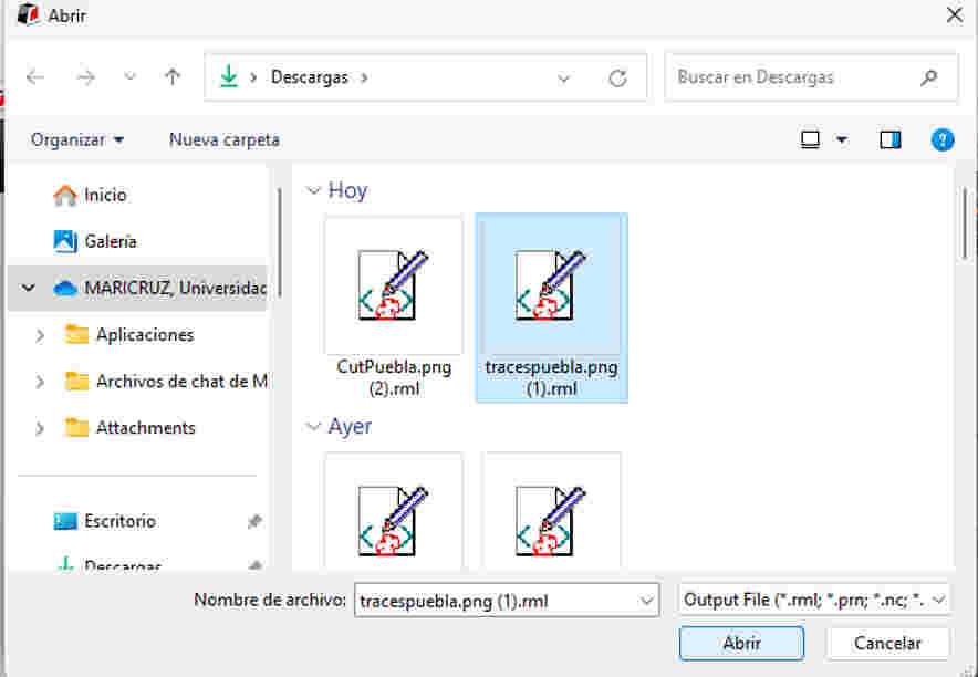
Designing PCB traces (PNG format)
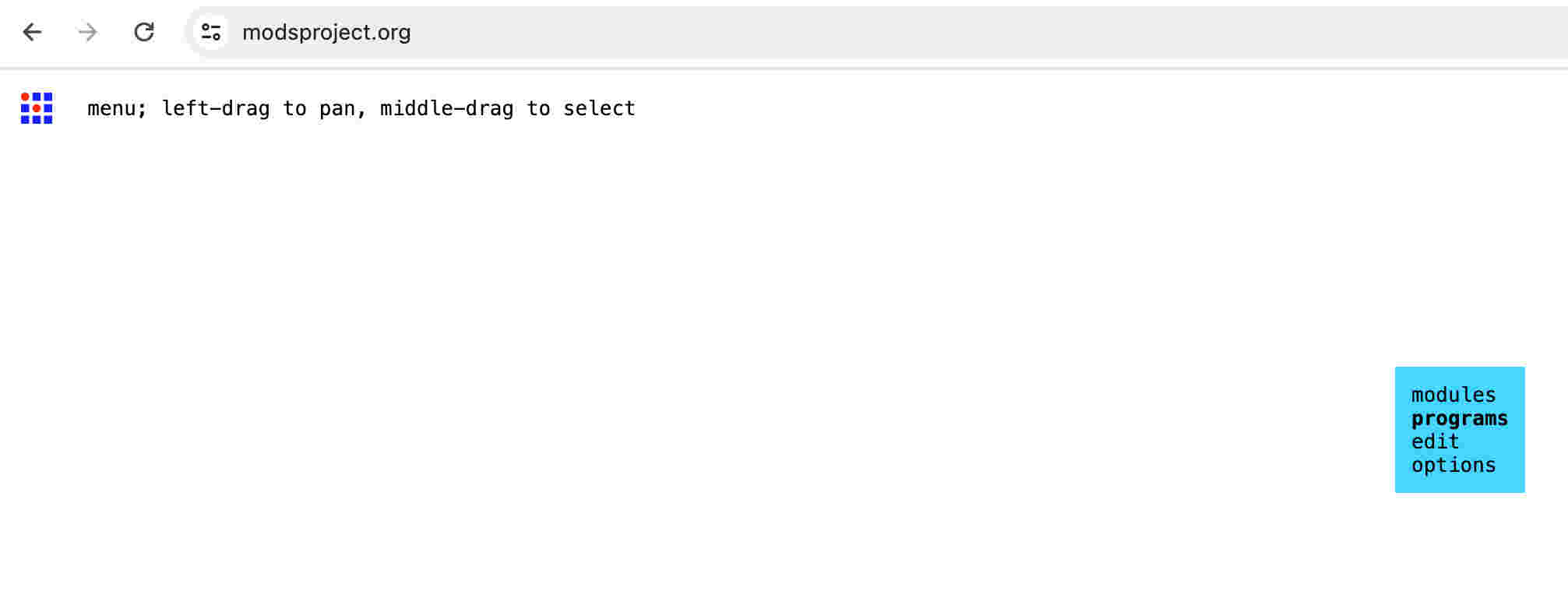
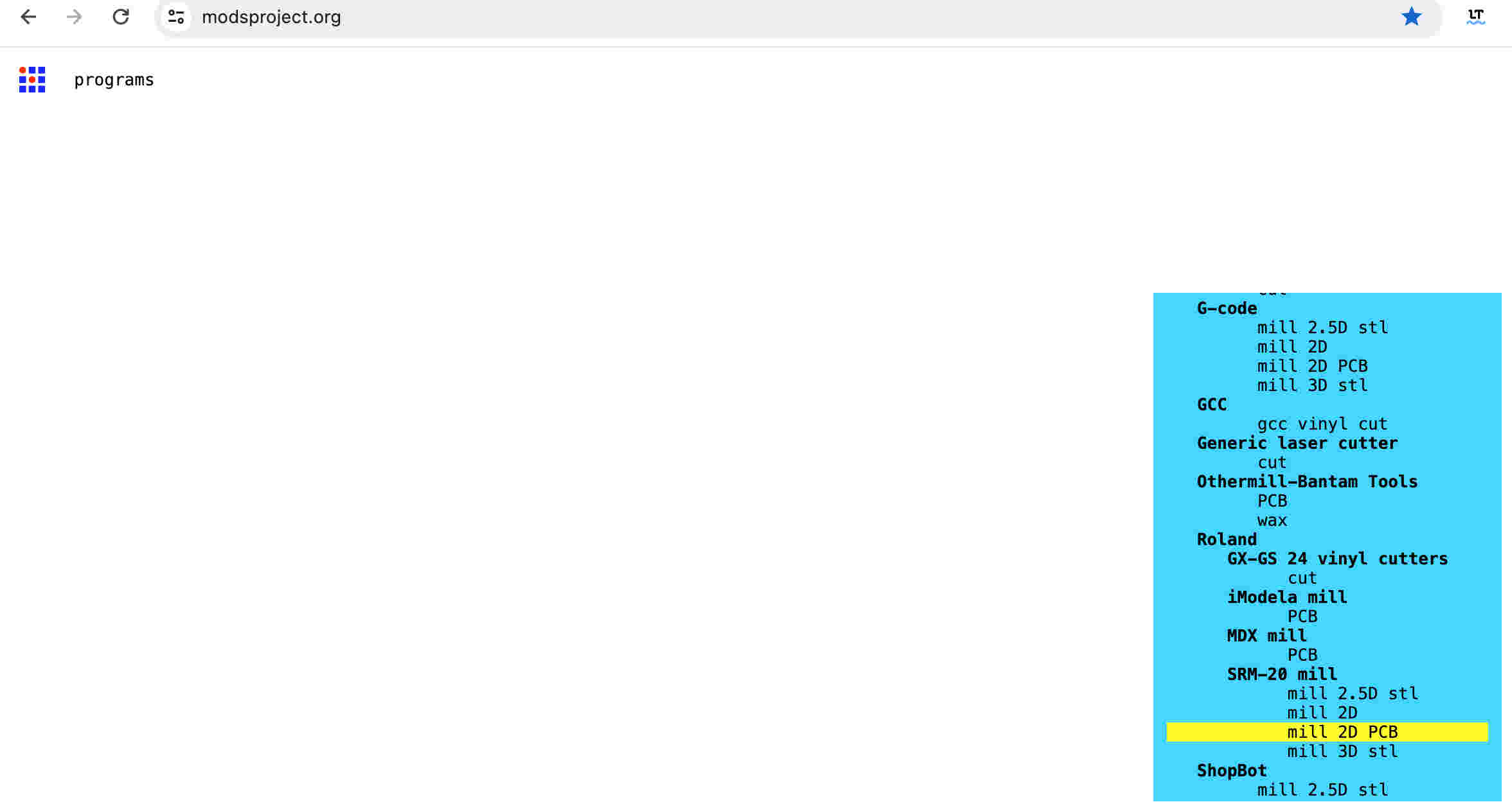
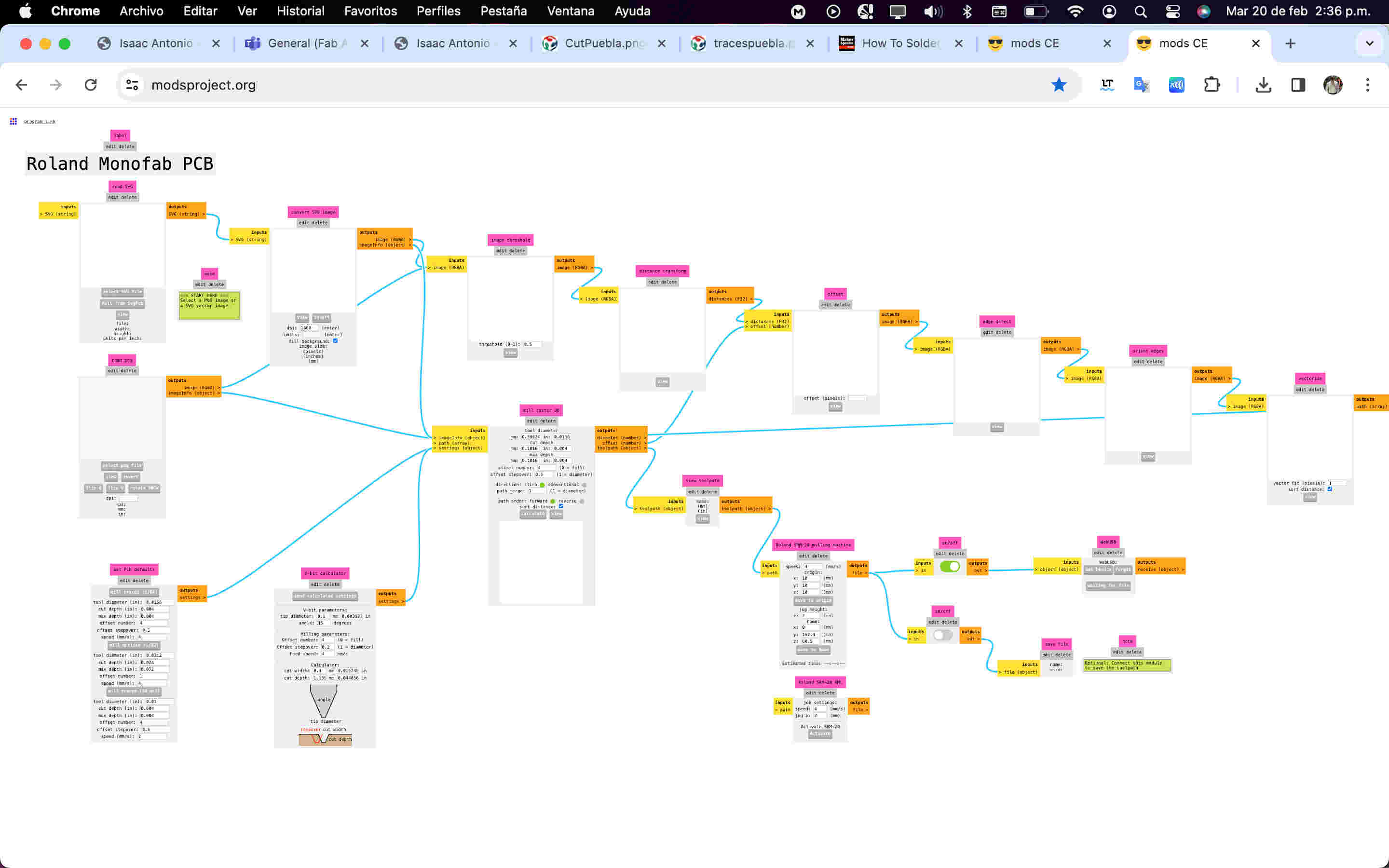
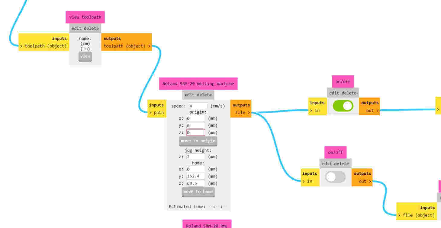
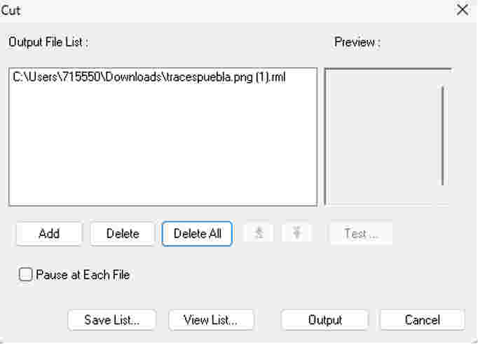
Generating toolpaths with MODS
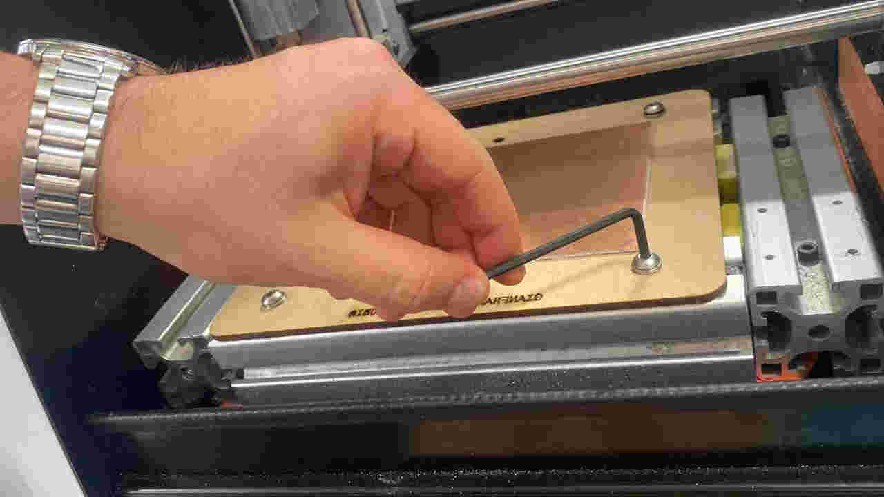
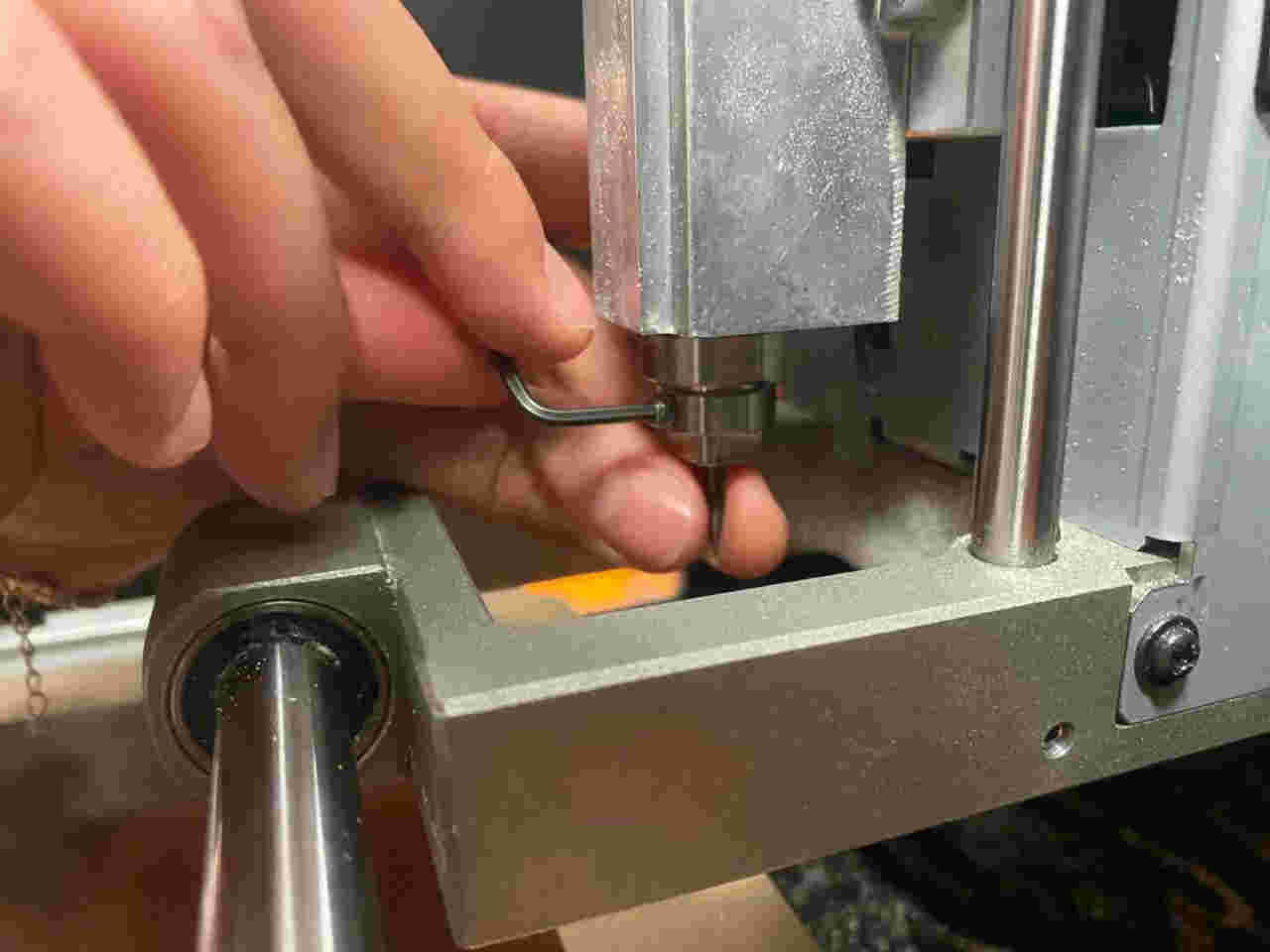
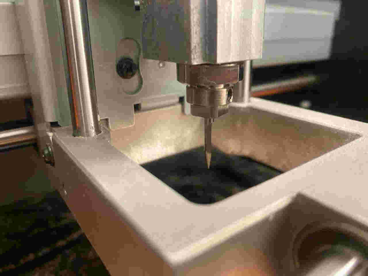
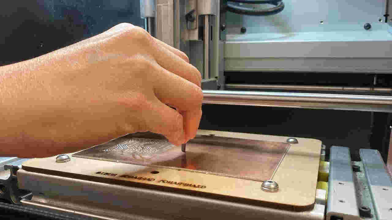
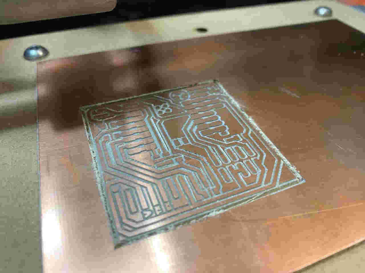
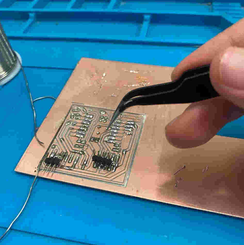
Precision milling in progress
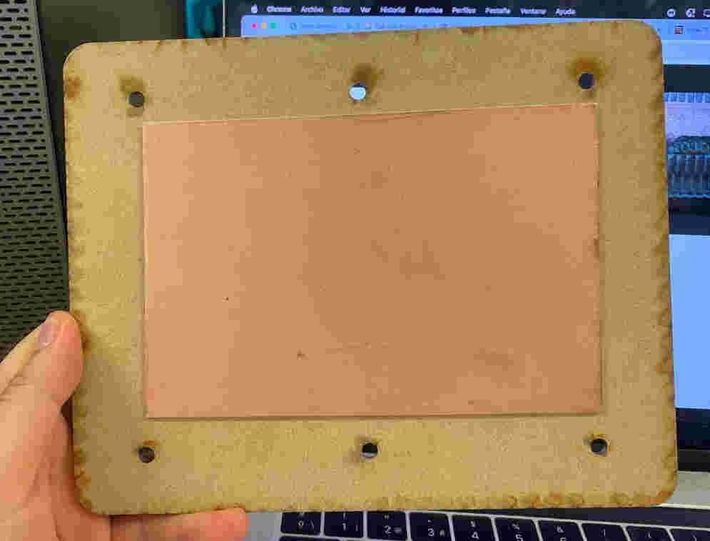
PCB milled and ready for soldering
PCB with components soldered
Completed functional PCB
Completed functional PCB
Completed functional PCB
Completed functional PCB
Completed functional PCB
Completed functional PCB
Completed functional PCB
Completed functional PCB
Completed functional PCB
Completed functional PCB
Completed functional PCB
Completed functional PCB
Completed functional PCB
Completed functional PCB
Completed functional PCB
Completed functional PCB
PCB Manufacturing Process
Click on each step to view detailed information about the manufacturing process
Installed and configured VPanel control software, establishing USB connection to the SRM-20. Verified machine communication and homing functionality before proceeding with material setup.
Fabricated sacrificial MDF bed with high-tack double-sided tape for secure copper plate adhesion. Verified flatness using precision straightedge before final mounting to machine bed.
Mounted copper-clad FR4 substrate (100×80mm, 1oz copper) to sacrificial bed using uniform pressure application. Confirmed complete adhesion across entire surface to prevent vibration during milling.
Processed instructor-provided PCB template (600dpi PNG) through MODS workflow, generating optimized toolpaths for 0.2mm V-bit. Verified trace isolation and clearance in preview mode.
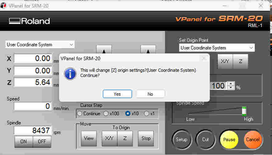
Configured MODS parameters: 0.1mm cut depth, 3.6mm/sec feed rate, 7000 RPM spindle speed. Generated separate toolpaths for traces (4 offsets) and board outline (full depth cut).
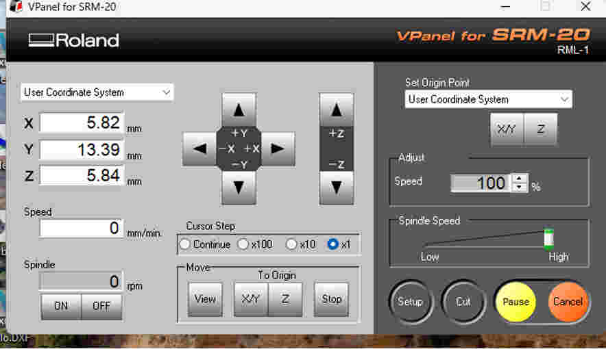
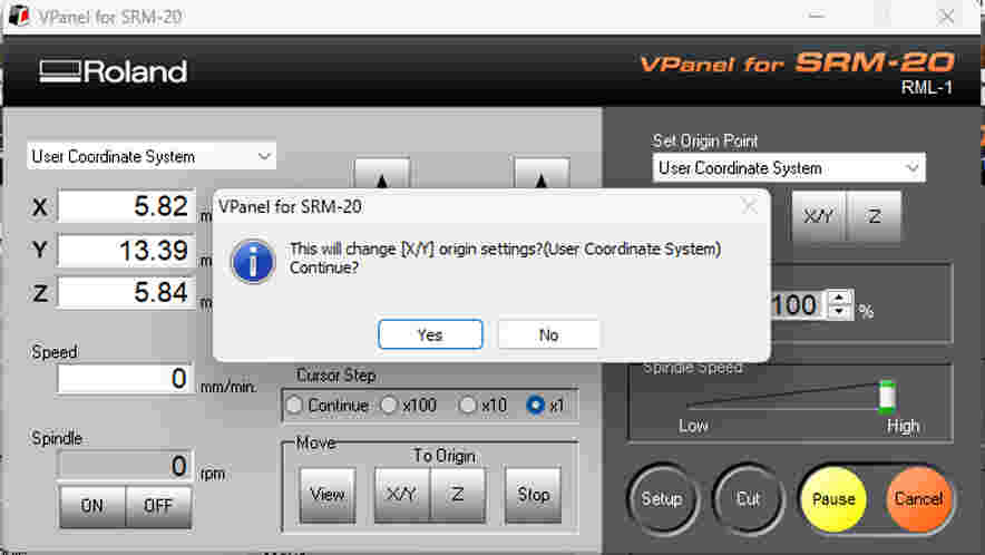
Established X/Y origin at board corner using edge-finding technique. Set Z-axis origin with 0.001mm precision using paper shim method. Performed dry run verification before material engagement.
Monitored initial trace milling passes, adjusting feed rate as needed for optimal copper removal. Completed outline cut with final depth verification to ensure clean board separation.
Deburred board edges with fine abrasive. Cleaned copper surfaces with isopropyl alcohol. Conducted continuity testing on all traces using multimeter before proceeding to assembly.
Precision Assembly
Component integration and quality verification
Professional Soldering Techniques
Assembly Methodology
Employed industry-standard soldering techniques using temperature-controlled station (340°C) with ESD-safe practices. Followed IPC-A-610 Class 2 standards for prototype work:
- Component placement sequence: Lowest profile to highest
- Dual-phase soldering: Tack solder then final joint completion
- Visual inspection under 10x magnification
- Continuity verification after each component
Special attention given to XIAO RP2040 microcontroller, ensuring proper alignment and pin-to-pad registration before soldering.
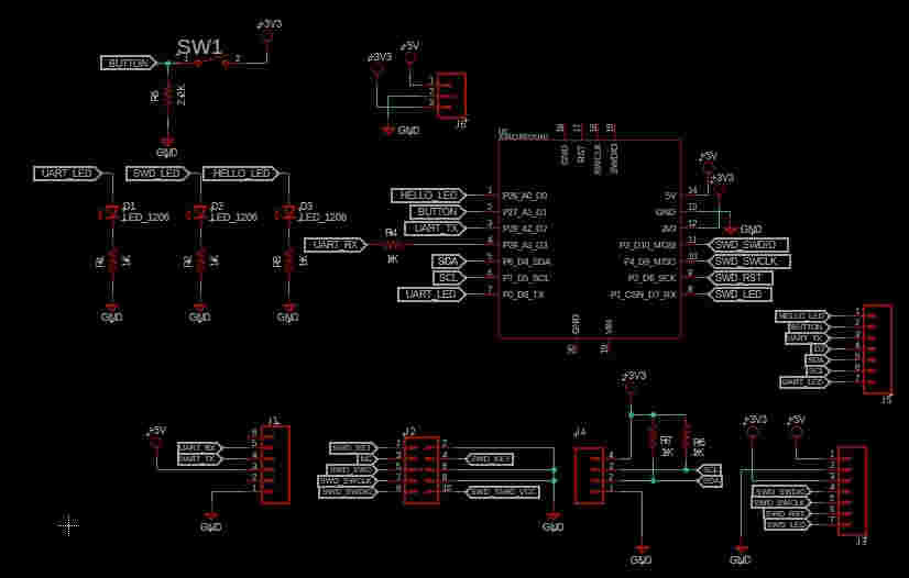
Component placement reference
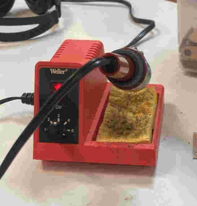
Temperature-controlled soldering station
Precision component placement

Completed assembly
Process Documentation
Bill of Materials
| Component | Qty | Spec |
|---|---|---|
| XIAO RP2040 | 1 | Seeed Studio |
| Resistor 10kΩ | 1 | 0805 SMD |
| Resistor 499Ω | 2 | 0805 SMD |
| LED Green | 1 | 1206 SMD |
| LED Red | 1 | 1206 SMD |
| Tact Switch | 1 | 6×6mm TH |
Functional Verification
Board passed all functional tests with expected LED response to button input
Firmware Integration
Validating hardware functionality through software
Embedded Software Development
Test Program Architecture
The validation firmware implements a simple finite state machine to test all critical board functions:
- Digital input (button with pull-up resistor)
- Digital output (LED drive circuits)
- Power regulation stability
- Signal integrity across traces
Program logic flows through these states:
- Initialize all I/O pins
- Enable green LED (power indicator)
- Monitor button input
- Toggle red LED on button press
- Debounce input for reliable operation
XIAO RP2040 Toolchain
Development environment configuration:
- Arduino IDE 2.3.2
- Seeed Studio RP2040 board package
- USB-C connection for programming
- Bootloader mode (double-tap reset)
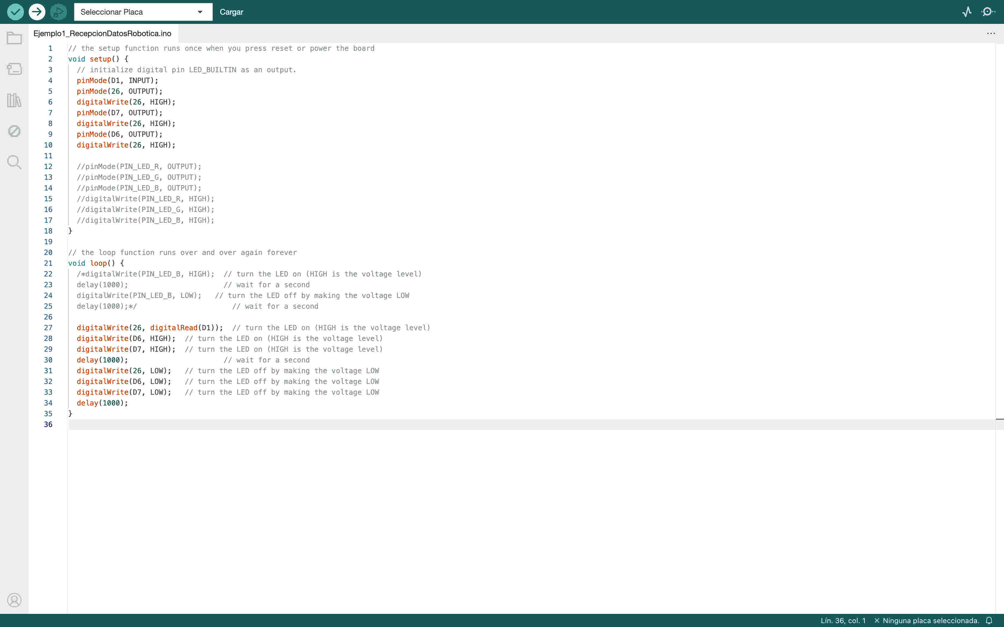 Fig. 2 - Development environment screenshot
Reference Materials
Technical documentation and project assets