Assignment Checklist
| Status | Task |
|---|---|
| Linked to the group assignment page | |
| Reflected on group work on your individual page | |
| Explained how you created your parametric design | |
| Documented how you made your press-fit construction kit | |
| Documented how you made something with the vinyl cutter | |
| Included your original design files | |
| Included hero shots of your results |
Group Assignment
Work Soundtrack
"Rubicon" by Peso Pluma is my favorite song on this playlist
Why is Computer Controlled Cutting Important?
Computer controlled cutting is essential for its precision, efficiency, and versatility across industries. It enables the fabrication of complex designs, ensures reproducibility, and enhances safety through automation.
What is Kerf?
Understanding Kerf
The kerf in CNC laser cutting refers to the material width removed by the laser beam during a cut. This seemingly small value — typically between 0.1mm to 0.5mm — becomes essential when designing for precision and fit.
Why is it important? Kerf varies based on:
- Material (MDF, acrylic, etc.)
- Laser power and speed
- Focus and beam width
- Machine calibration
To determine our kerf values, we ran tests using 3mm MDF and 3mm acrylic. We designed a row of rectangles with laser-cut separations and applied this formula:
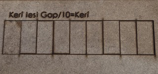
Kerf = (Original Length – Measured Length) / Number of Cuts
Results:
- MDF kerf ≈ 0.12mm (more burn and fiber loss)
- Acrylic kerf ≈ 0.06mm (cleaner, melted edges)
With these values, we adjusted our parametric design in Fusion 360 so that slot and tab dimensions compensated for material loss. This ensured clean, press-fit joints without glue.
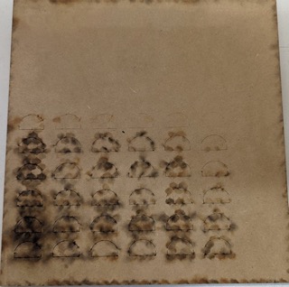
Measuring Kerf
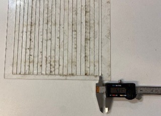
By sliding all the pieces to one side, we created a gap that we can measure using a caliper. This means that the cut can be calculated by dividing the total space by the number of cuts made.
Laser Cutting Process
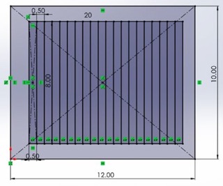
I designed a square with rectangles of the same size to conduct the laser test.
I tested the design and its kerf to ensure precise adjustments in the laser cutting process.
I performed a kerf test to measure the cutting width of the laser cutter.
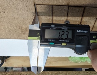
These are the millimeters removed by the kerf during cutting.
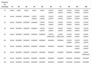
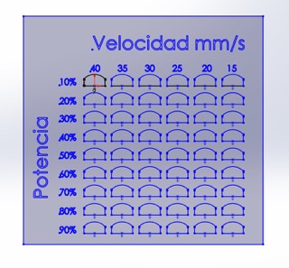
I used different power settings to determine the best one for laser engraving or cutting.
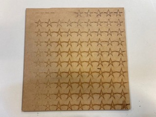
Testing laser power on 3 mm MDF to optimize engraving and cutting.
Testing laser power on 3 mm MDF to optimize engraving and cutting.
Testing laser power on 3 mm MDF to optimize engraving and cutting.
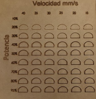
This is the result of the cut with the given speed and power settings.
Laser Cutter Specifications

CFL-CMA1080K
Technical Specifications
| Area | 1.00 x 0.80 meters |
| Table | Honeycomb or rod |
| Accessory | Double Tube |
| Cutting speed | 0–36,000 (min/mm) |
| Engraving speed | 0-64000 (min/mm) |
| Power | 100 Watts |
| Cutting thickness | 0–25 mm |
| Resolution | Up to 4000 DPI |
| Motion accuracy | 0.01 mm |
Laser Focus Mechanism

| Component | Function |
|---|---|
| Unfocused Laser Beam | The initial laser beam generated from the laser source, wider and less concentrated |
| Focus Lens | Focuses the laser beam into a smaller, more potent point |
| Focal Distance | Determines where the laser beam is highly concentrated |
| Laser Nozzle | Guides the laser beam and eliminates residues |
| Focused Laser Beam | Amplified intensity beam after passing through the lens |
| Focal Point | Where maximum concentration occurs for cutting/engraving |
| Focus Depth | Span where light persists within a confined point |
A distance of 5 mm from the nozzle is advised for achieving optimal focus. Occasionally, adjusting the focus below the material surface can manage the cutting shape, particularly with thicker materials.
Laser Cutting Process
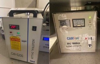
The button is activated from the power source to start the system.
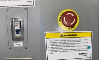
Press the red button to turn on the machine, then activate another button to start its operation.
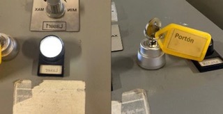
I pressed the white button to supply power to the laser machine and turned the key to grant authorization.
I adjusted the material in the designated area to ensure proper placement and processing.
Material Compatibility
Materials You Can Cut
| Material | Cut | Engrave |
|---|---|---|
| Paper | ||
| Cardboard | ||
| Foam | ||
| Leather | ||
| Cork | ||
| MDF | ||
| Wood | ||
| Plastic | ||
| Acrylic | ||
| Metal |
Materials You CAN'T Cut
| Material | Reason |
|---|---|
| PVC (Poly Vinyl Chloride) | Emits toxic chlorine gas when cut |
| ABS | Melts and can catch fire, emits hydrogen cyanide |
| HDPE/milk bottle plastic | Melts, becomes gooey, and catches fire |
| PolyStyrene Foam | Catches fire quickly and burns rapidly |
| Epoxy | Creates toxic fumes like cyanide when burned |
| Fiberglass | Produces toxic fumes similar to epoxy |
| Foodstuff (meat, cookies, bread) | Not suitable for laser cutting |
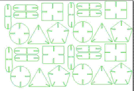
Prototype parametric design
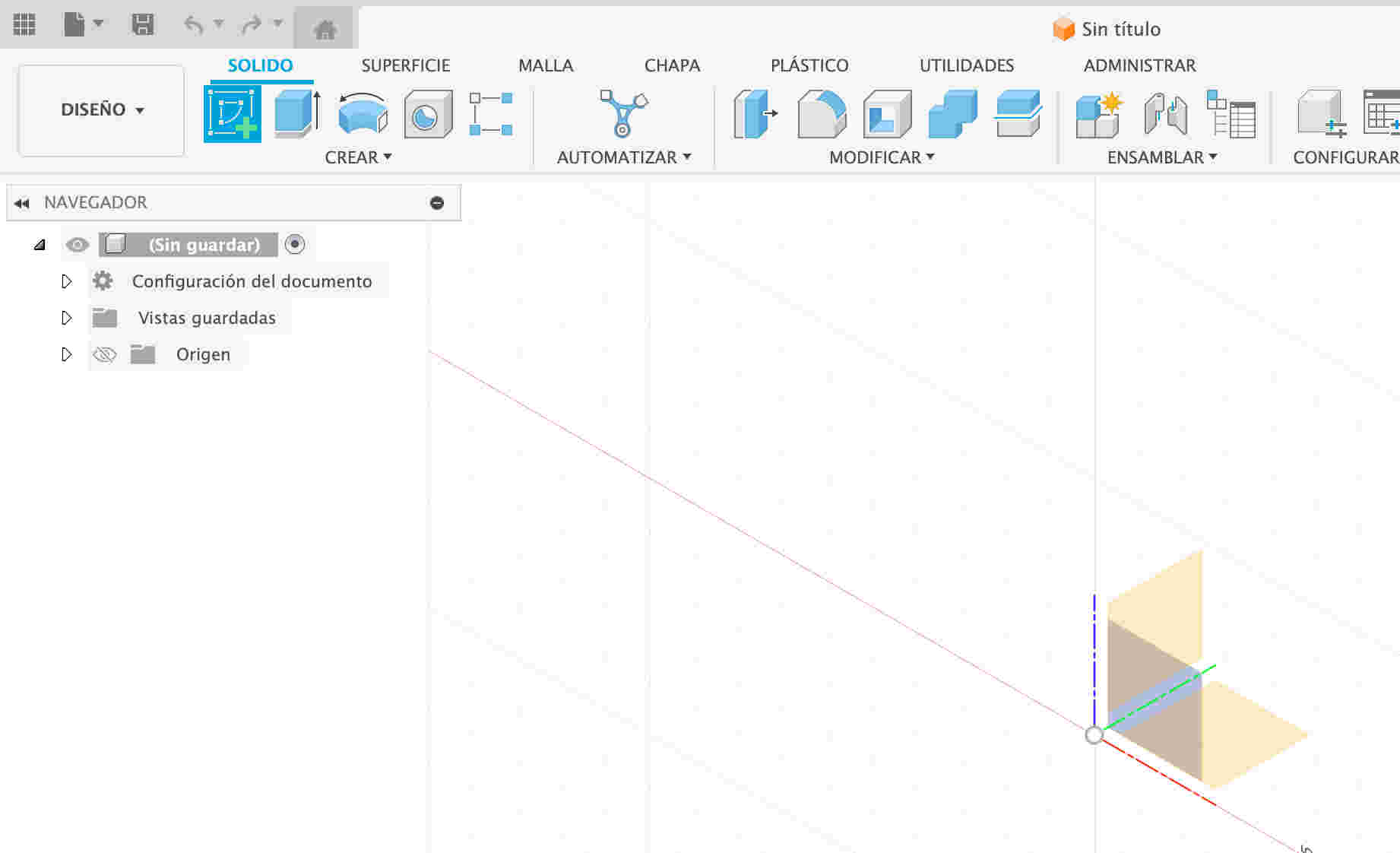
I opened Fusion 360 to begin modeling my parametric kit from scratch, setting up the foundation for an adjustable design.
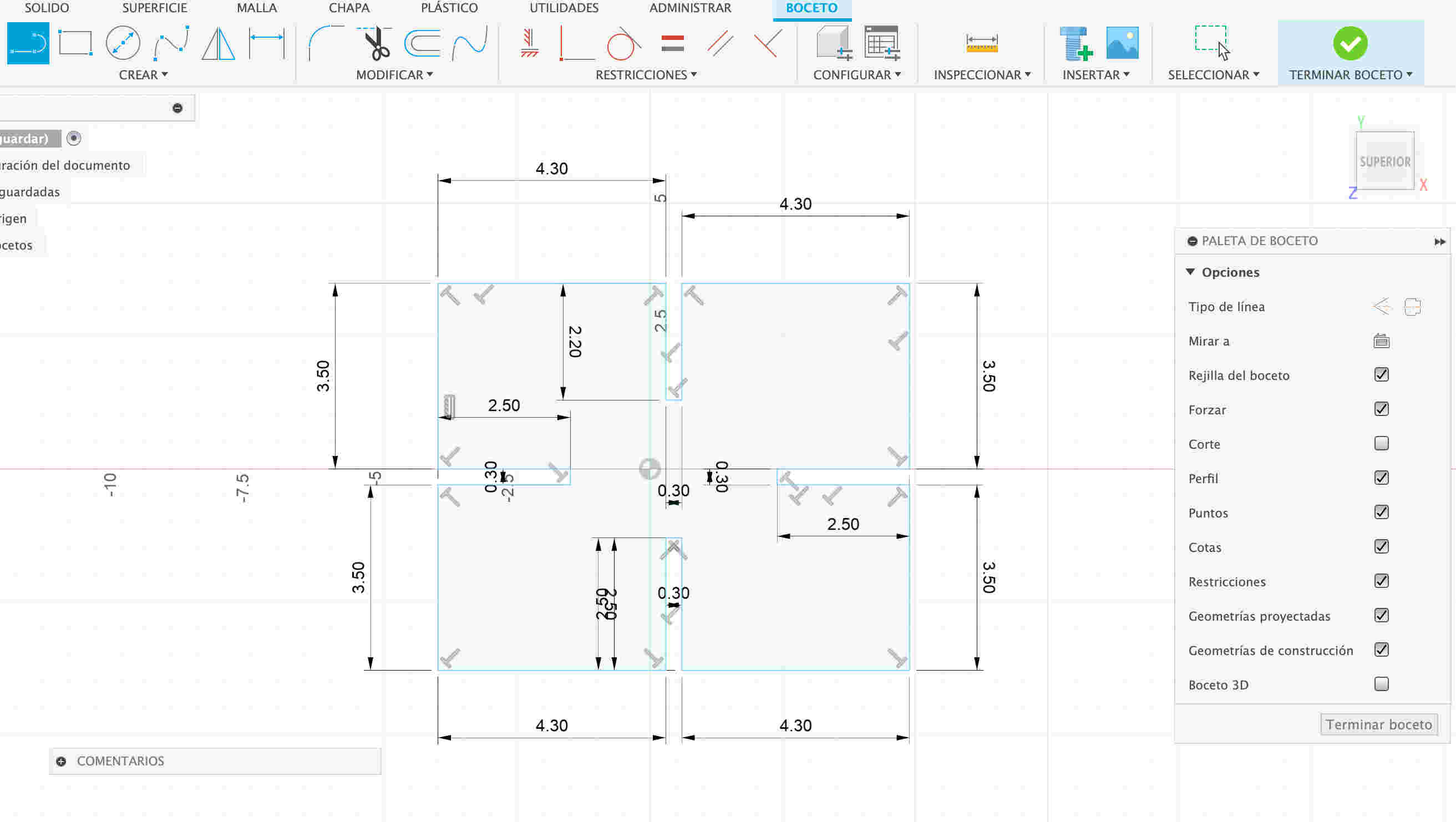
I used the line tool to draw a square, adding a 3 mm slot in the center so it can connect with another piece.
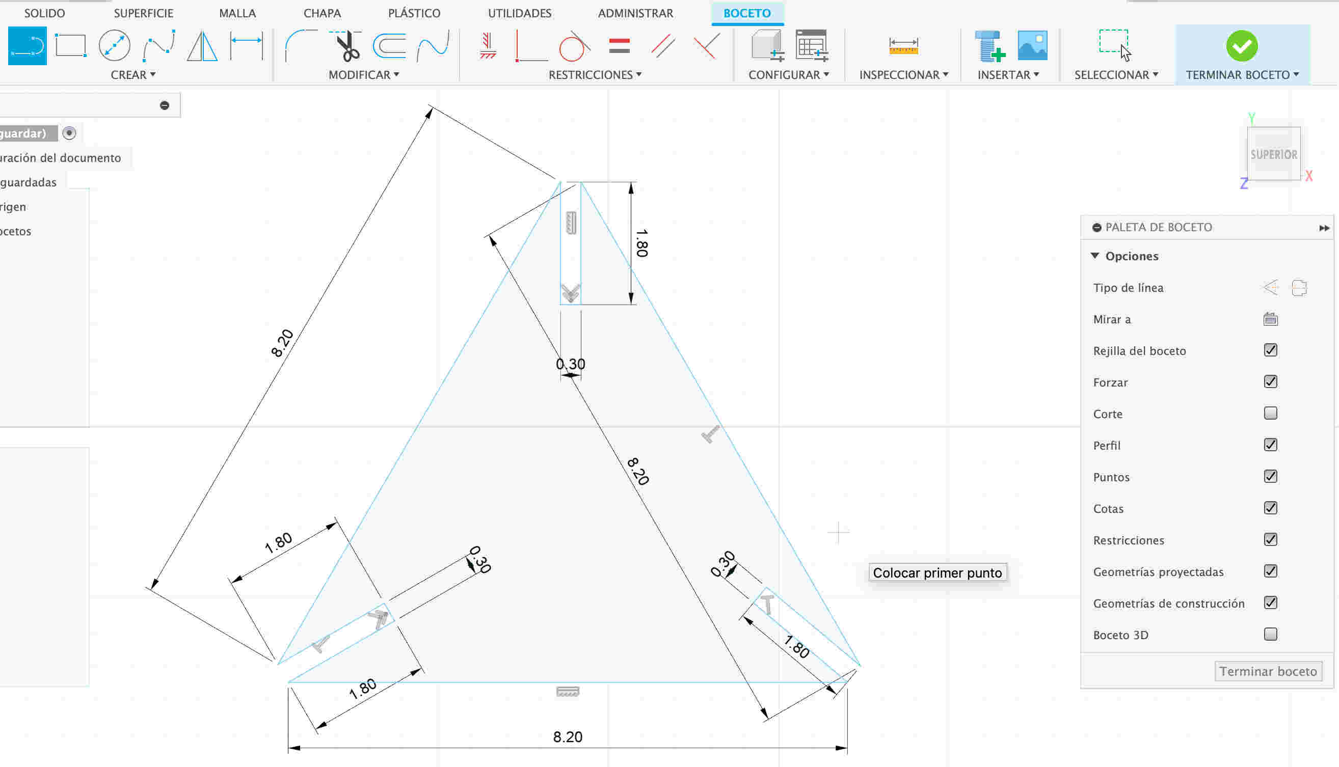
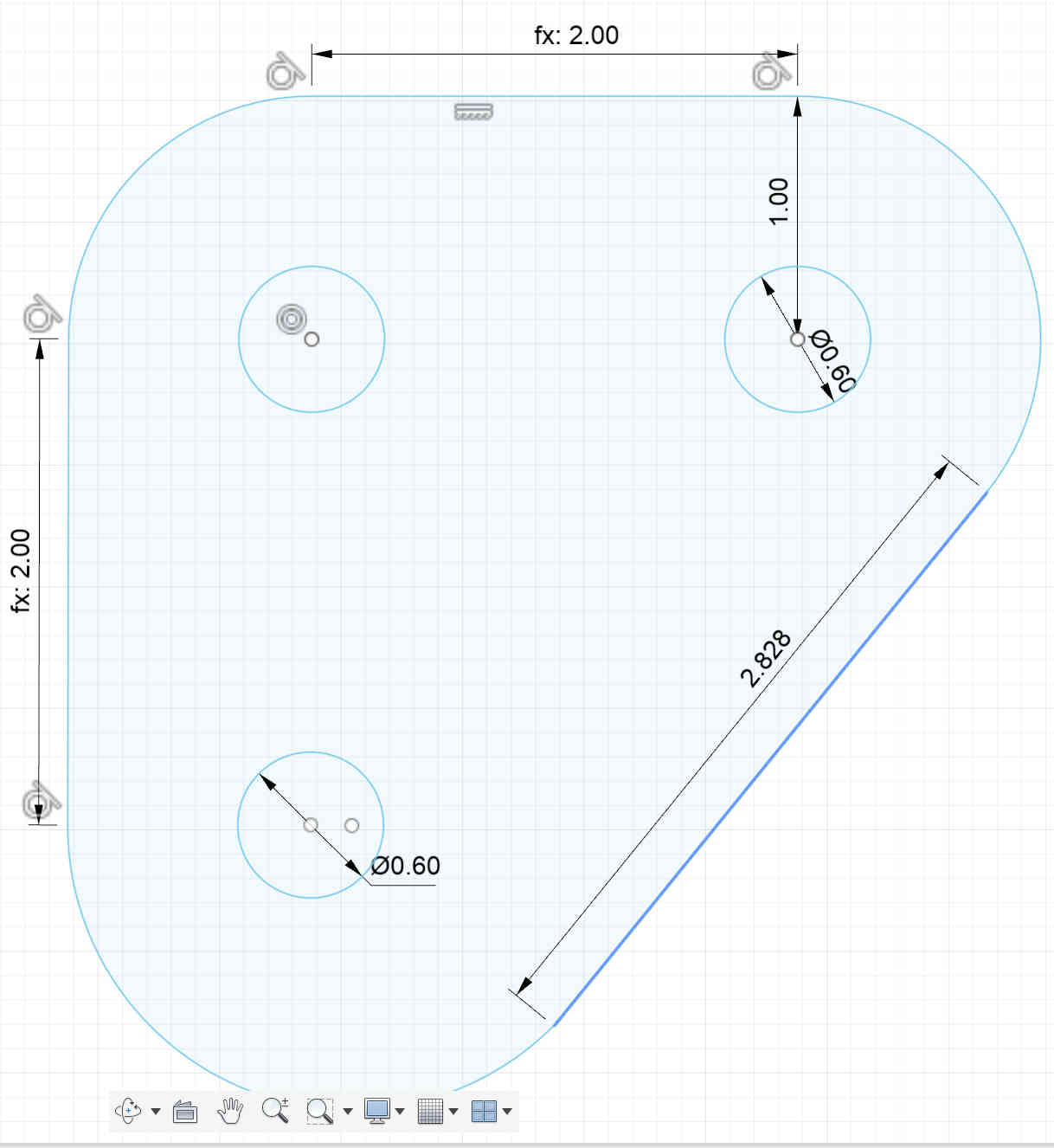
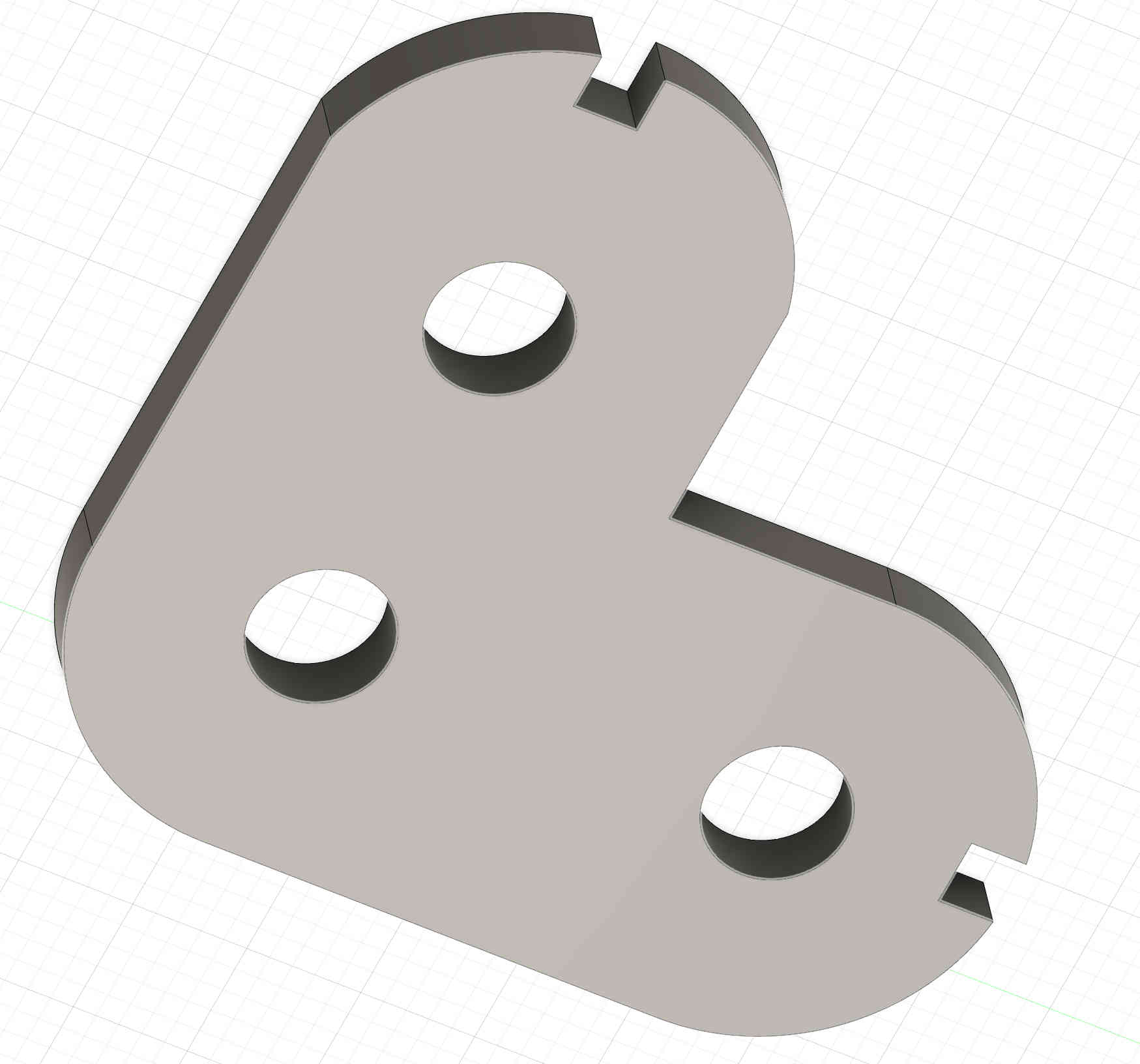
I used the line tool to draw a triangle, adding 3 mm gaps at the center of the square to allow it to connect with another piece.
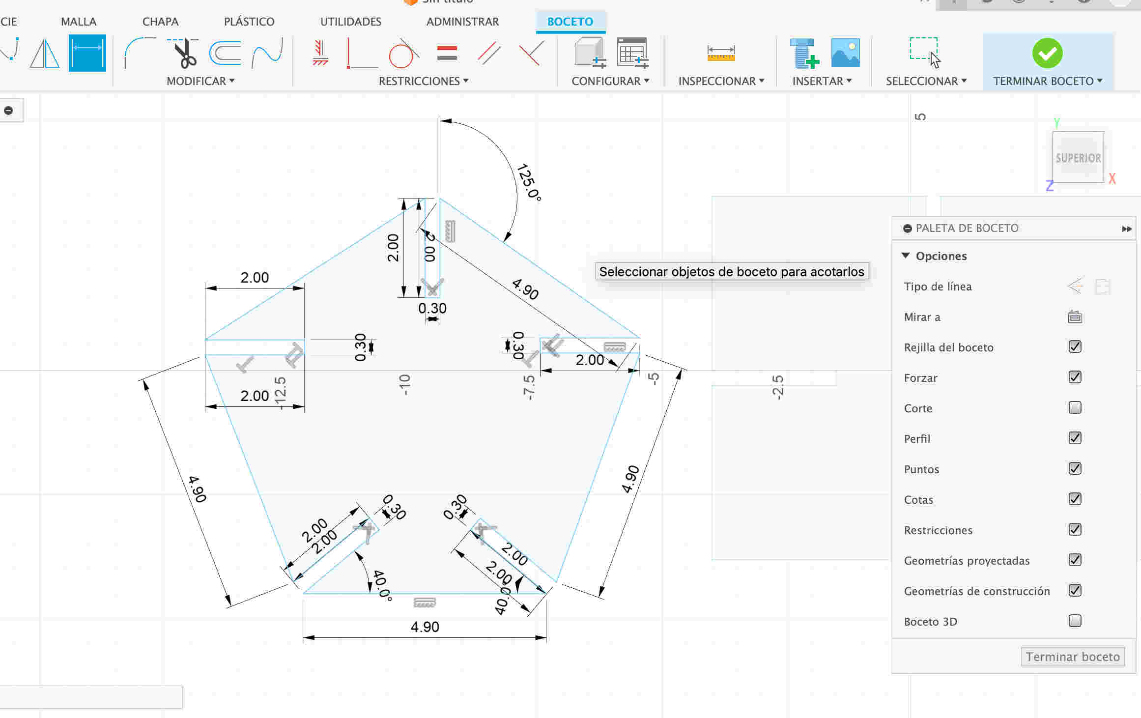
I used the line tool to draw a pentagon inside a square, leaving 3 mm gaps in the center to allow it to connect with another piece.
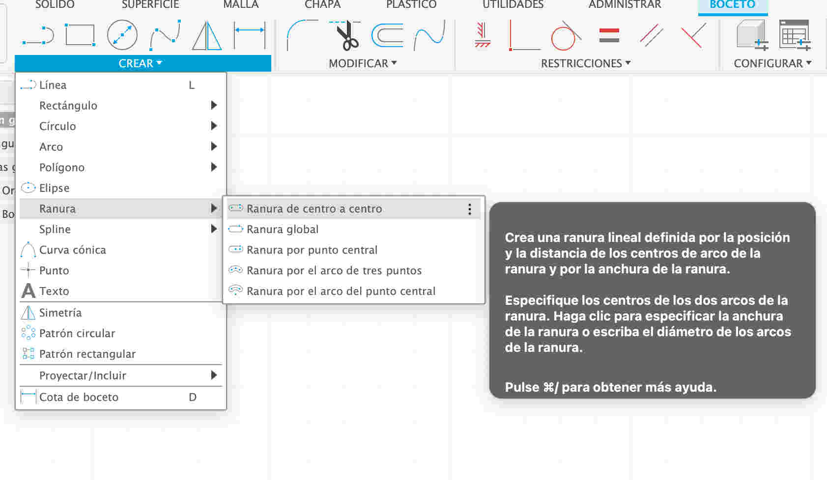
I clicked on the "Create" option and selected "Slot", then chose "Center to Center Slot" for greater precision in the design.
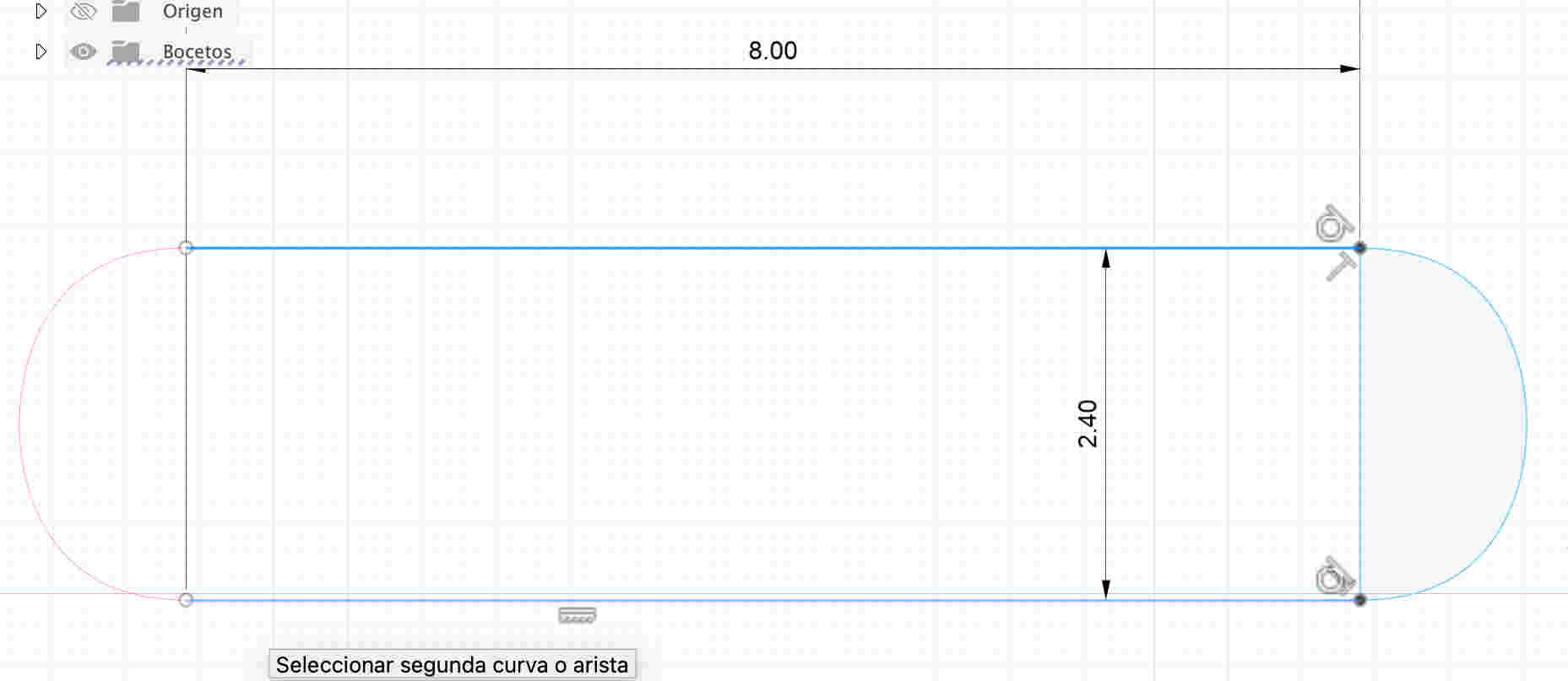
I clicked on the plane to draw a borderless rectangle, serving as a clean base for the design.
I created rectangles along the edges I considered to have the best center of stability, optimizing the structural balance of the design.
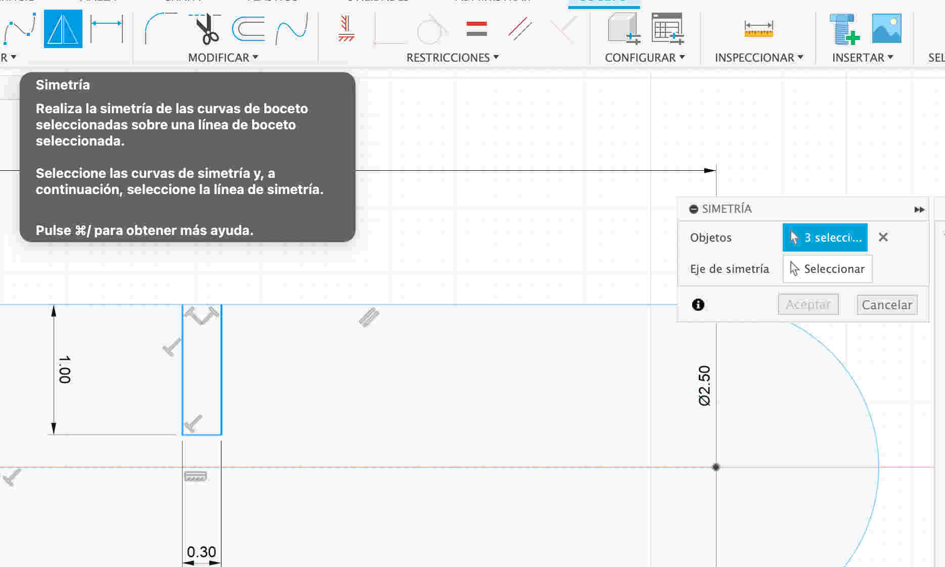
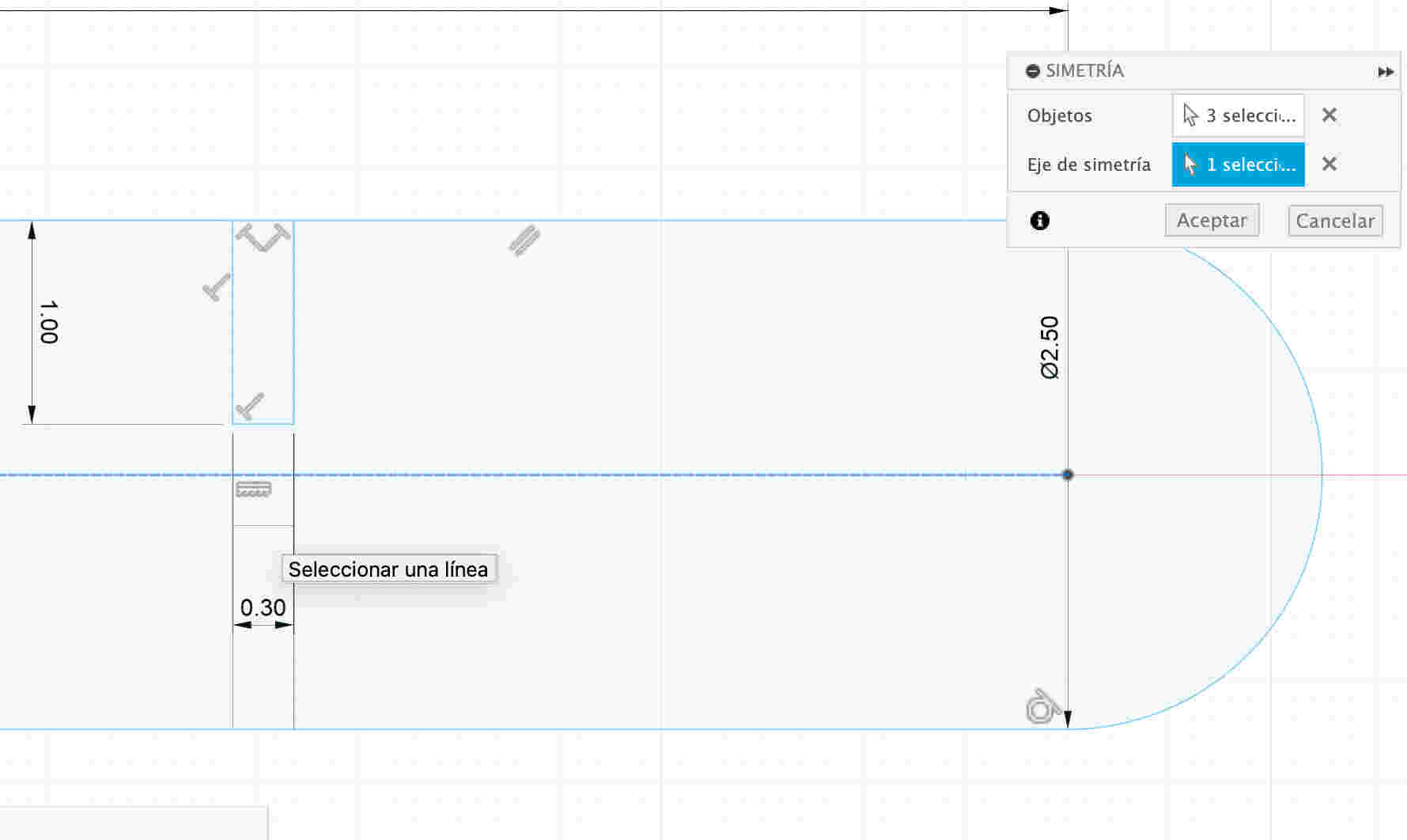
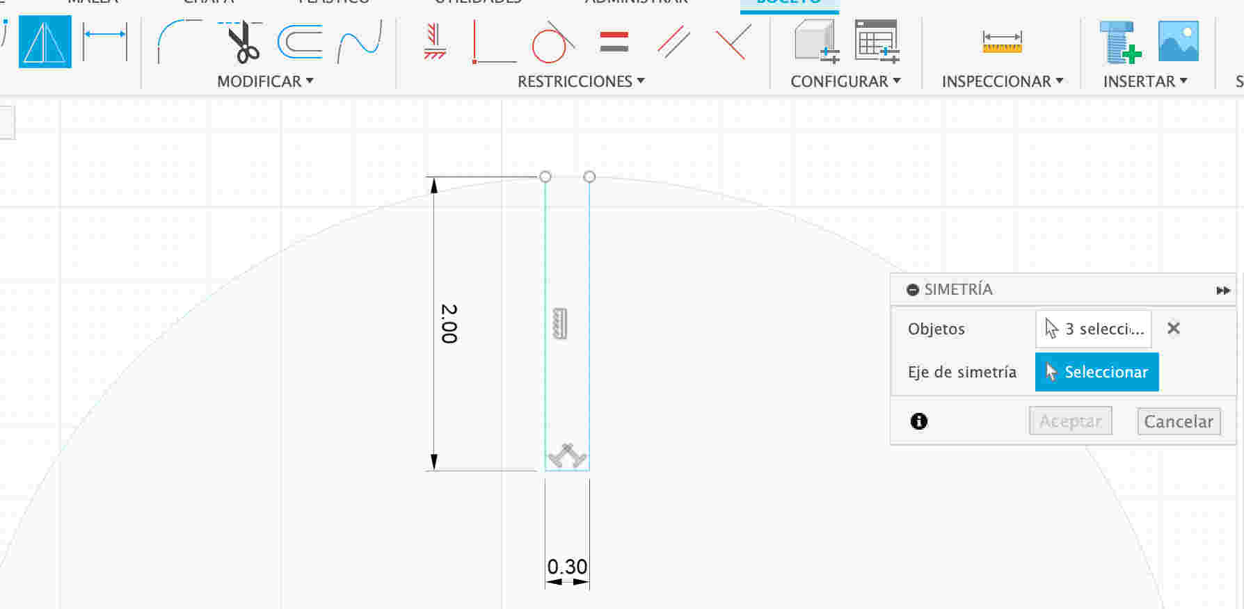
I used the symmetry tool to mirror the shape on the opposite side, ensuring a balanced and uniform design.
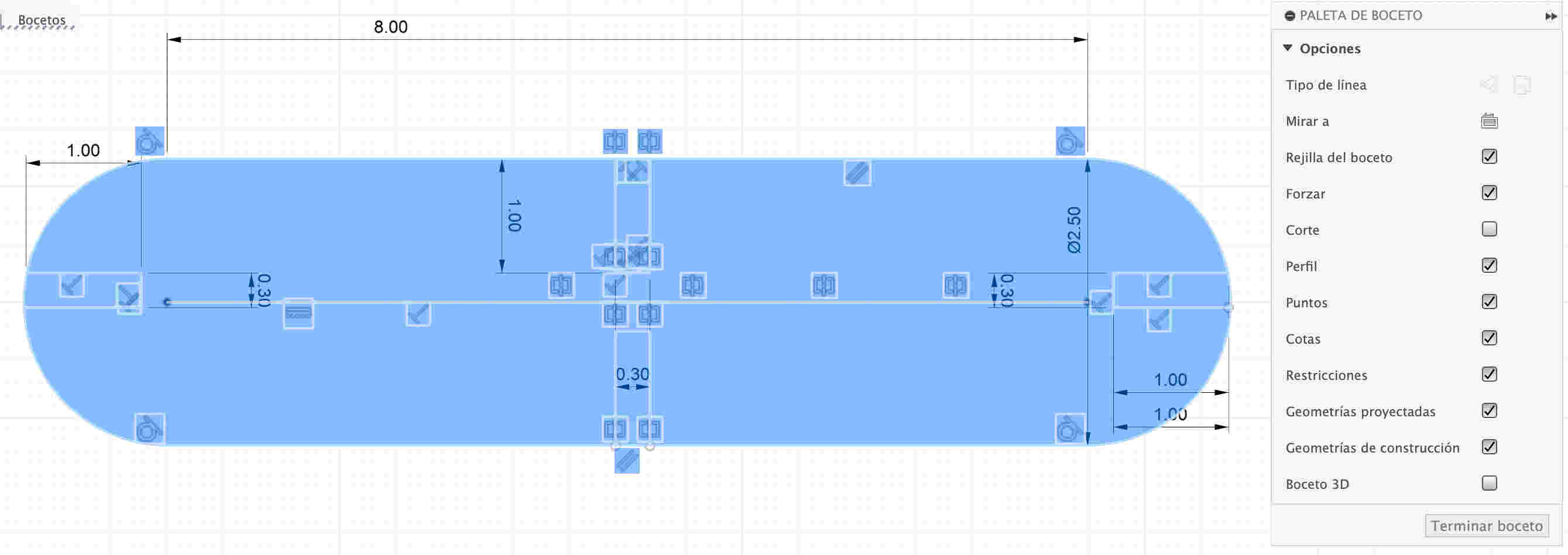
I selected the entire design to more easily identify the nodes and facilitate their manipulation.
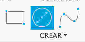
I used the circle tool to create a new piece that will be part of my parametric kit.
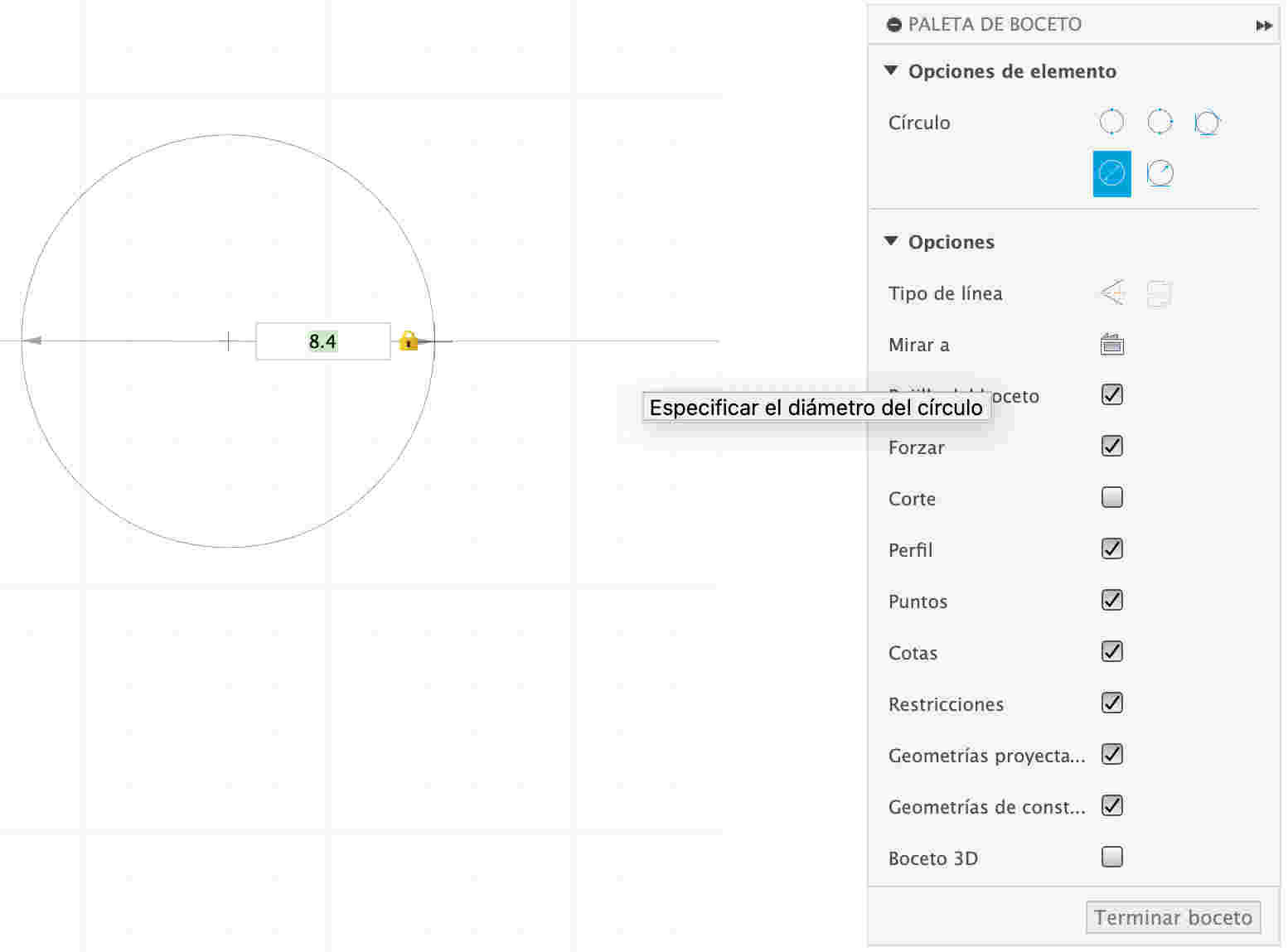
I specified the circle's diameter to ensure precision and compatibility with the other pieces in the kit.
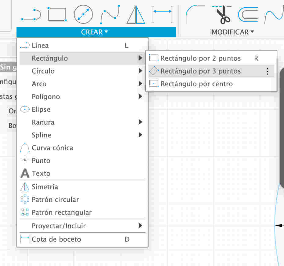
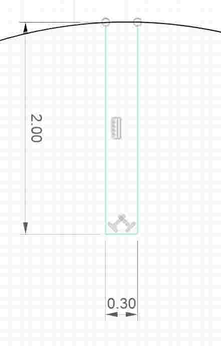
Using the rectangle tool, I created the joint that allows the piece to be pressed and fit with another parametric part.
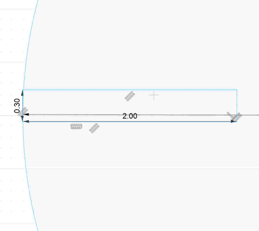
I set a width of 3 mm for the joint to ensure a firm and functional fit with the other pieces.
I drew a line in the center of the design to use it as a reference point when applying symmetry.

I applied symmetry to my rectangle by selecting the center line as a reference, duplicating the shape precisely to the other side.
Same Process
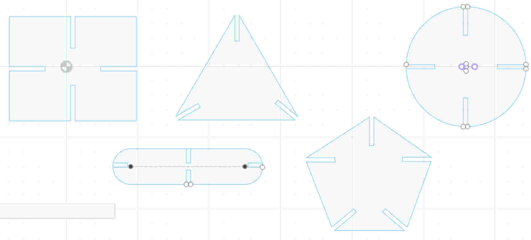
This is the initial prototype of my parametric kit after the first design stage.
Final cut pieces
Cutting and Assembly of My prototype of parametric Kit
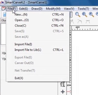
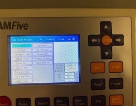
First, I open a new file to start the project.

This is how the main menu appears after opening a new file.
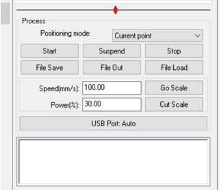
I set the constants with power at 100% and speed at 30%.
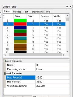
I assigned maximum and minimum power values to the red color, saving them to use 45% max power, 35% min power, and 200% work speed.
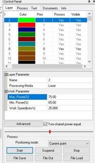
I assigned the desired values to the green color for its maximum and minimum power, saving them for engraving with max power at 75%, min power at 65%, and work speed at 200%.
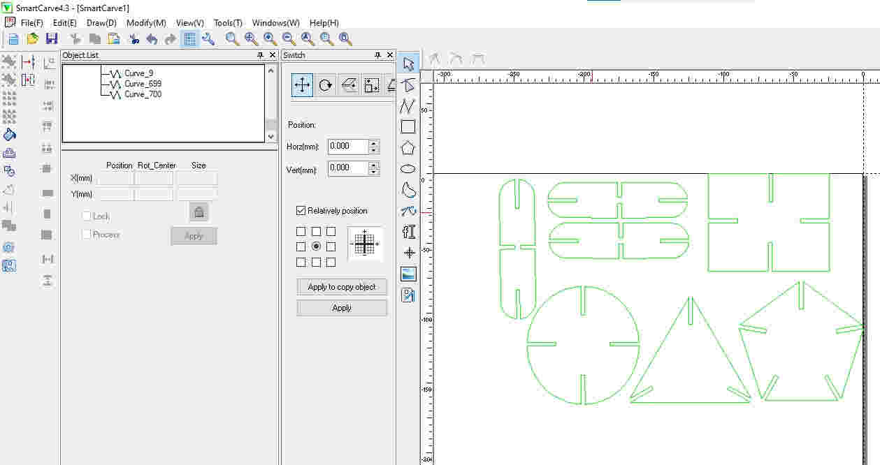
I selected the pieces to cut and applied a color to define their cutting parameters.
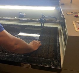
I positioned the material on the laser cutter, aligning it with the reference point to start cutting accurately.
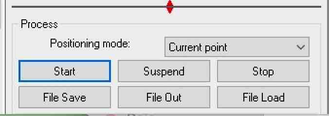
I clicked the "Start" button to begin the cutting process.
I verified the machine to ensure the cutting data was sent correctly.
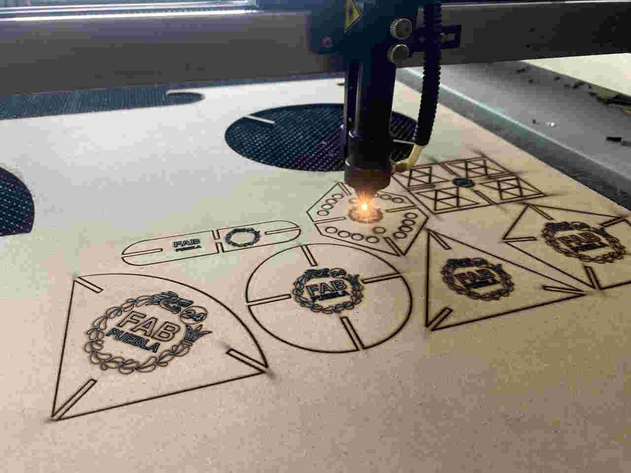
The machine performed the cut accurately and without errors.
With the pieces of my prototype already cut, I will press-fit them together to build a functional structure.
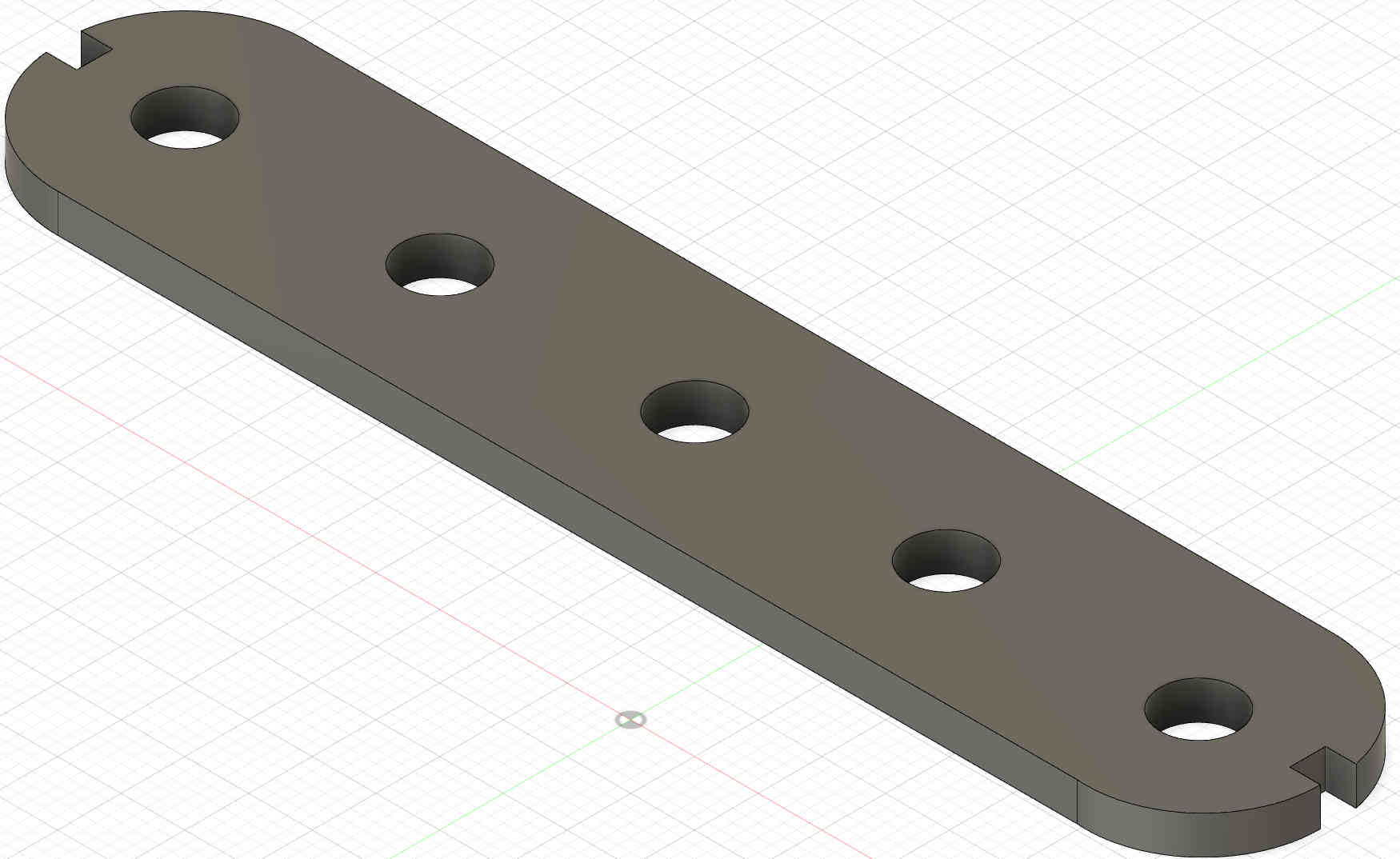
Cutting and Assembly of My Parametric Kit
SI opened Fusion 360 to begin modeling my parametric kit from scratch, setting up the foundation for an adjustable design.
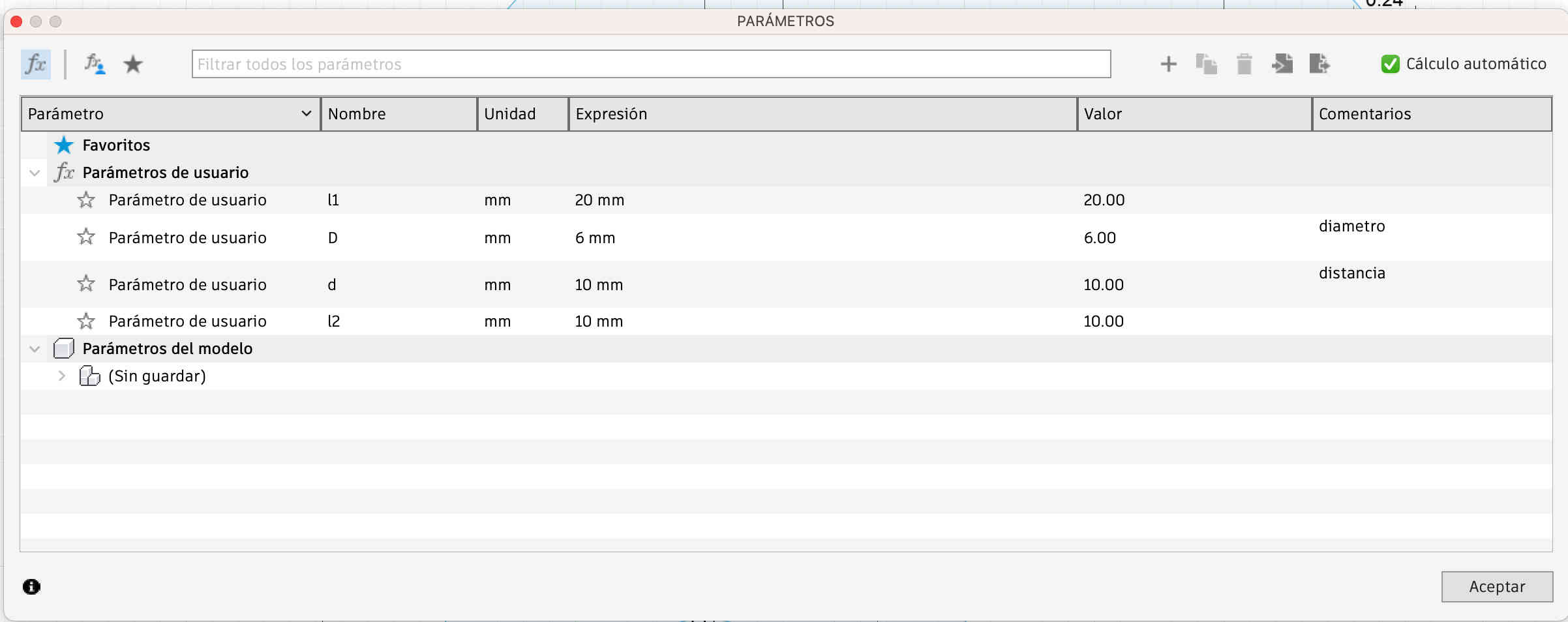
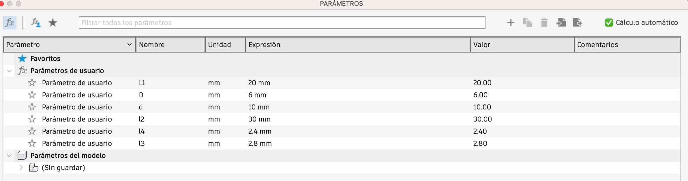
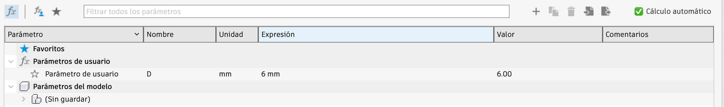
Parameter Definition for Joints
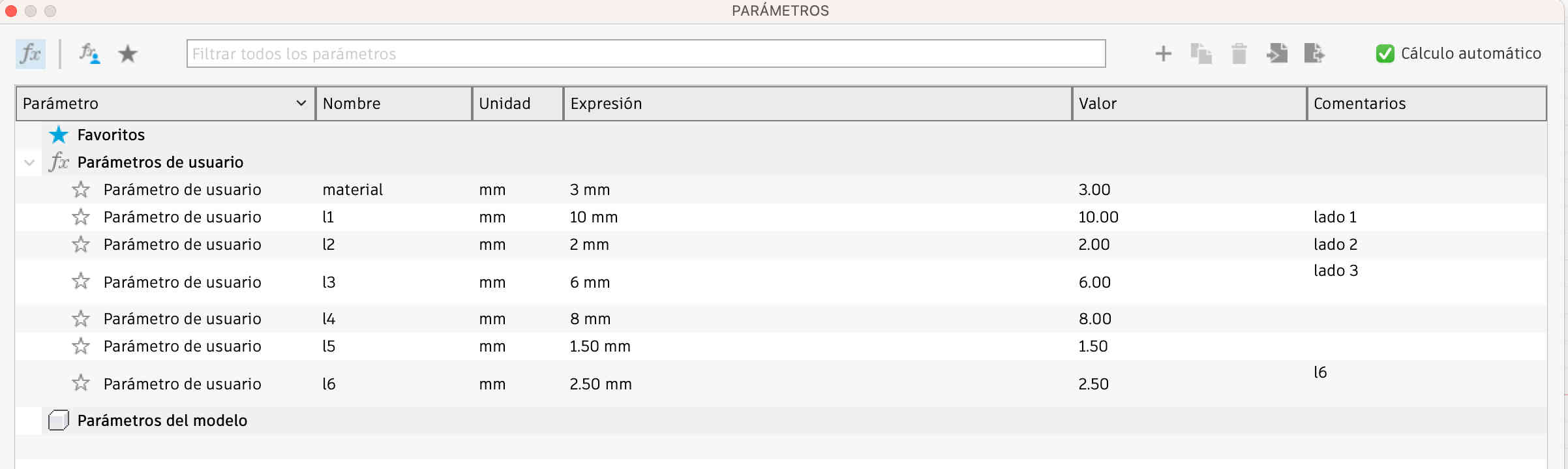
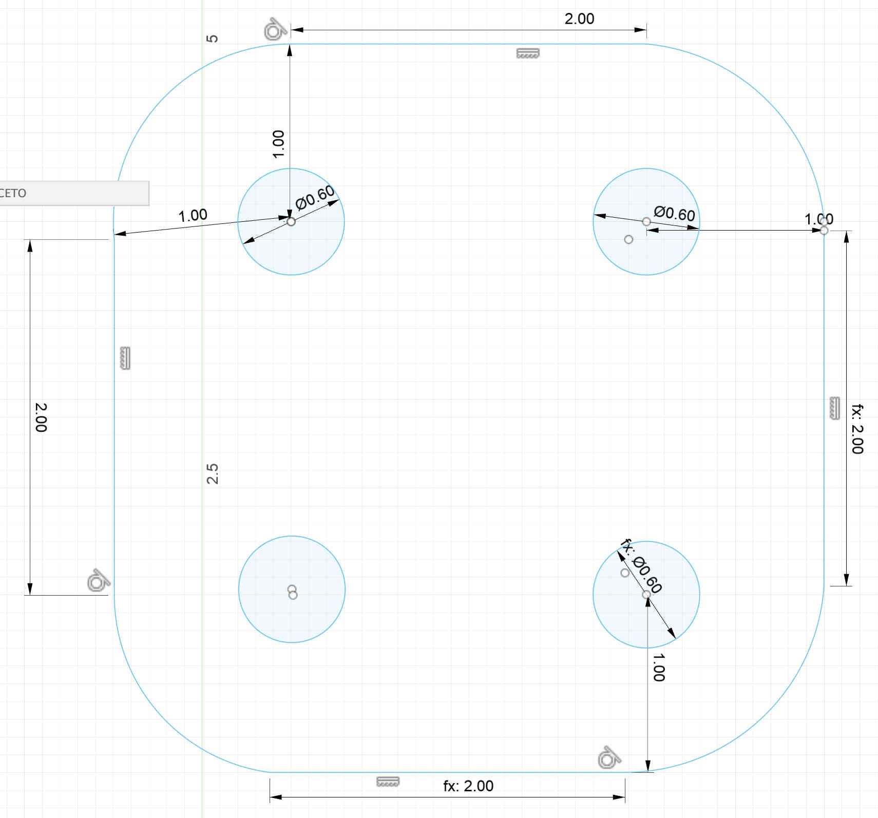
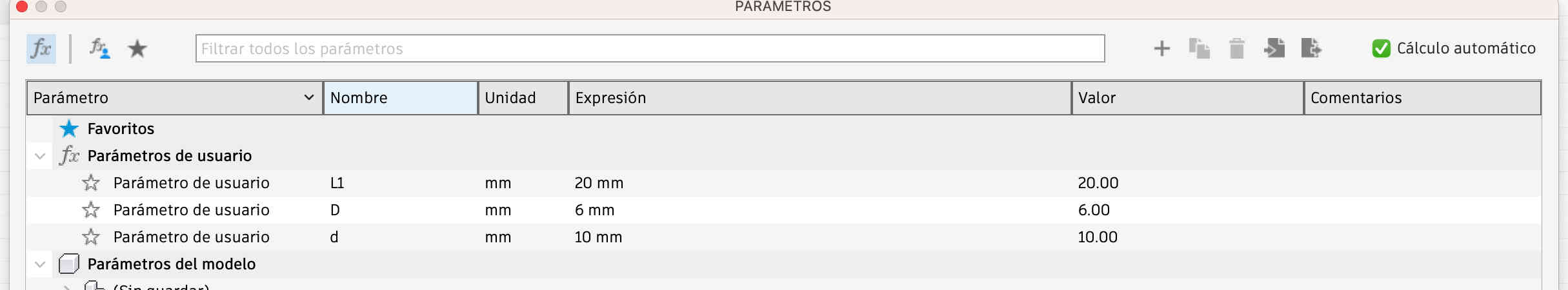
In the parameters tool, I entered specific values to define the dimensions of various geometric shapes, focusing on creating precise and adjustable joints.
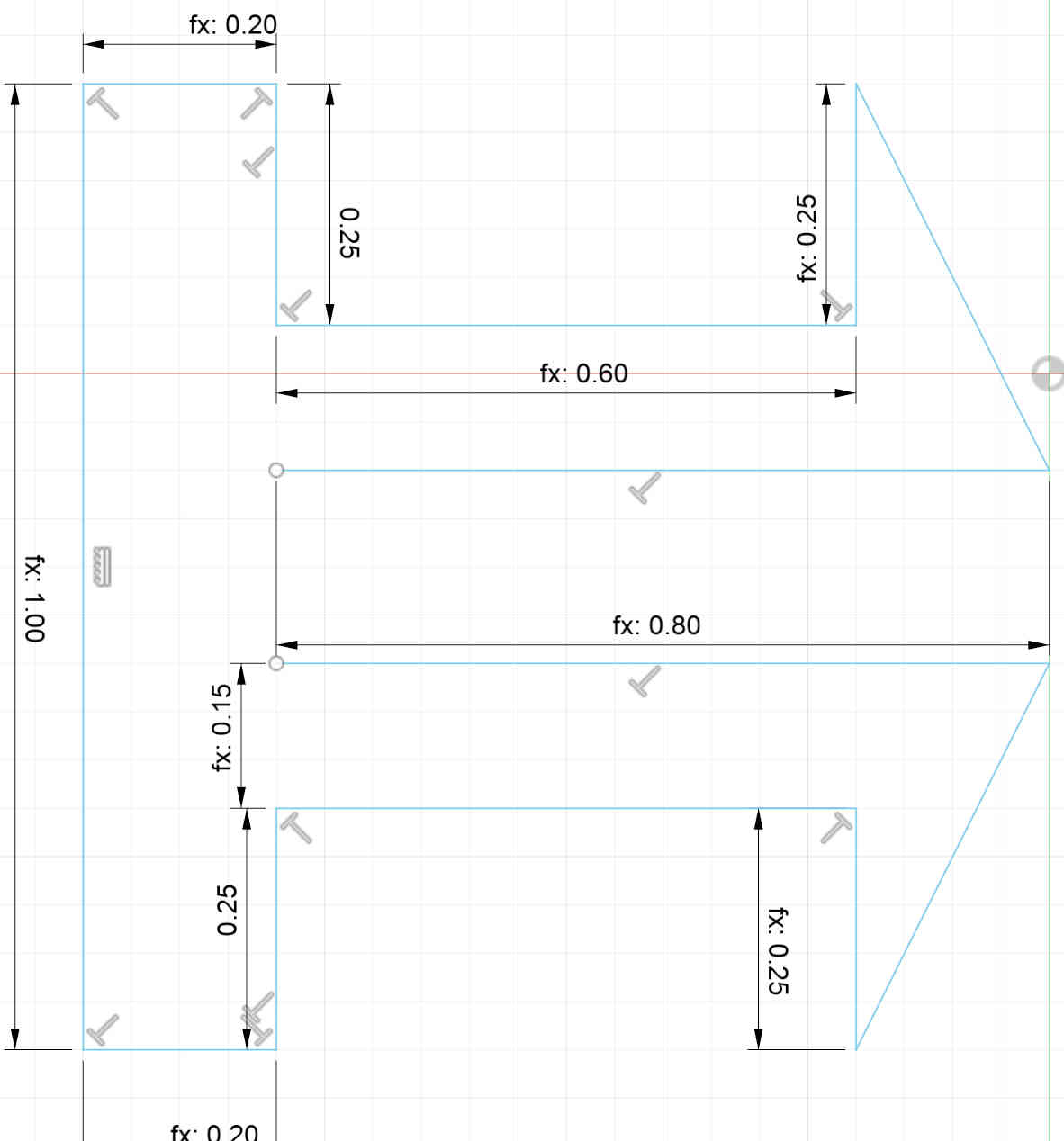
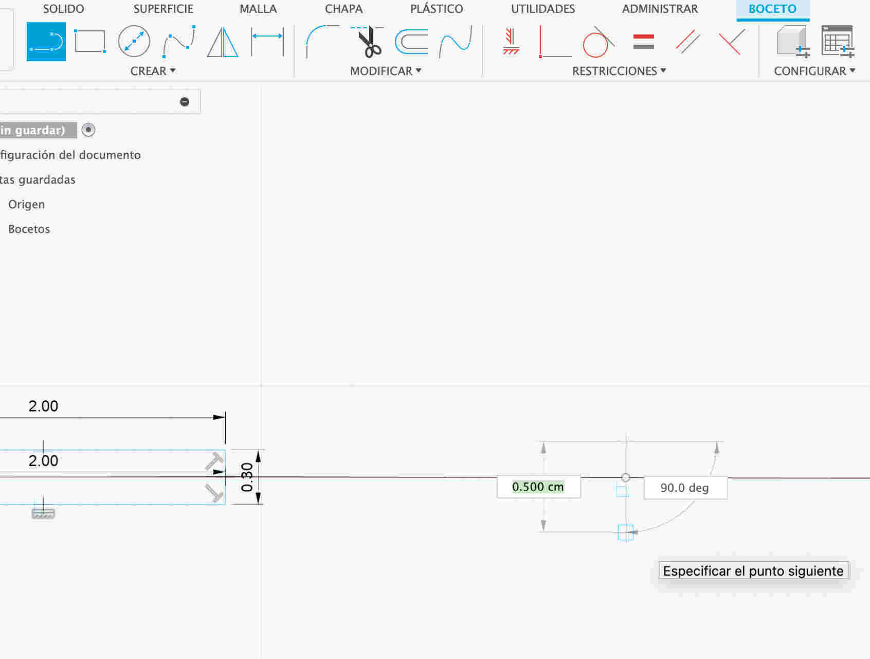
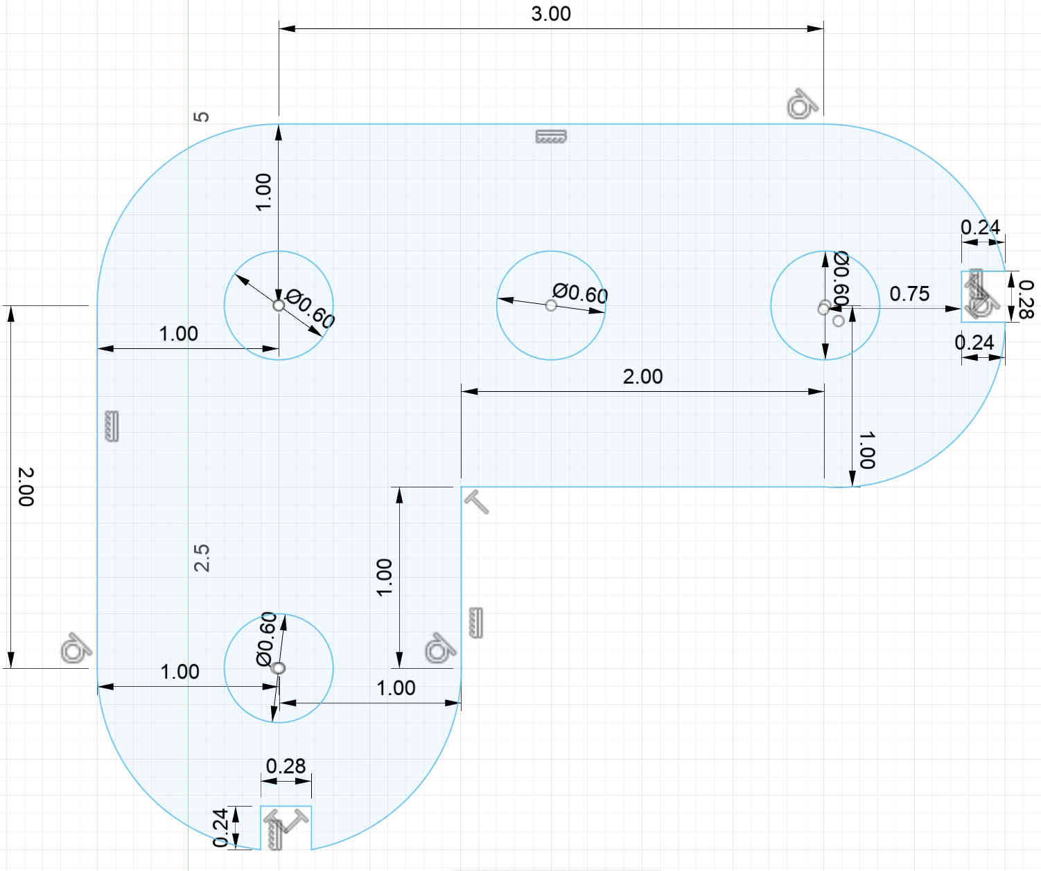
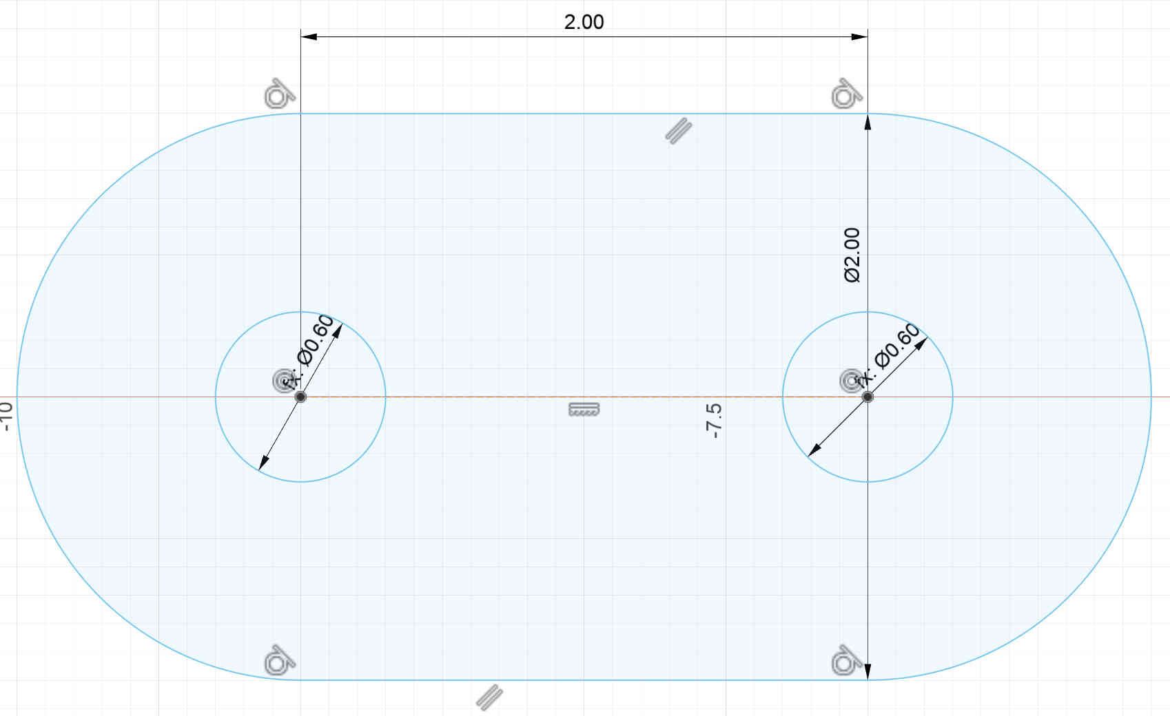
Using the line tool, I clicked on the plane and entered the command with a specific measurement to generate the corresponding parameter.
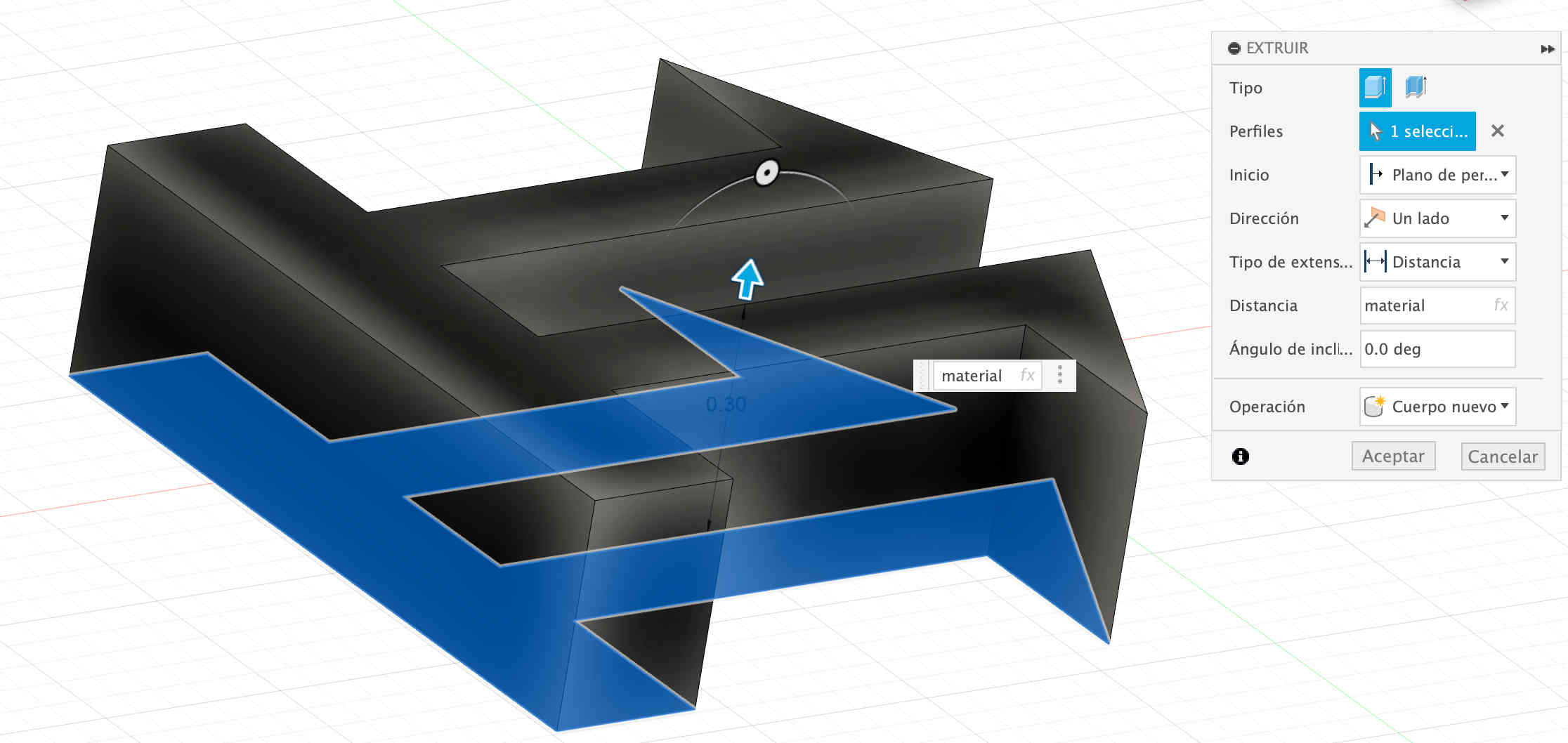
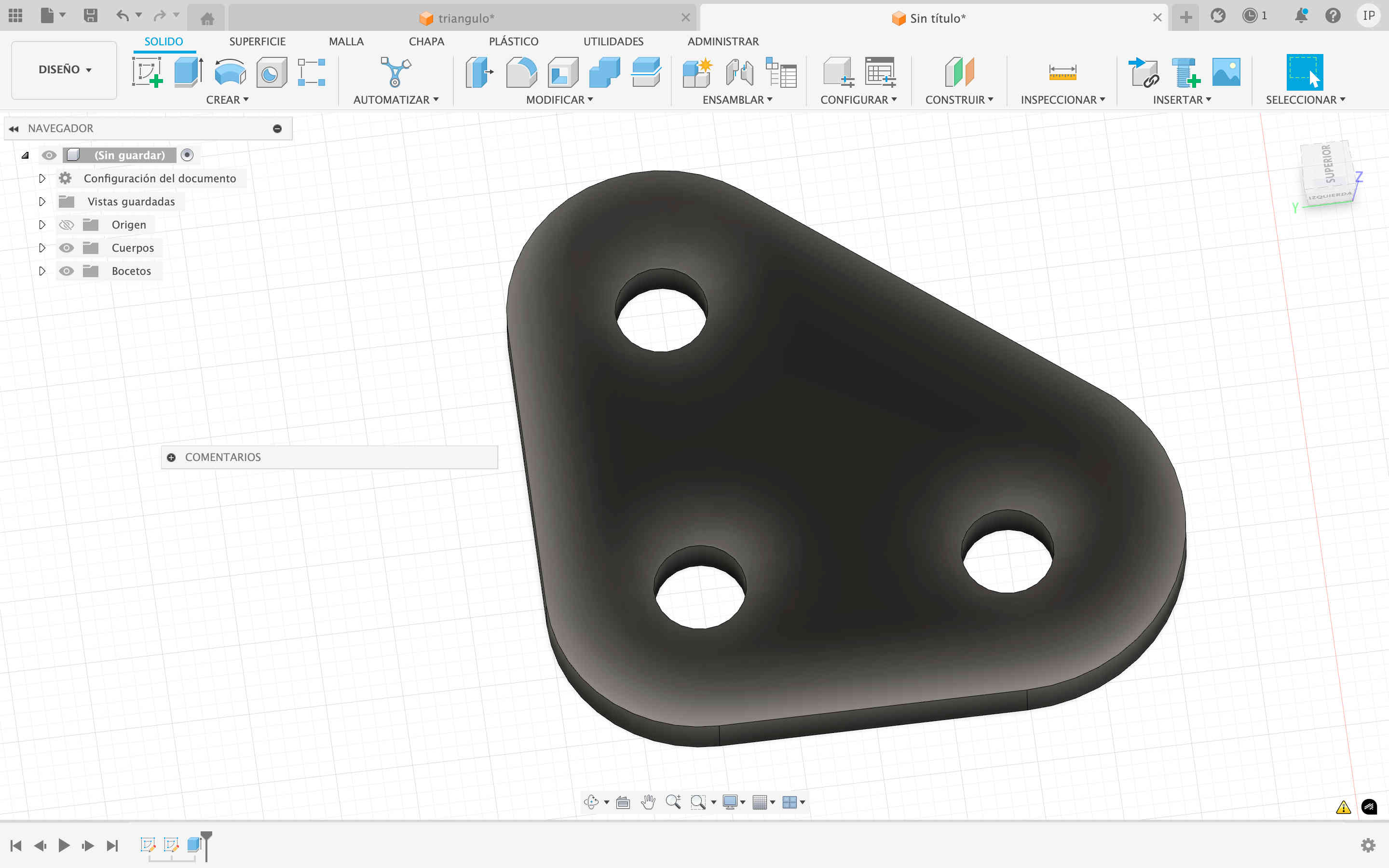
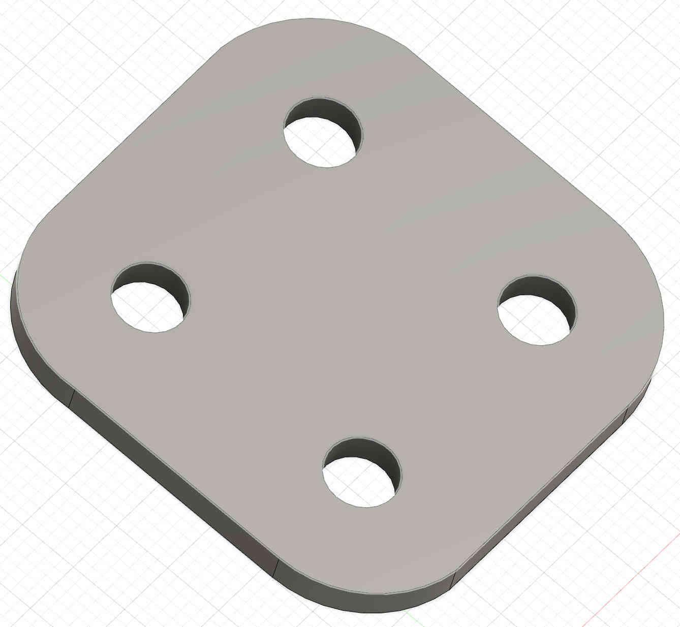
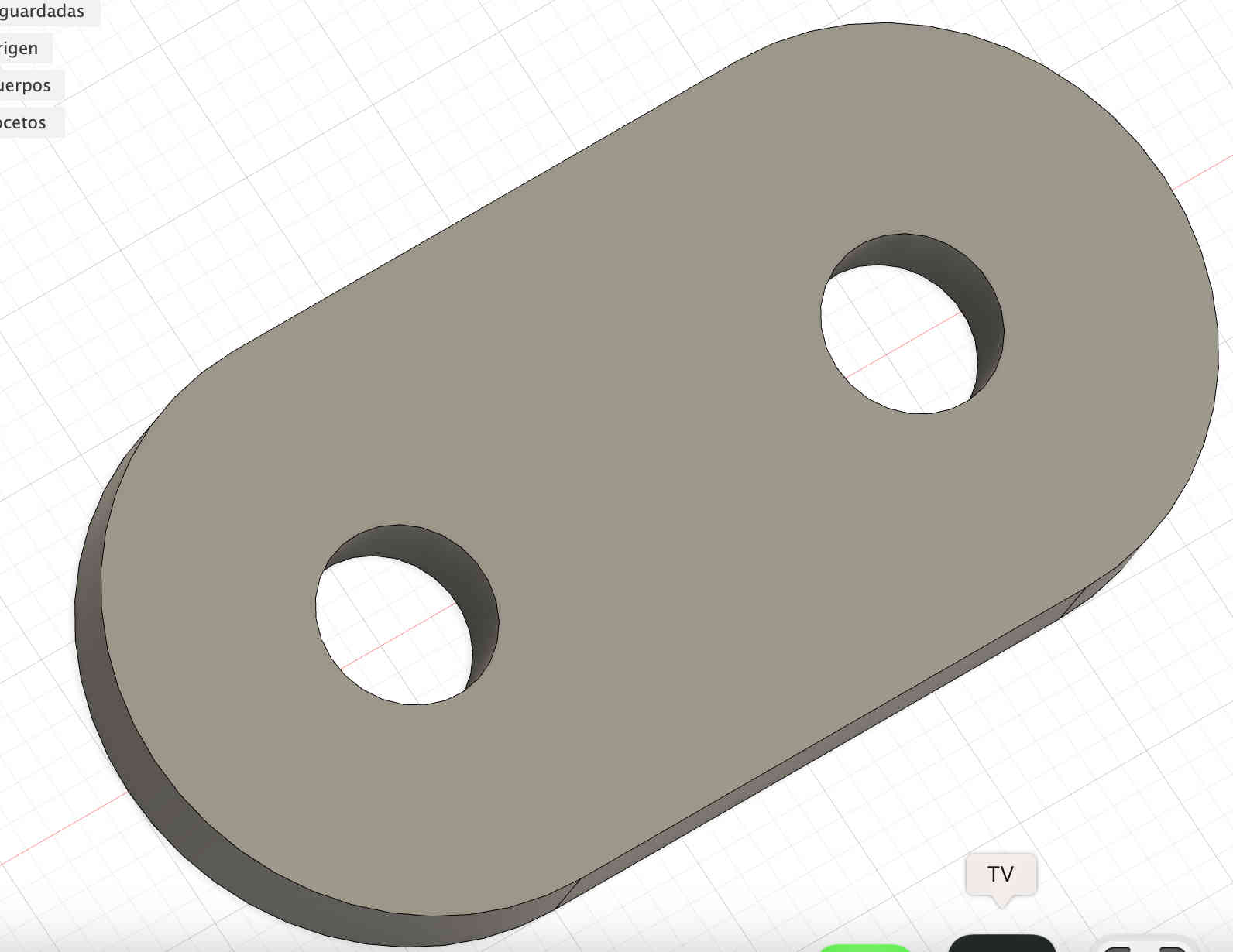
As the final step of this design, I extruded the shape to turn it into a 3D model.
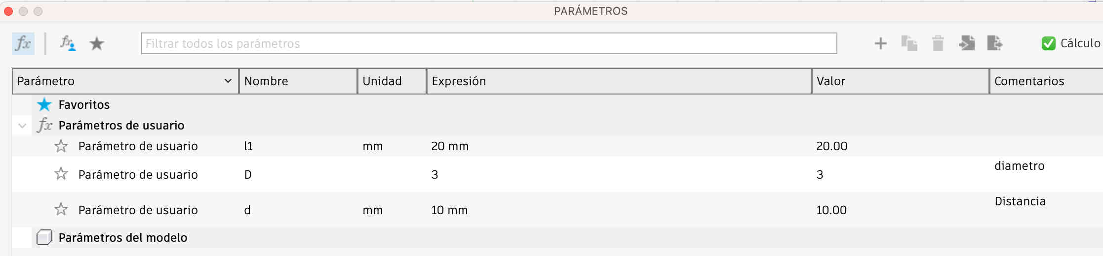
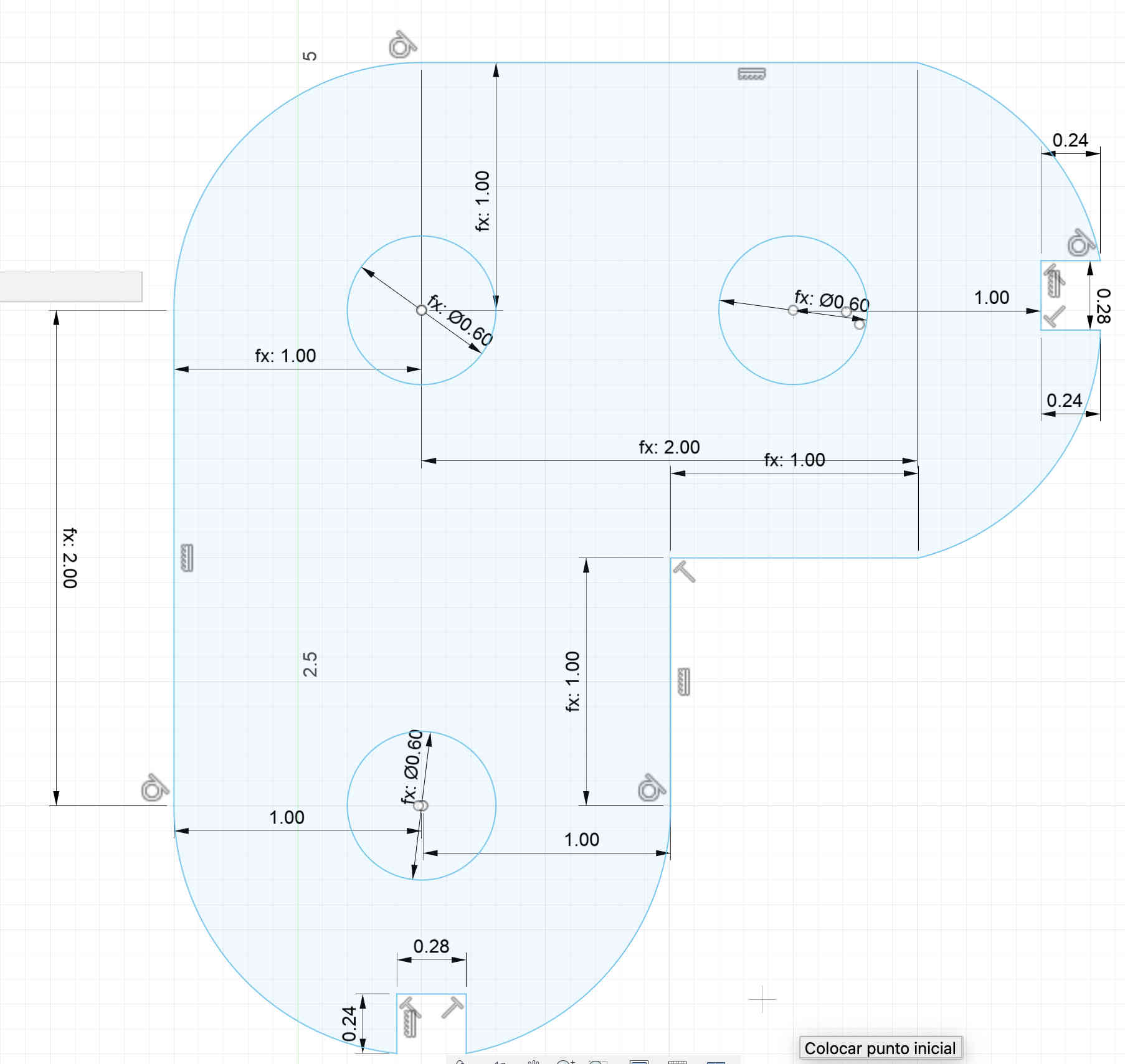
I defined parameters for each of my shapes to save time and enhance efficiency in managing dimensions.
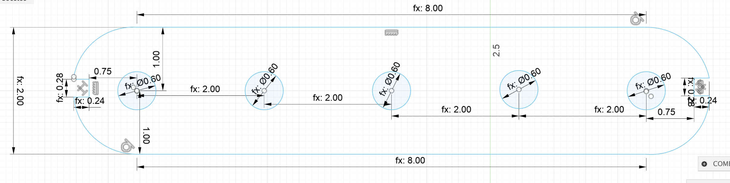
I added my commands to the dimensions to link them directly to the defined parameters.
I extruded my shape to turn it into a three-dimensional model.
I defined parameters for each of my shapes to save time and enhance efficiency in managing dimensions.
I added my commands to the dimensions to link them directly to the defined parameters.
I extruded my shape to turn it into a three-dimensional model.
I added my commands to the dimensions to link them directly to the defined parameters.
I defined parameters for each of my shapes to save time and enhance efficiency in managing dimensions.
I extruded my shape to turn it into a three-dimensional model.
I defined parameters for each of my shapes to save time and enhance efficiency in managing dimensions.
I added my commands to the dimensions to link them directly to the defined parameters.
I extruded my shape to turn it into a three-dimensional model.
I added my commands to the dimensions to link them directly to the defined parameters.
I extruded my shape to turn it into a three-dimensional model.
I defined parameters for each of my shapes to save time and enhance efficiency in managing dimensions.
I added my commands to the dimensions to link them directly to the defined parameters.
I extruded my shape to turn it into a three-dimensional model.
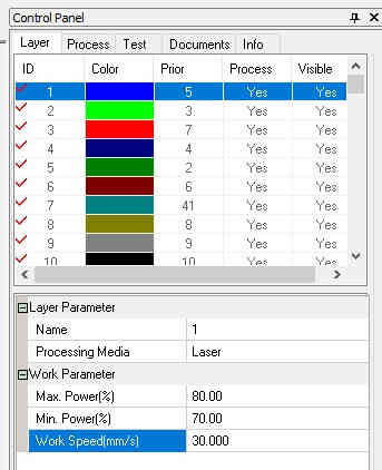
I assigned values to the blue color for cutting, setting max power to 80%, min power to 70%, and work speed to 30%.
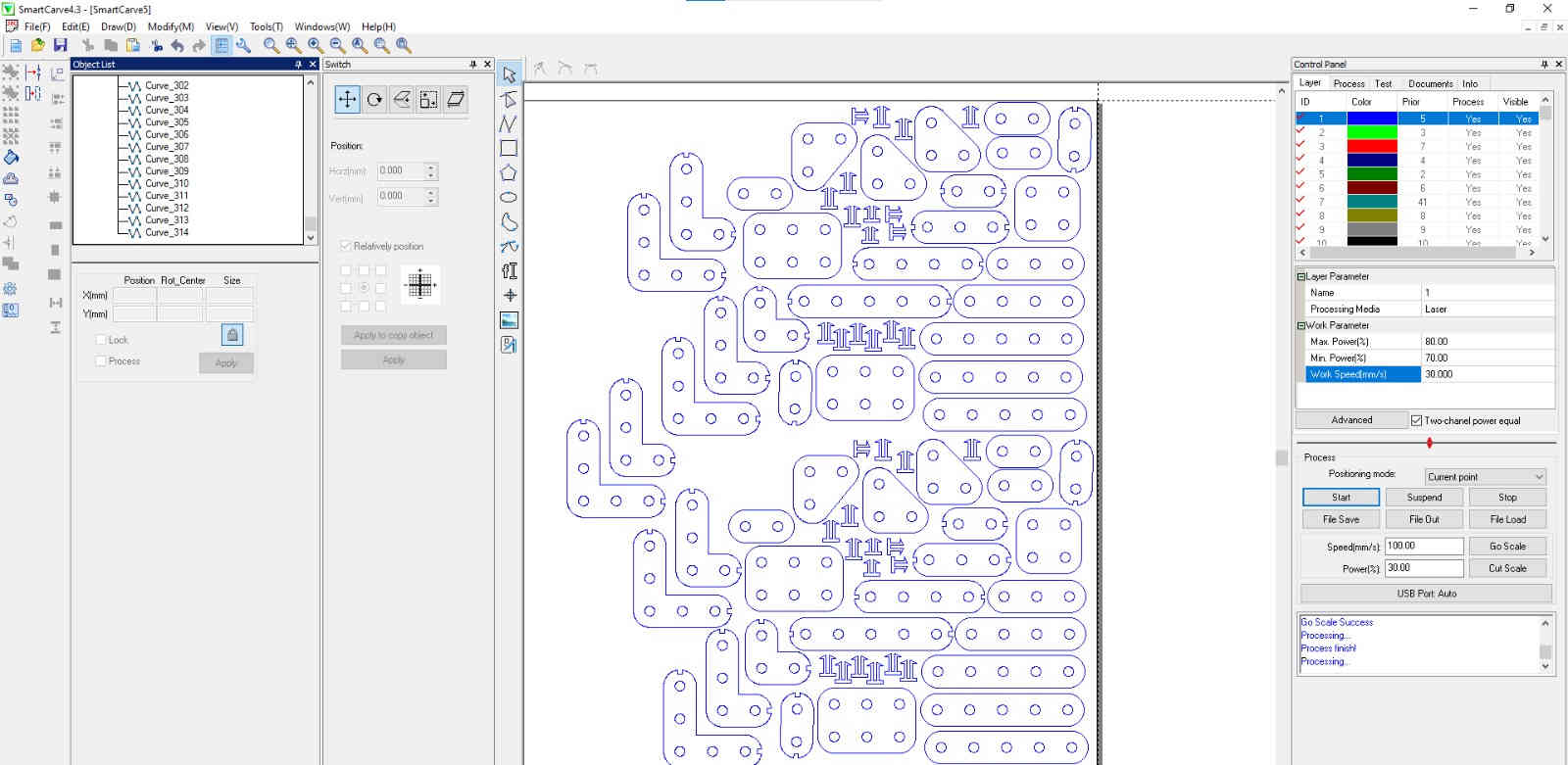
I selected all my shapes and applied the blue color so they would adopt the previously configured cutting values.
I clicked the "Start" button to begin the cutting process.
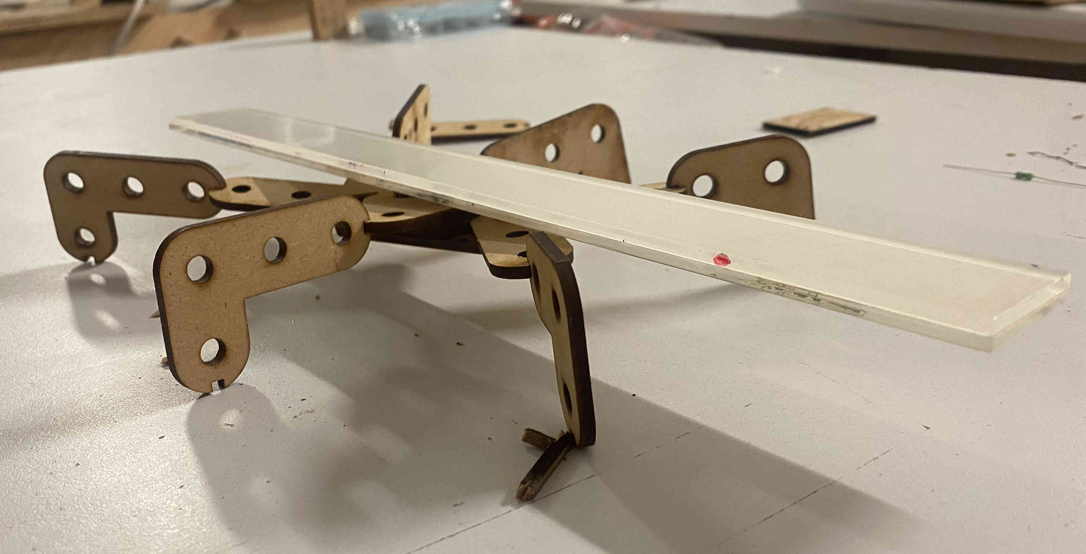
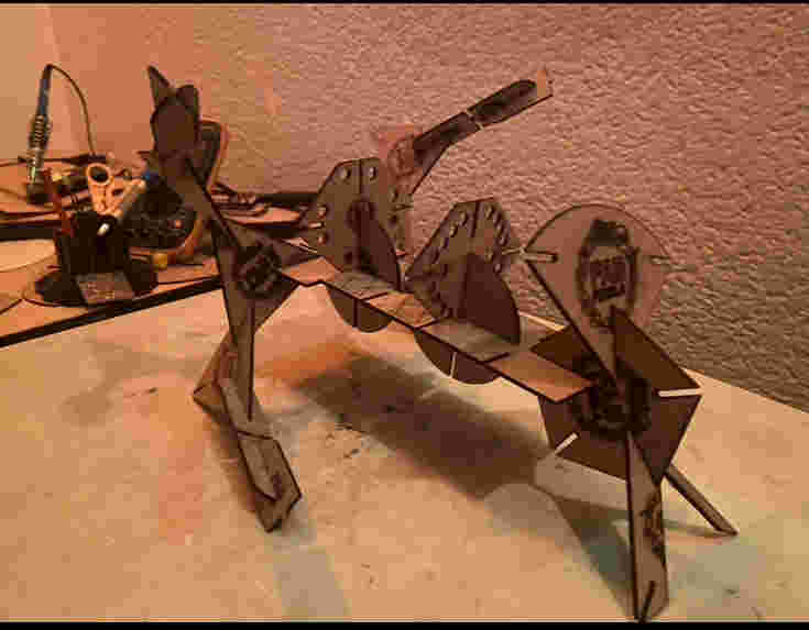
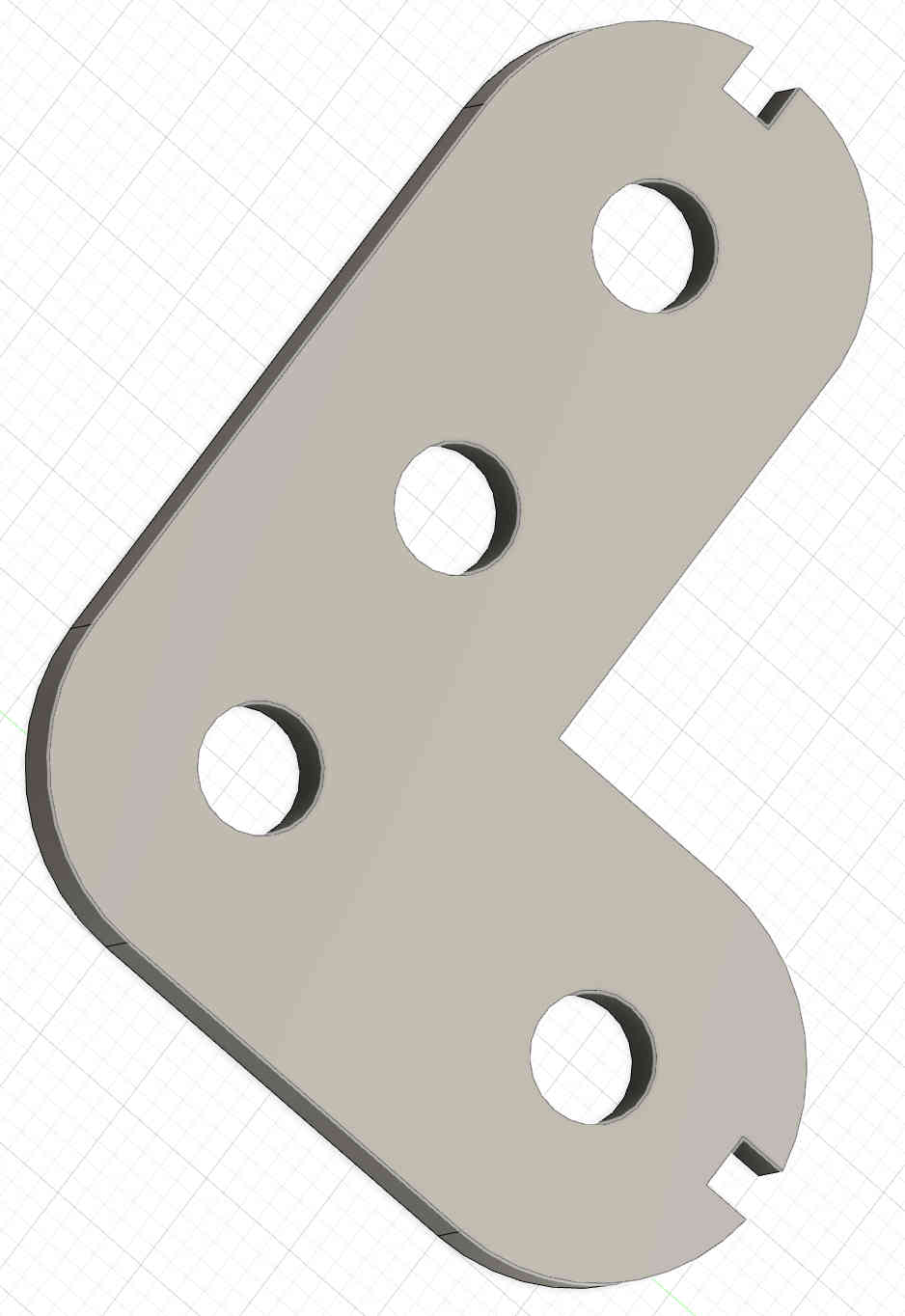
With my shapes already cut, I assembled a spider-like structure, demonstrating the functionality of the parametric design.
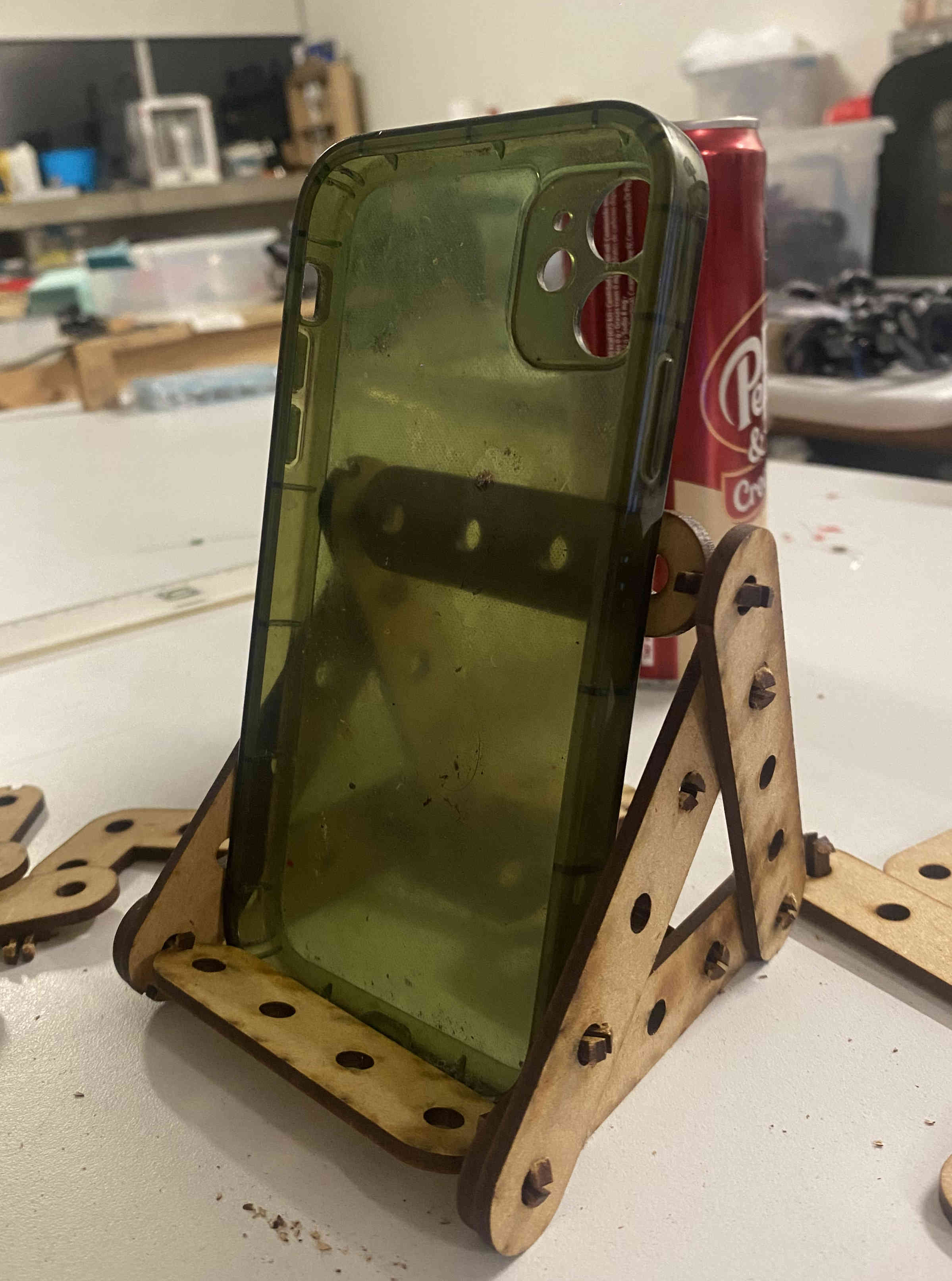
With my shapes already cut, I assembled a 90-degree phone stand.
My press kit
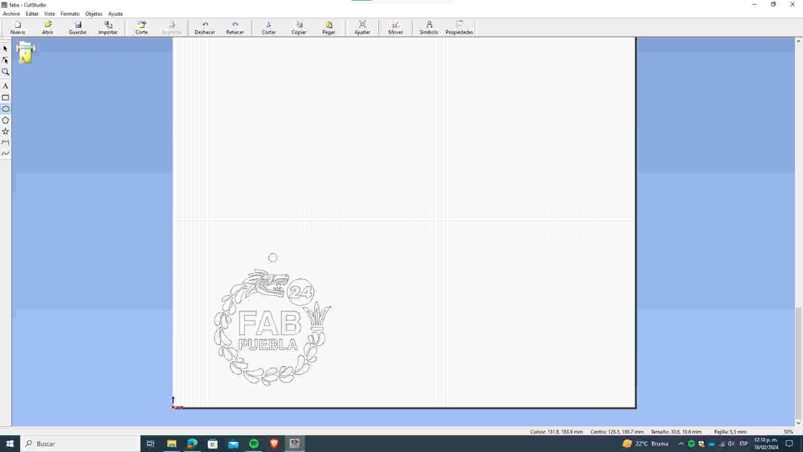
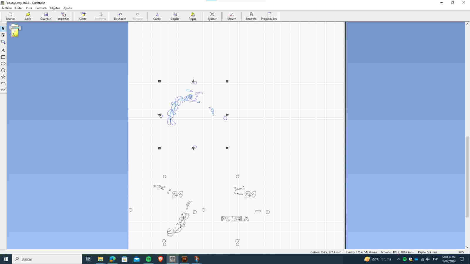
I opened Cut Studio as the interface to carry out the vinyl cutting process.
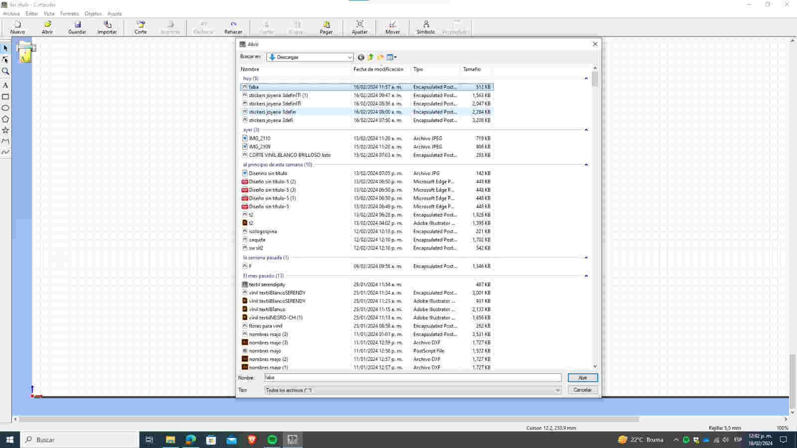
I imported the document in EPS format to prepare it in Cut Studio.
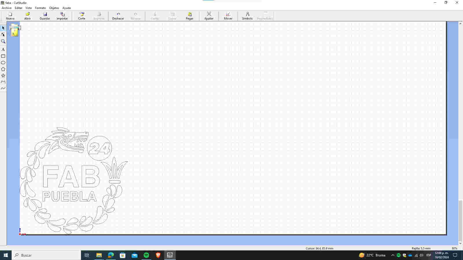
This is how my imported file appears in Cut Studio.
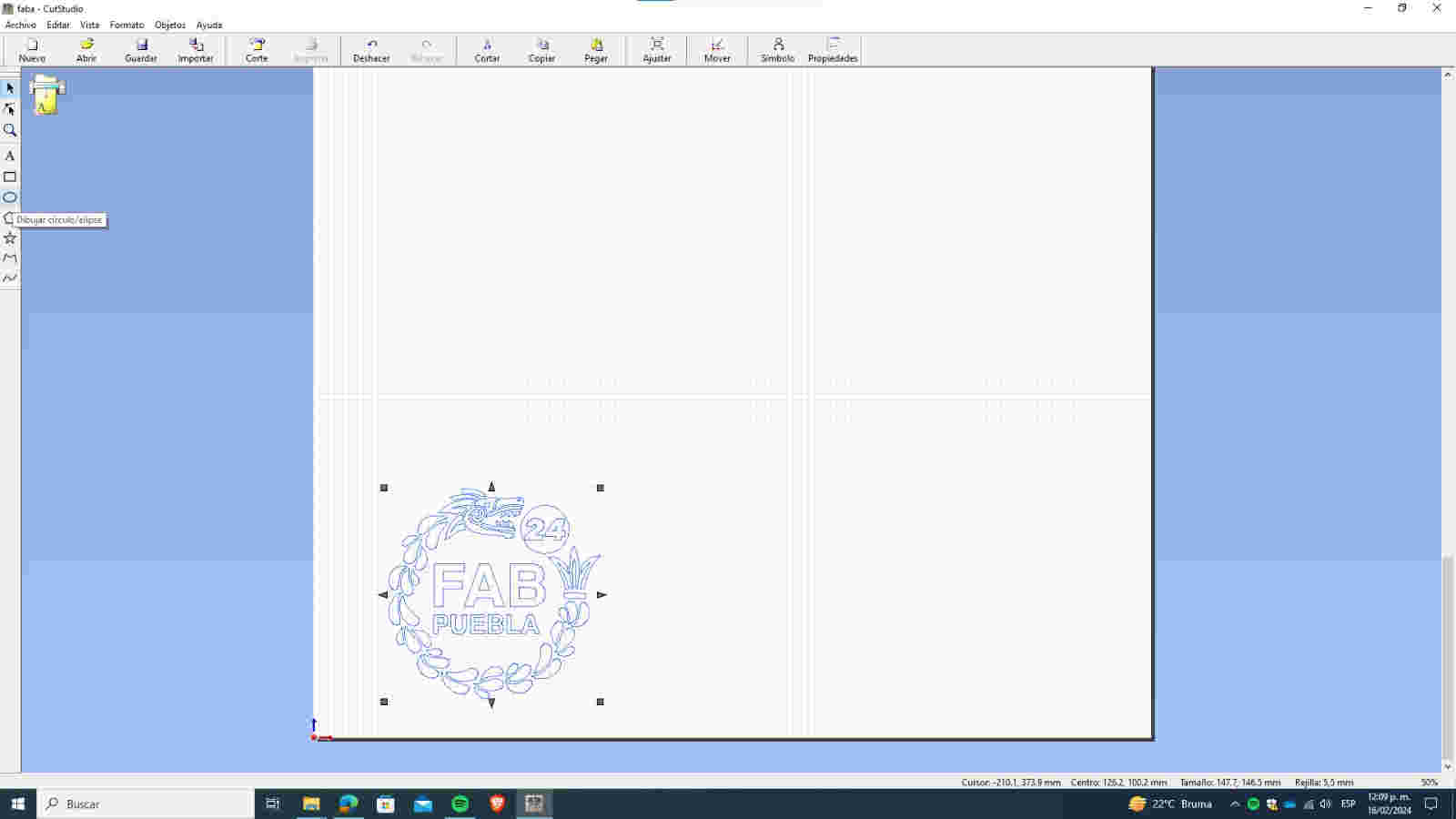
I clicked on the circle tool to create one.
I added circles on the four sides, without touching the design
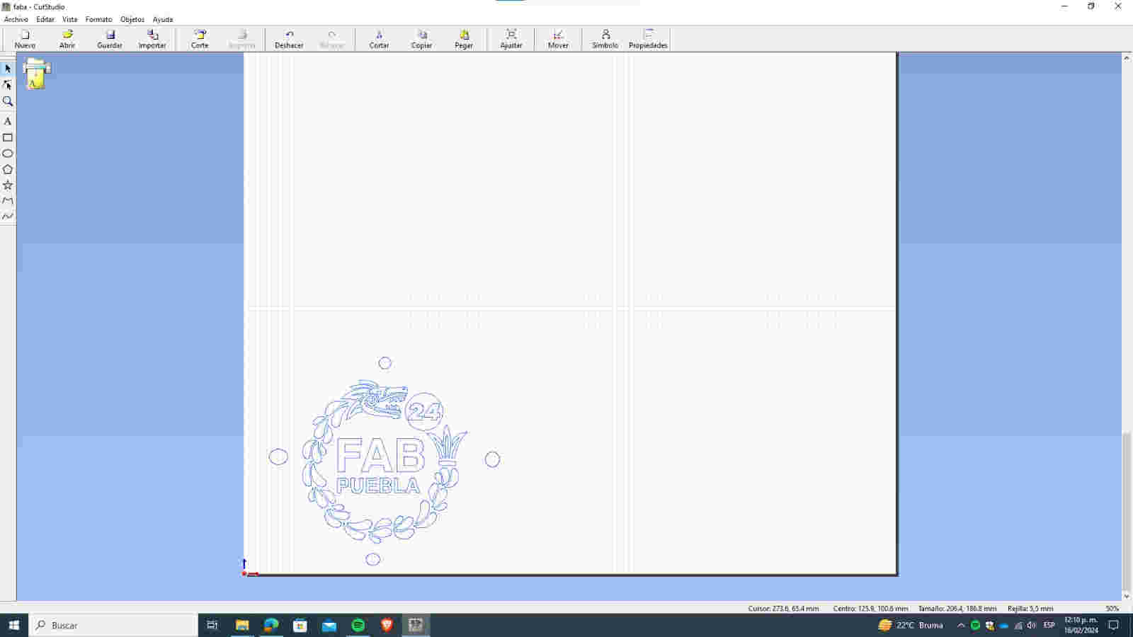
The circles serve as reference marks when applying the vinyl.
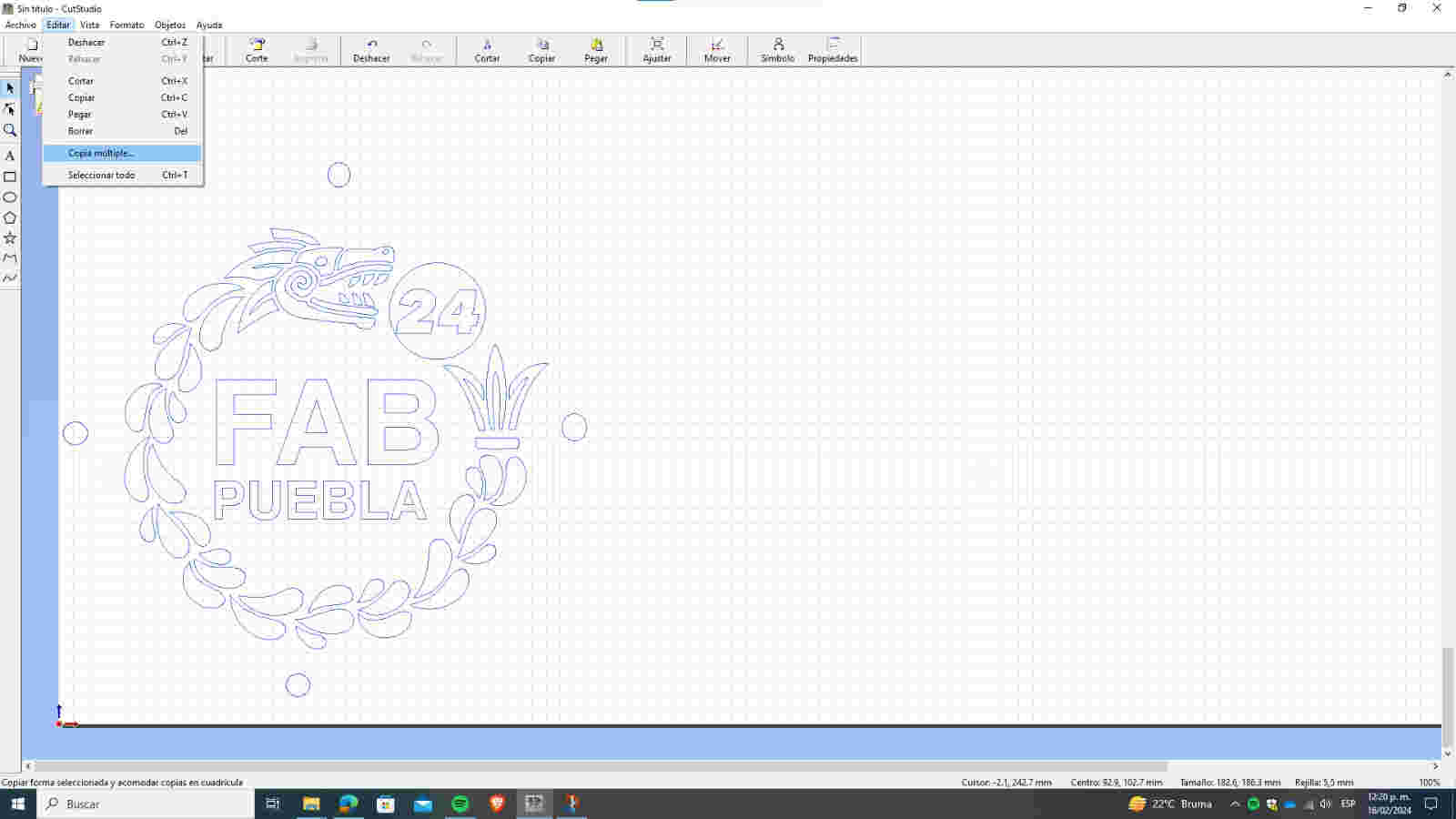
I clicked on "Edit" and then on "Multiple Copy" from the menu to quickly and easily generate several copies.
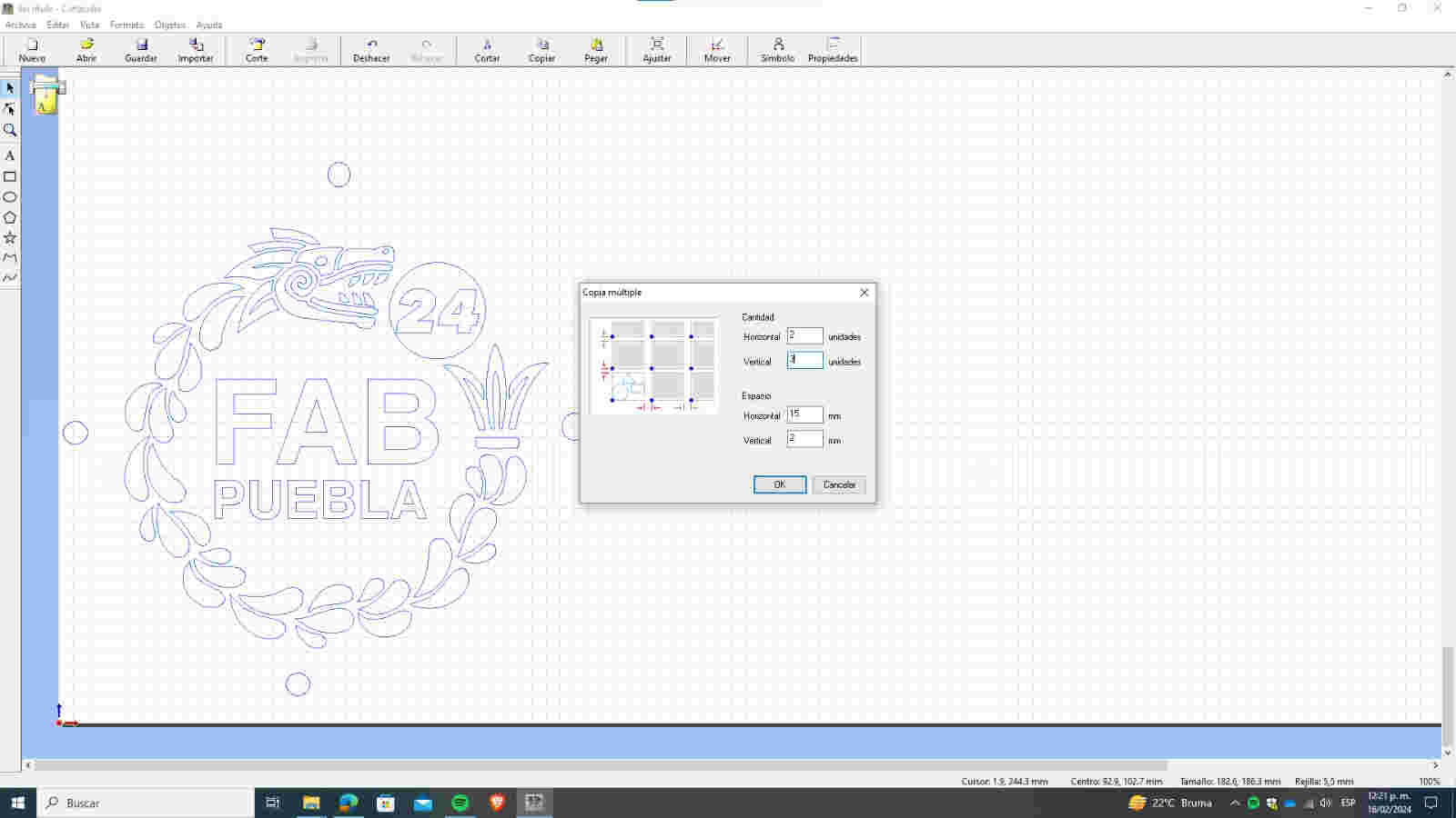
In the options, I specified how many copies I wanted vertically and horizontally, as well as the spacing between them.

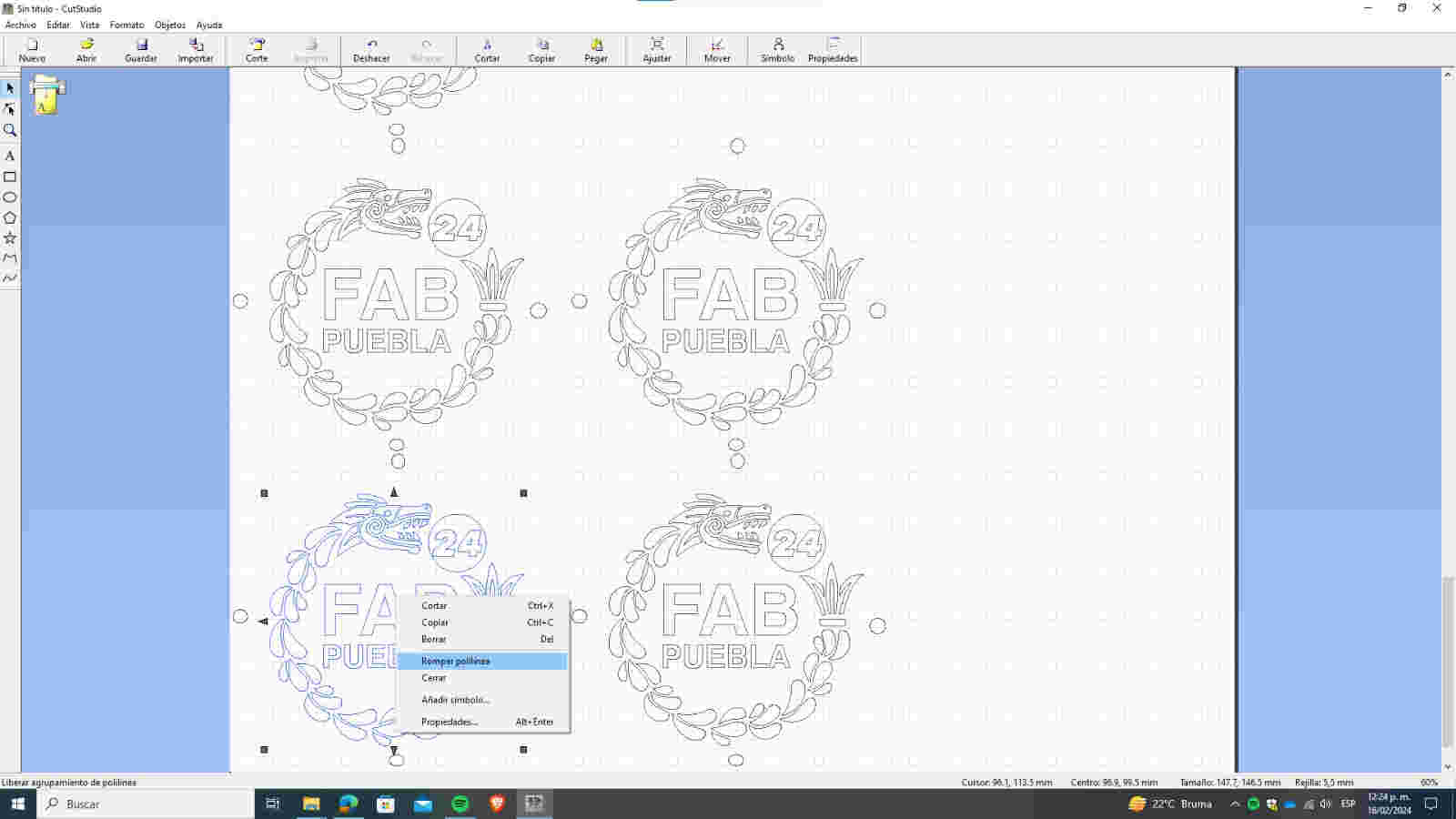
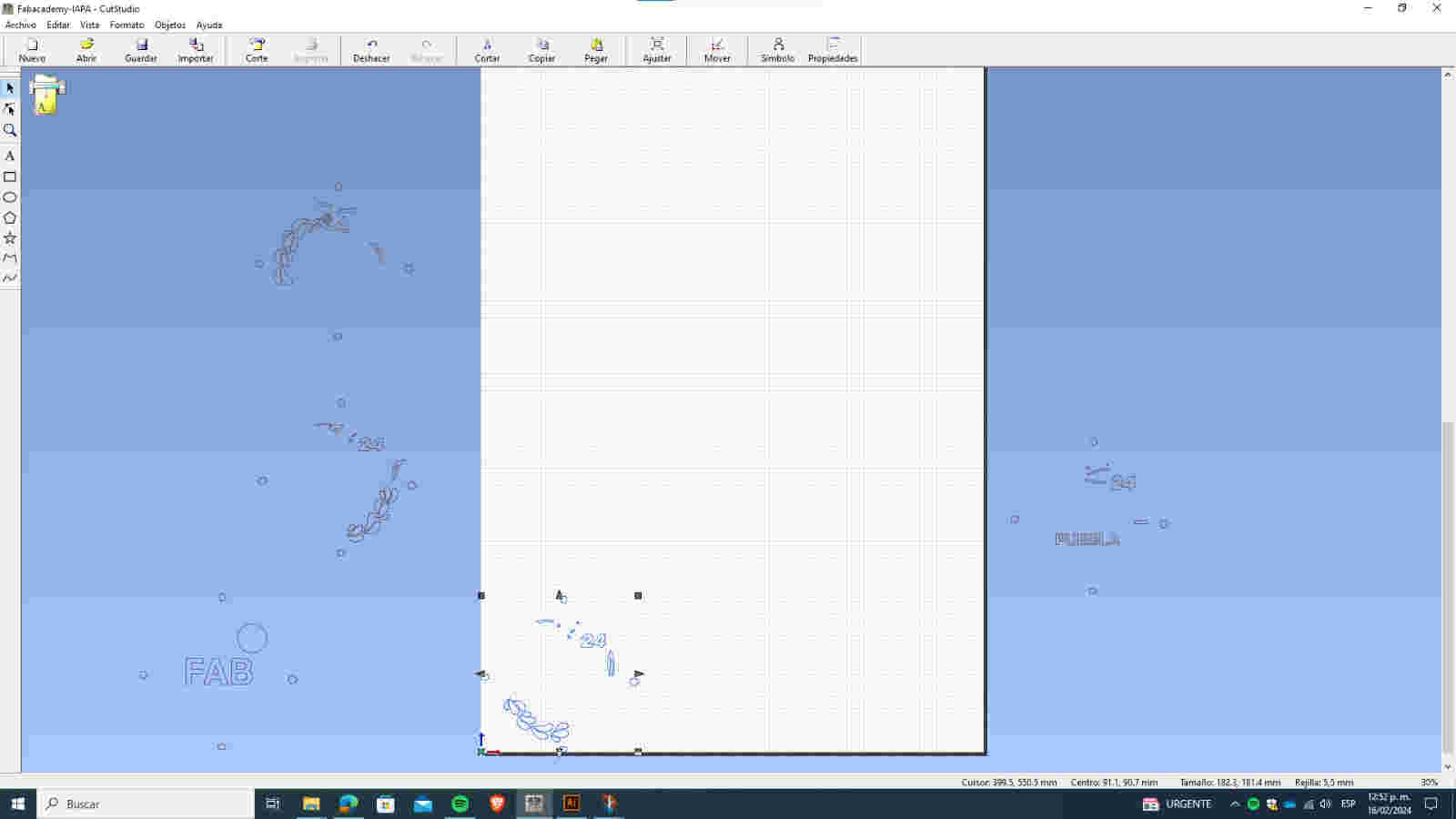
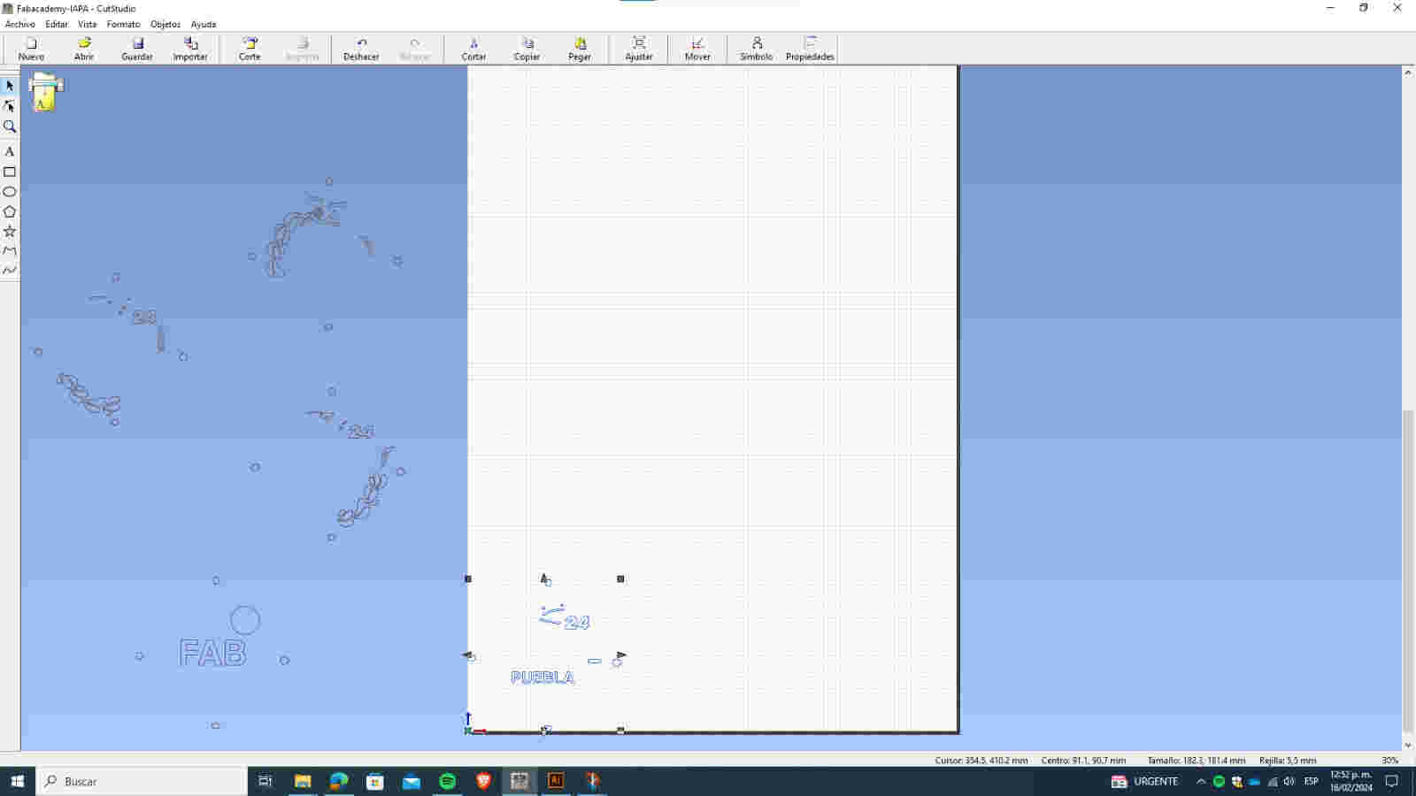
I broke the polyline to organize the cutting order based on the color phases I want.
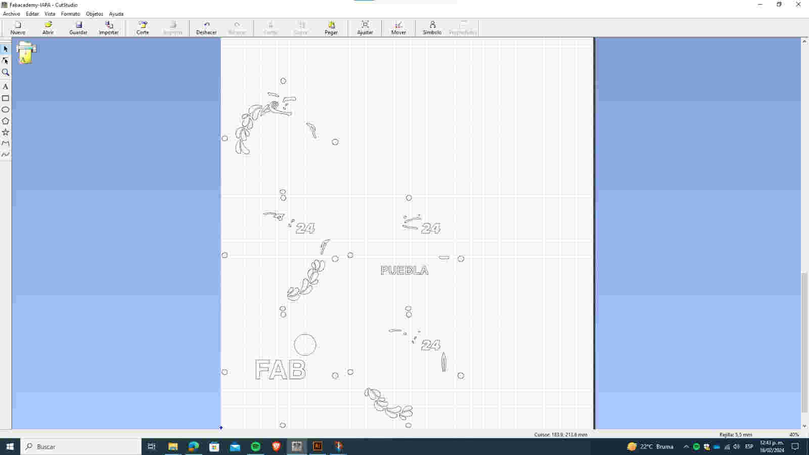
I arrange each section of my design by colors, setting the order in which I want them to be cut.
I selected a section of the design to edit it.
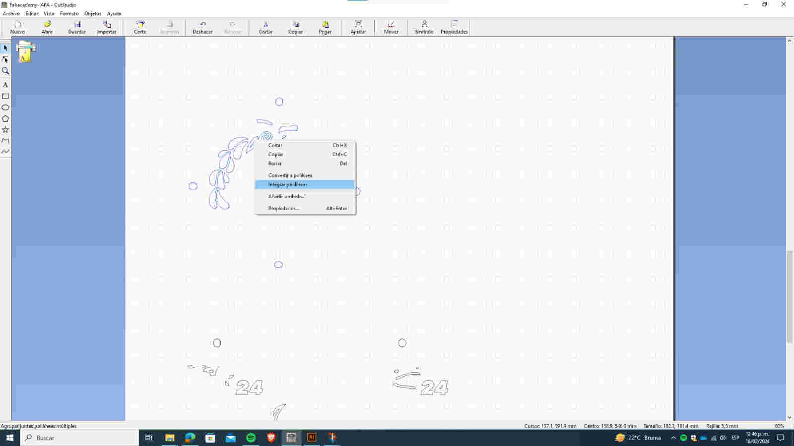
I joined my entire design into a single polyline to create a unified shape.
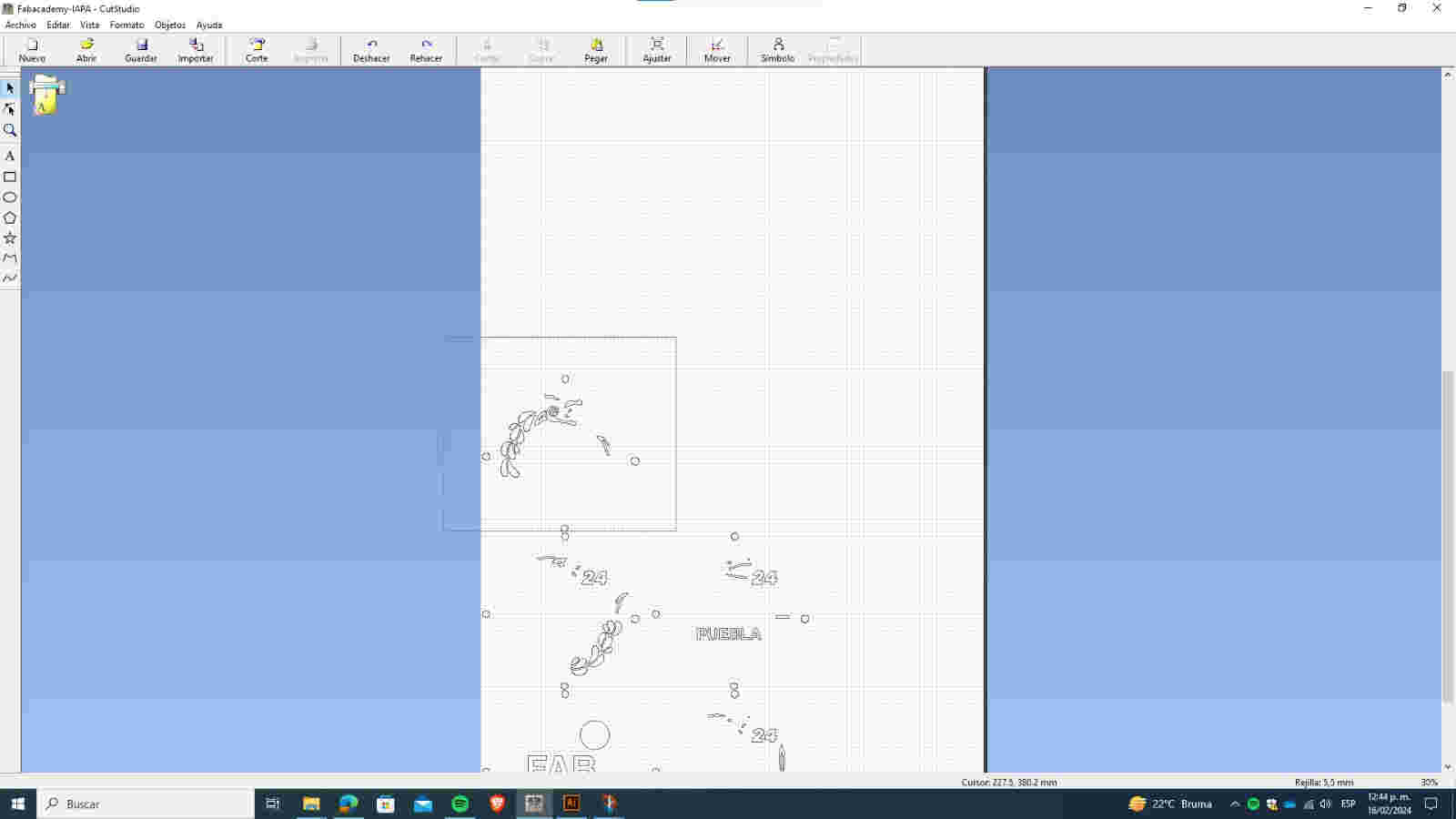
I selected the polyline and dragged it outside the work area to prepare for cutting.
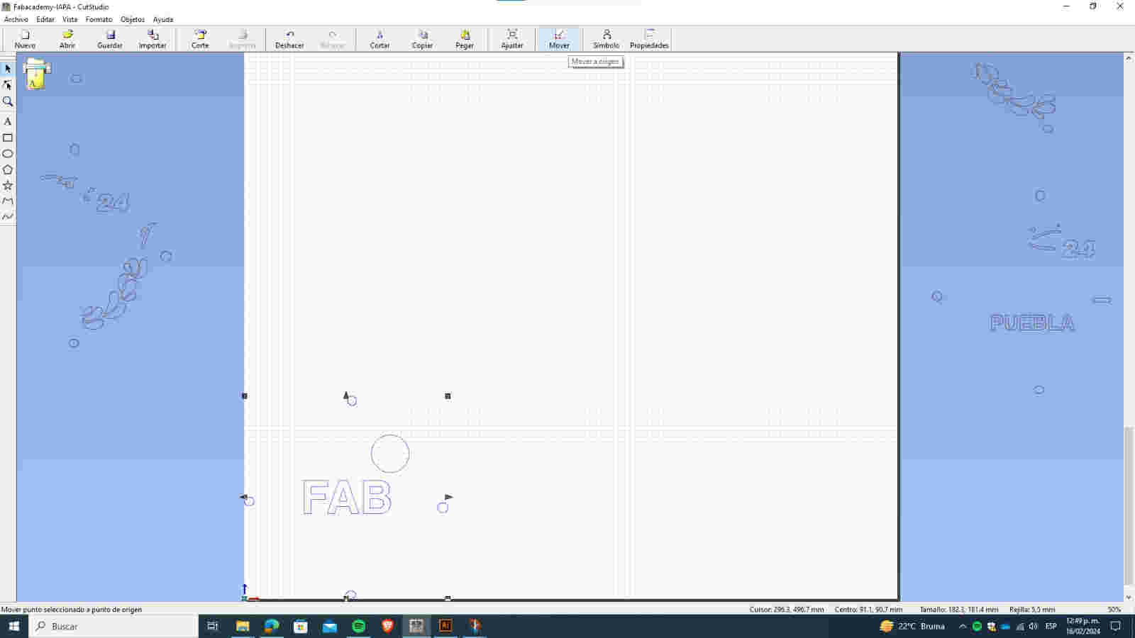
I dragged all the sections outside the work area to organize them before starting the cut.
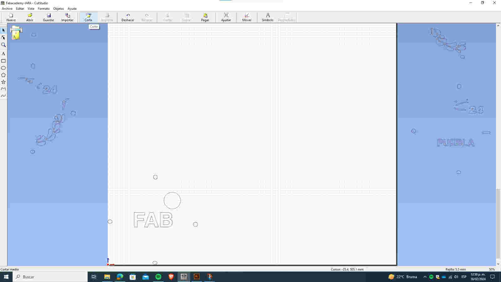
I clicked on the cut option
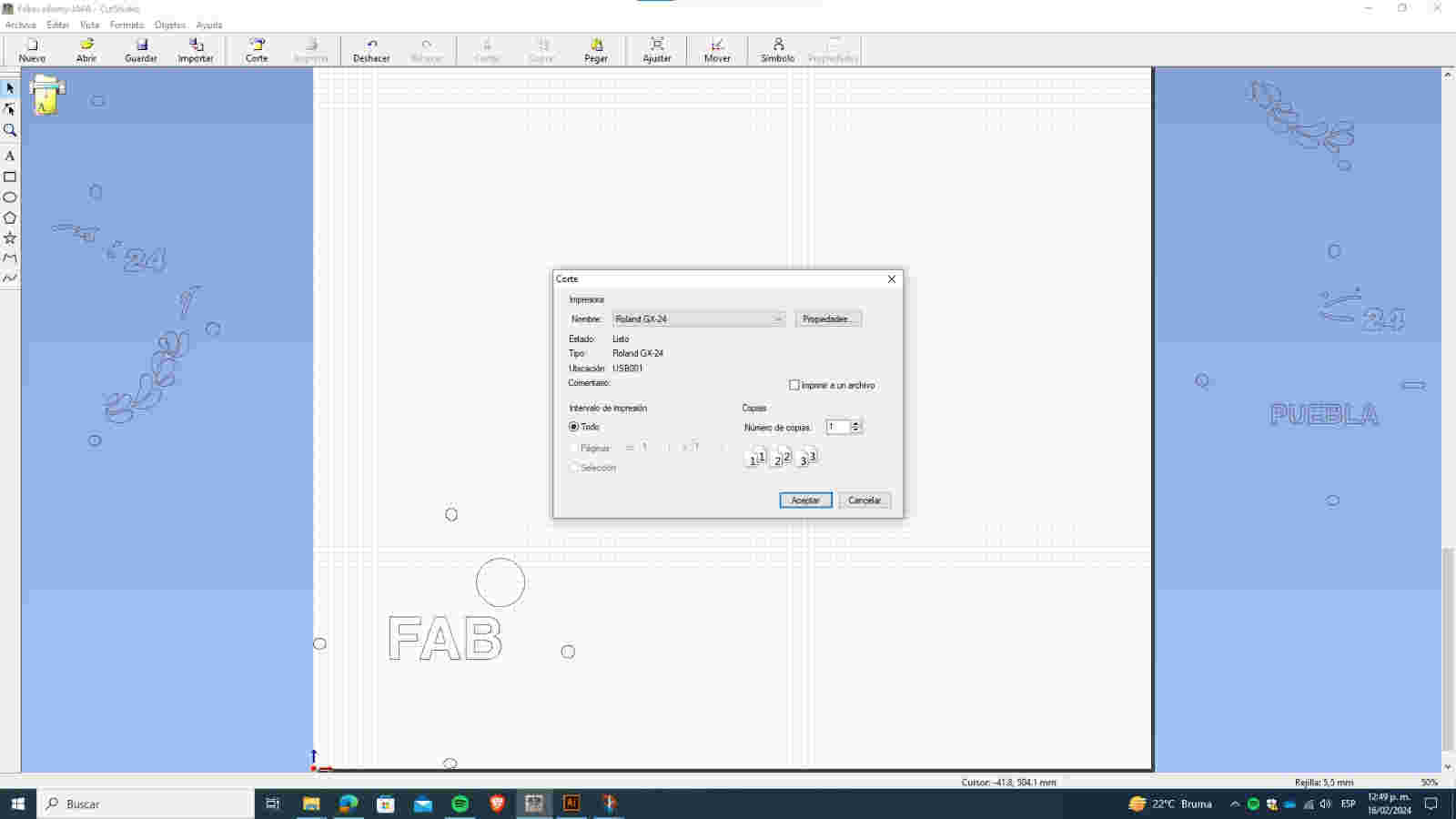
Selected the Roland GX-24 printer, and set the number of copies to 1.
Now I will repeat the same process for all sections, changing the color of my vinyl roll until all sections are cut.


Once all the sections are cut by color, I will join them using a transfer and stick them onto a base.