The Wonders of Output devices
Sounds, imaging, there's a lot to do!
My idea for this assigment is to do a PCB that's directly related to the final project, essentially it will be a buzzer module that interacts with the project's main PCB by receiveing its MOCAP (motion-capture) data (X and Y axis angles) and making a sound whenever the user moves it on a certain range of values.
Since I'm not able to assemble the PCB board as of now, I am creating this schematic with the Proteus designed tool to give a certain sense of resemblance to what the device might look like once it's physically developed.
Proteus is a platform that allows the user to design schematics and also PCB boards, bringing it with simulations and coding into give you an idea of how the devices are going to act once they are assembled.
Sadly, the free trial version needs a educational license and does not allow to save files, but I'll be making an effort into looking for someone who has a Pro license so that I can save the schematics I and post them on this website.
Here is the code I'll be using.
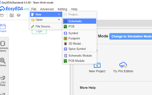
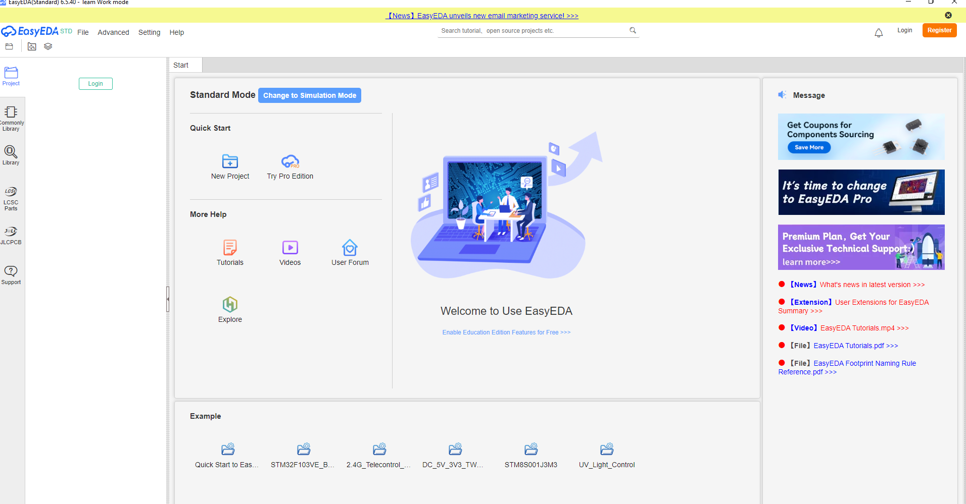
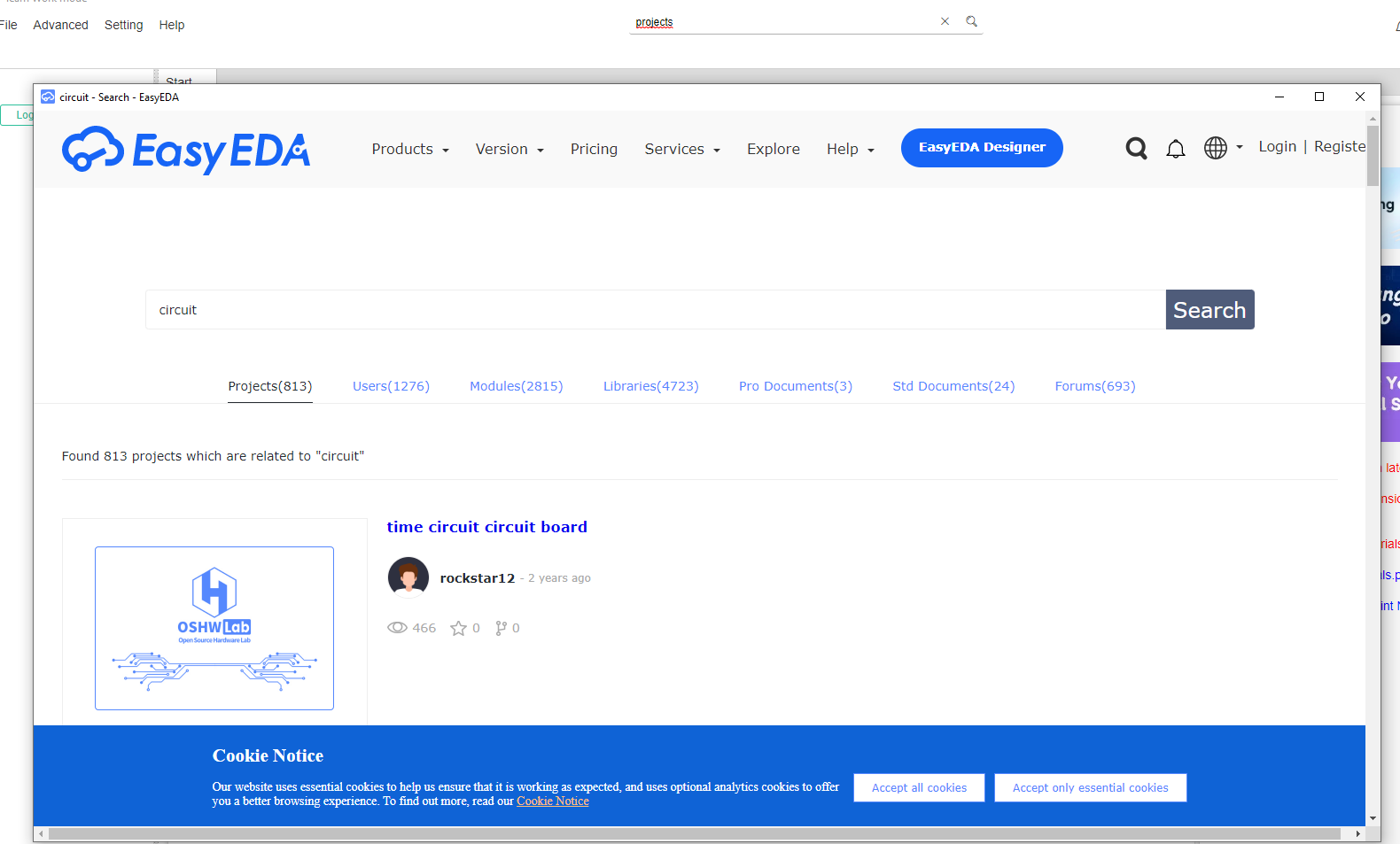
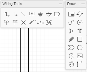
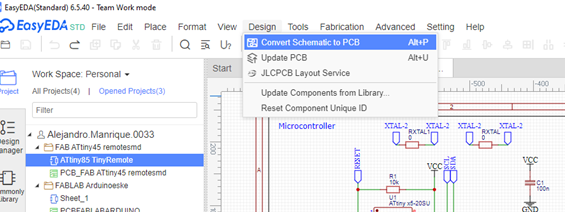
After creating the schematics and seeing if the code is properly working, I move on to the EasyEDA platform in order to create a proper PCB design that we have already done previous instances in order to save the proper file format that's going to be loaded into the CNC PCB development machine so we can be cut and traced in the nearby future.
This is how the design is going to look like.
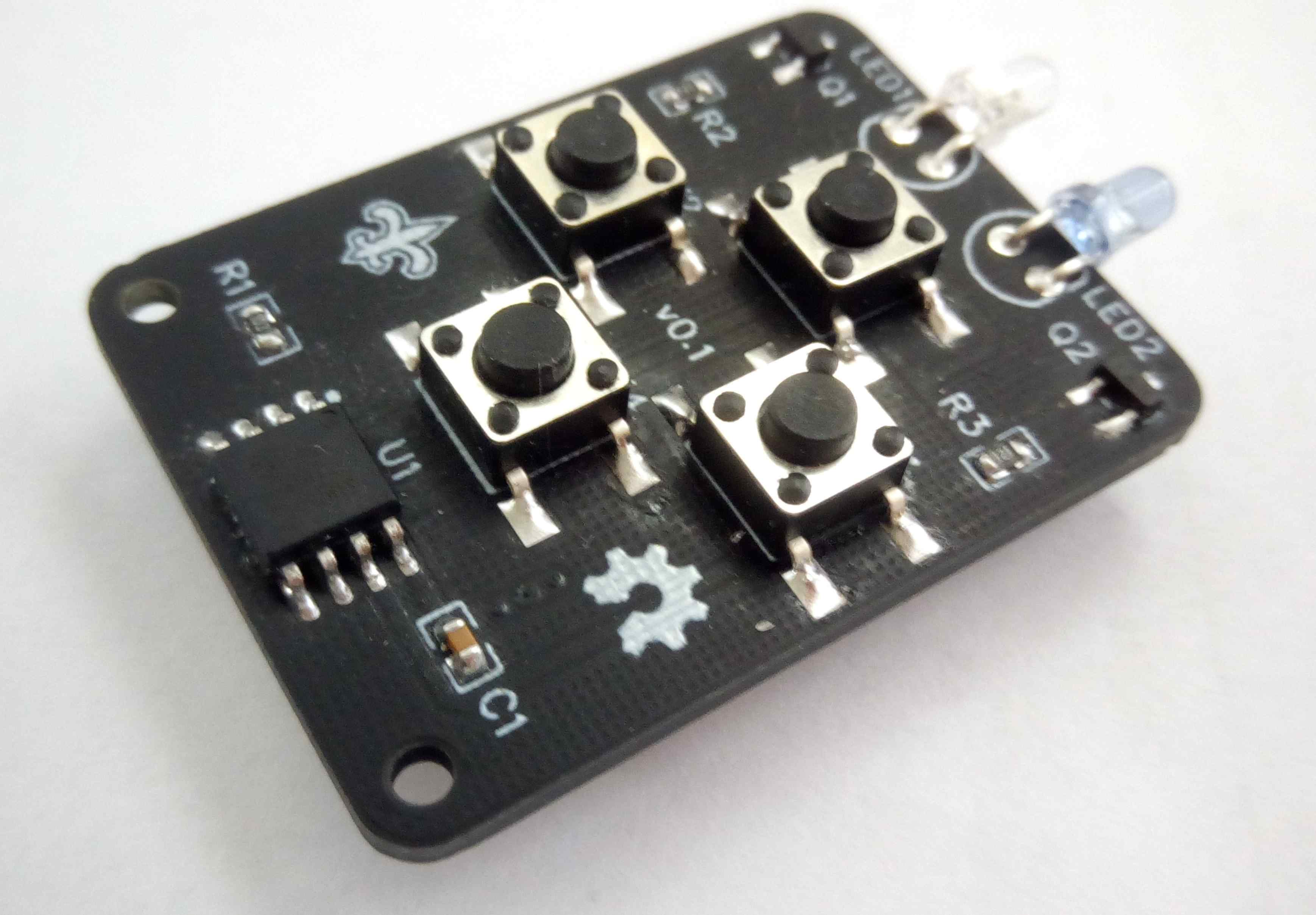
And this is how the board eventually is going to turn out with little bit of soldering and testing.