Work, work, work
How to program your PCB in 5 easy steps.... maybe more
We have a PCB device ready to be programmed, we have all the components necessary to start our journey into coding, so we will begin with something simple.
The XIAO RP 2040 microcontroller device is naturally programmed to be coded into Arduino language, this language is very simple and it allows us to comprehend certain basic functions that are done in everyday coding. To begin testing our board we will use a basic code that resembles a blinking motion so that we can confirm that every part of our board is functioning properly, what this will do is flash the LED lights we have soldered, energy will be delivered from the microcontroller into the proper channels for it to travel and into our components. This is the code that I will be using.
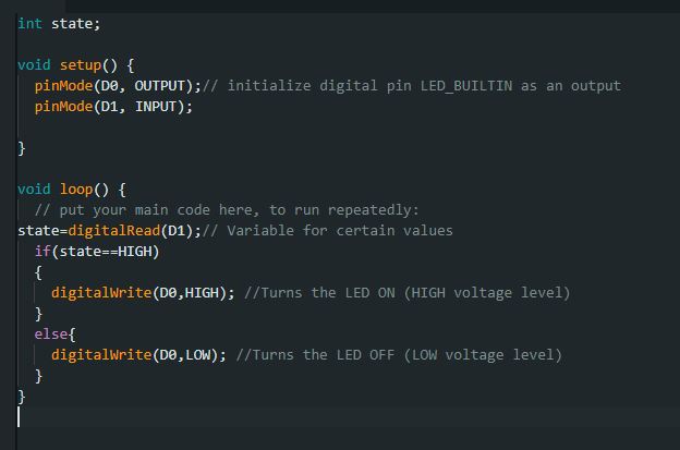
Now, if everything is properly working, then you should see Flashing LED lights as soon as you upload your code into the microcontroller through the Arduino programming platform. The board should be connected to your computer in order to draw power, and every time you connect your device into a source of power that program will run automatically.
But let's say you want to program into another language such as "Circuit Python", this programming language is also very simple to learn and it actually offers a bit more of a relaxed view on coding as it doesn't have as much of the syntax rules as Arduino or C+. There is a way for you to actually change the programming language in your microcontroller through an easy option, this consists of using this file (ONLY FOR XIAO RP2040), copying and pasting it inside of the device using your file browser. After doing so, your control board would actually switch programming languages and automatically will assign its own name to CIRCUITPY. This basically means that the previous Arduino device was disconnected and then a circuit python programmed device has been connected into your computer, but don't worry, resetting it would revert it into its Arduino natural state.
After setting up the device to use the circuit Python language we need to download the proper programming libraries that are used for coding, you can find those libraries by clicking here. This would direct you to a website that will help you download all of the library packages you might need to program in circuit python.
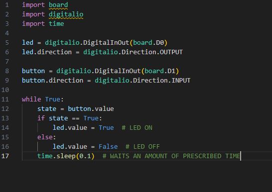
After downloading the proper libraries and pasting the ones you need inside your library folder within your CIRCUITPY device, we can code freely without worrying about compatibility issues. Actually, I'm going to leave the previous code we uploaded with the difference that this one is in the circuit Python language.
LED Galore... kinda
In this section I am going to discuss the code that I made to create a sort of light intensity device that allows me to control the intensity of the LED lights of the board using a potentiometer that was soldered into a different board. I initially used the Arduino language so that I can have an easier time programming and confirming that everything went as planned. Here is the initial code.
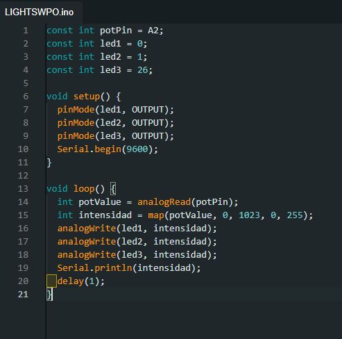
So, a quick explanation to what this does is: firstly, we declare the proper variables that we will be using, in this case the first thing we need to declare is the proper pinout structure that would identify the input and output of our circuit. As you can see, we use the LED ports to identify the inputs and outputs as well as the potentiometer location. After that, we set up a loop function that would read the outer geometry raw data and then interpreted into a range of values that would allow us to assign a digital input into the LED devices, this makes them adjust their light intensity to whatever value the potentiometer gives them, and that value is given by the turning of the physical component with our hand.
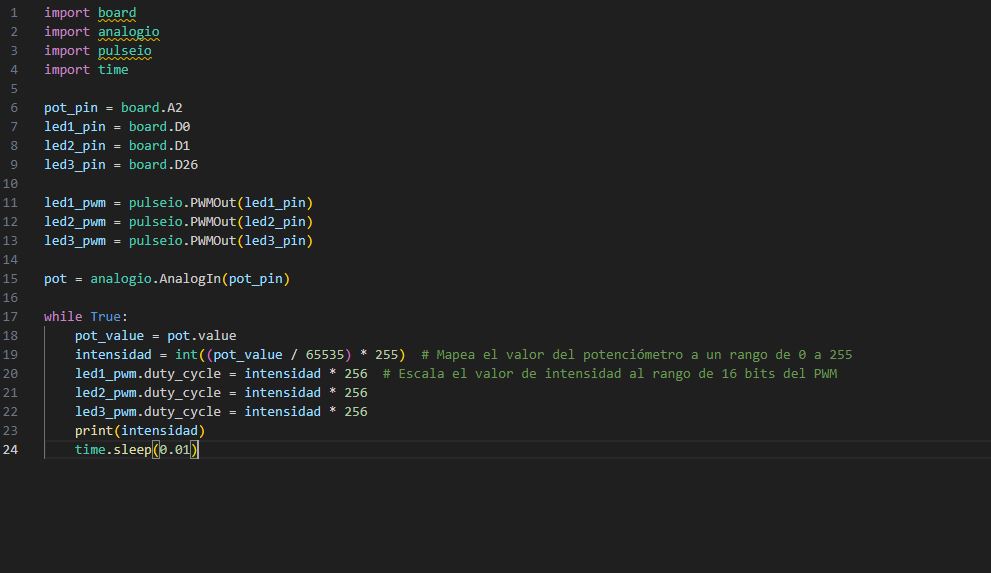
And here you can see the circuit python code that I translated if you wish to use it in that programming language.
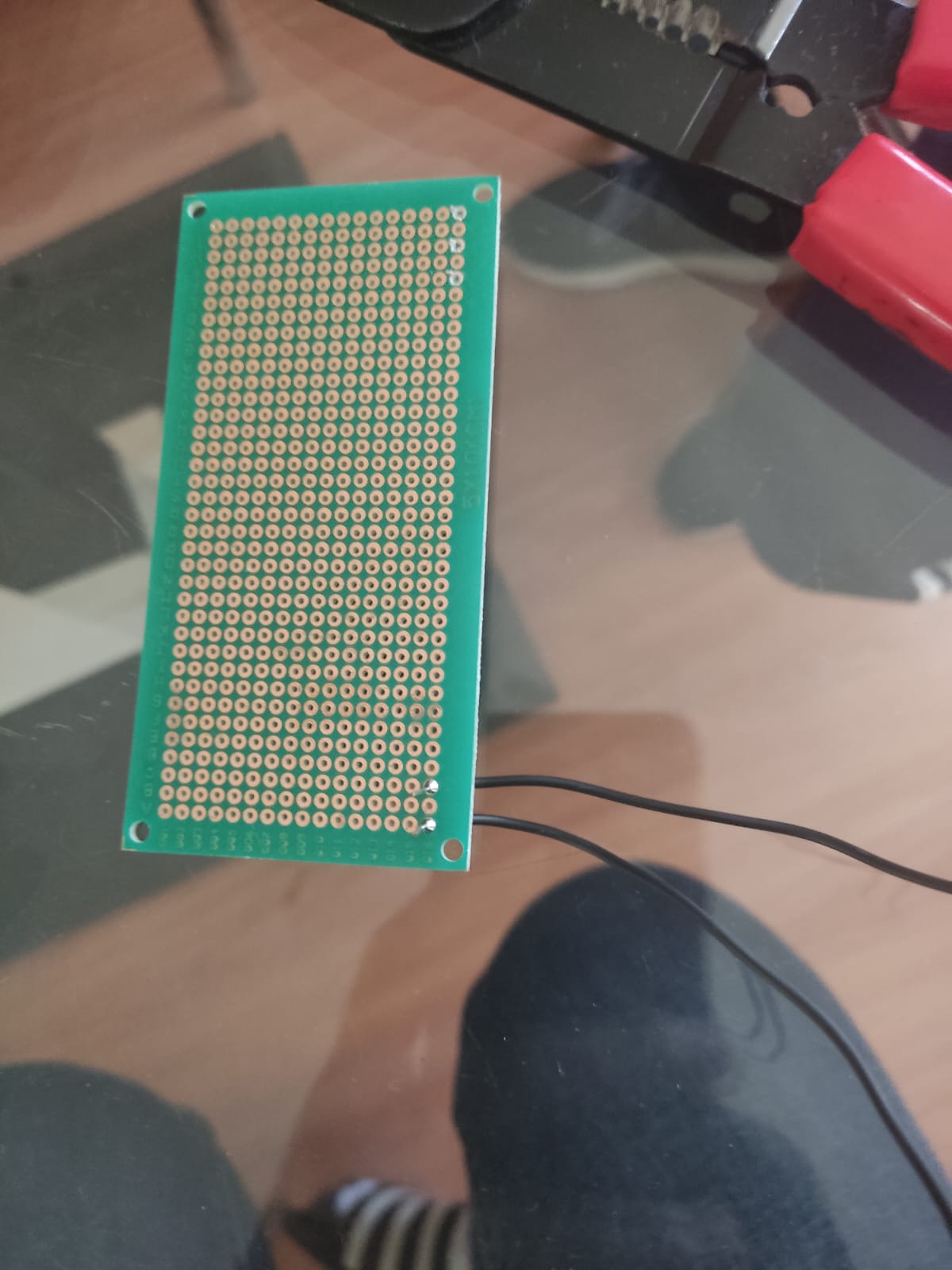
With the programming out of the way we can proceed into the physical part of what the device should look like, additionally to the components we already have within the PCB we would add another PCB board, although this one is different, with the potentiometer and the proper communication cables soldered into it, as you can see there are three different cables: One is for the communication, the other is for the voltage needed to power up the potentiometer, and the last one is the ground cable. This in turn are then connected into the circuit to send all of the data to the microcontroller and run the program as it was intended.
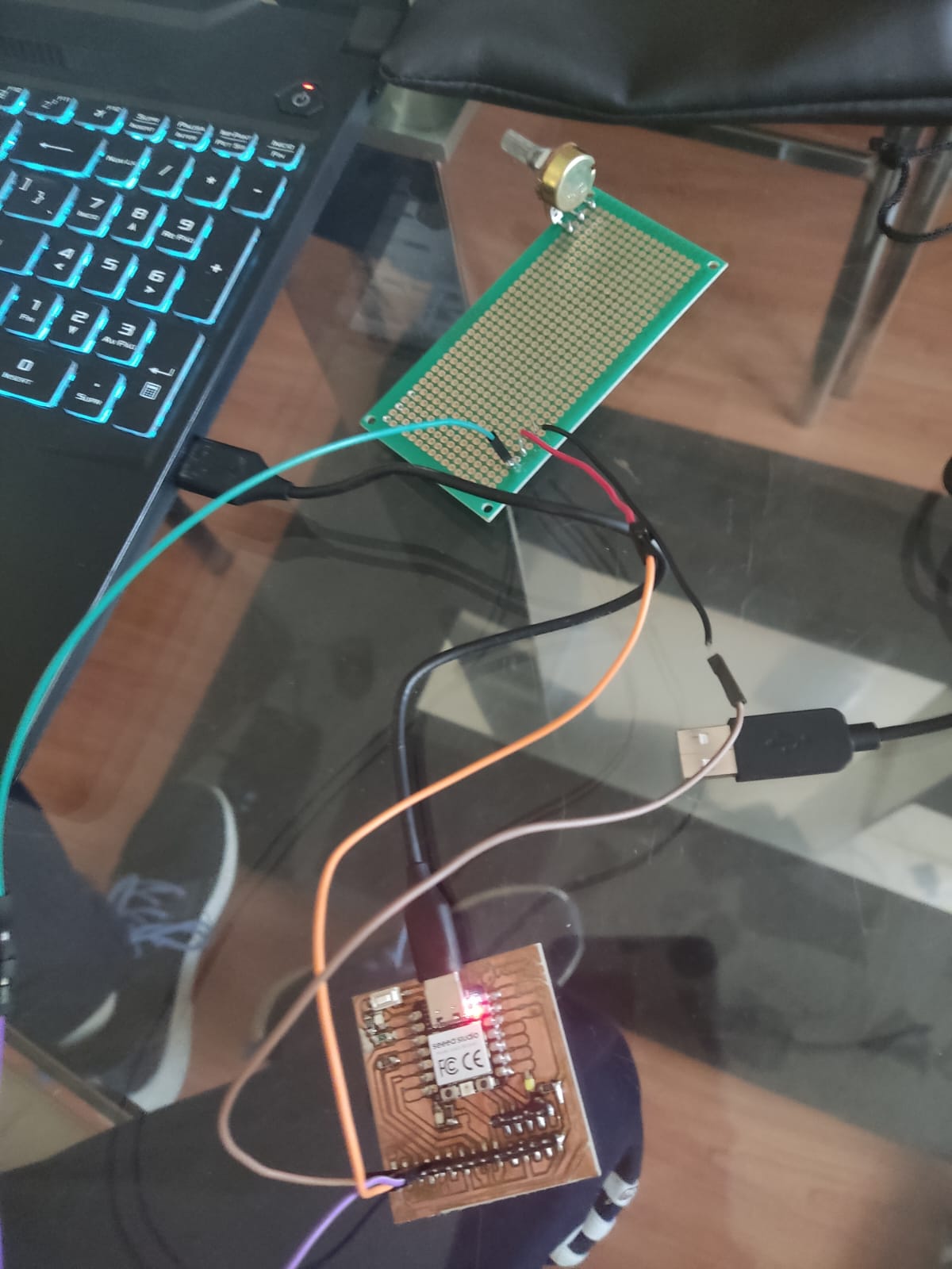
This is the result of what all I've been saying, a light sensitivity circuit that resemble some of the lights you might see and somebody's house or a place of business, granted, this was much cheaper to do.