Copper!? Are we going to a scrapyard?
That's right! We are doing some work on some copper plates, specifically, we are creating a brand new circuit design.
Setup & Cut
Before we get excited, let's make sure we have what we require in order to bring our circuit to reality. Firstly, we need to install two different software tools, Vpanel and our CNC milling machine's drivers.
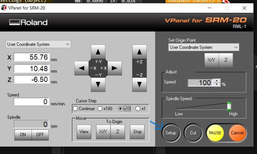
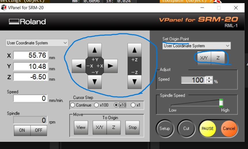
Now, let me explain what Vpanel is: Basically, it's a controller used in the cutting and engraving process that guides our machine to do what is necessary, What do I mean by this? It's a panel that contains certain controls that move our tool in the process within the machine's parameters, it's a console that can set the points of origin and three different axis and load the routine that the CNC machine is going to perform. Then, there's the drivers, these are files that once installed, interface with the machine so that we can use VPanel.
I'll leave both the files for you to install here and here. Mind you, the driver file is specifically made for Windows 10 within a 64 bit system due to being the system I am using.
After installing the software required for using the CNC mill machine, we need the file to begin our process, for that you need both of these. Those are the cutting and engraving files we used to create our circuitry. But wait! You need to visit this website.
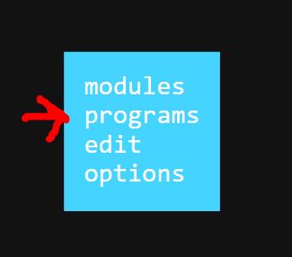
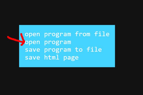
If you see a black or blank screen as soon as you visit it, don't panic. The only thing you need to do is right click so that a tiny list may appear, after that happens, you need to left click on the programs section, this will open up another list with a set of options, for our particular case we are going to click on the "open program" option. This in turn, will generate aaaaanother list, quite the dreary process, don't you think? But don't worry, I'm here for you. This list contains a number of machines and options tailor-made for specific needs. We are going to look for the "Roland SRM 20 PCB" option as this is the machine I'll be using.
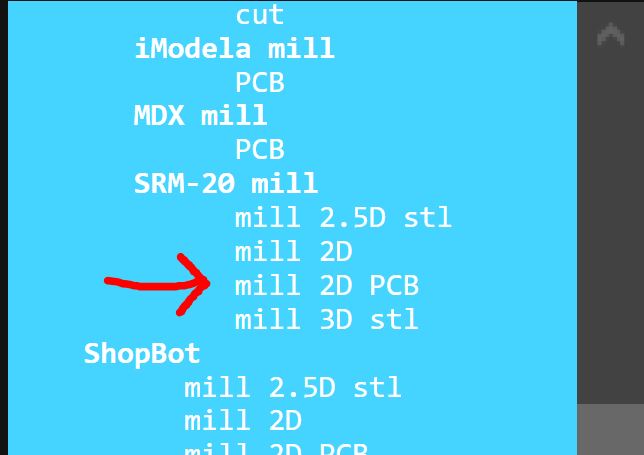
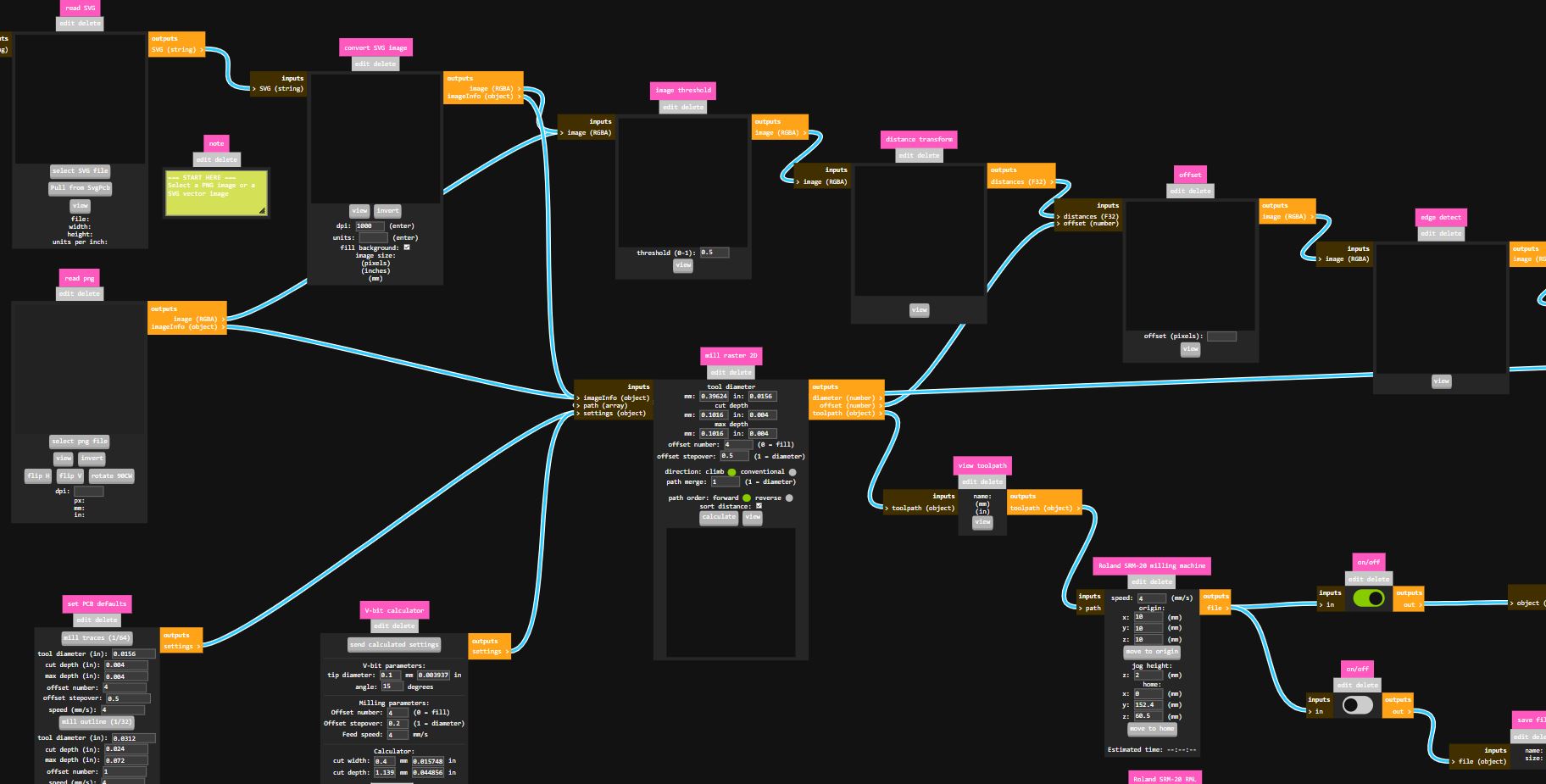
This shall open up a giant tree consisting of several different sections, but the section we are going to be interested in is the one that consists of Mill raster 2D and it's add-on sections. So what do we need to know? Well, the first panel allows us to import a .png file of our choosing, obviously we need to verify that the file we are using is black-and-white colored, but why? Well, black and white images are used by the Milling machines to identify the places they need to cut or engrave and the places they are not so. So this means that the white spaces in our image are used to point out the routes our machine needs to follow, keeping the black spaces free of any alterations and, if you notice there's an invert of button that "inverts" the colors to work on different spaces, there's also other buttons such as flipping vertically and horizontally our image as well as rotating it.
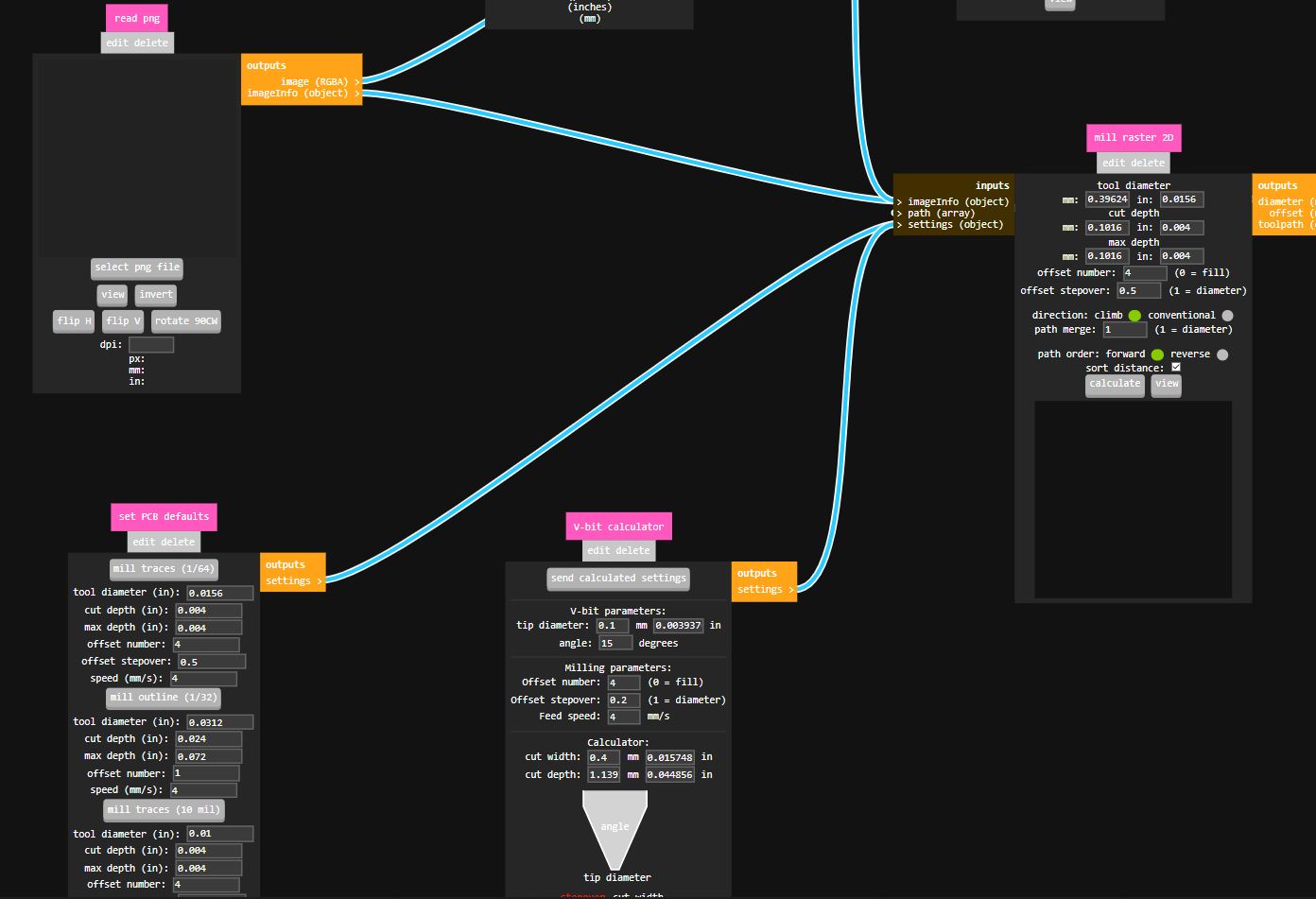
So, we have imported our .png file, but that's not it, the second and third sections contain the necessary statistics that the machine needs to follow in order to perform its task. Things such as tools, diameter, cut depth, offset number, speed, angle, etc. These sections need to be filled in relation to the machine you are using and the task you want to perform. You have to be really careful, wrong number here and there may cause some damages to your machine, to your workpiece or to you, so make sure you get to know your machine and make the proper adjustments.
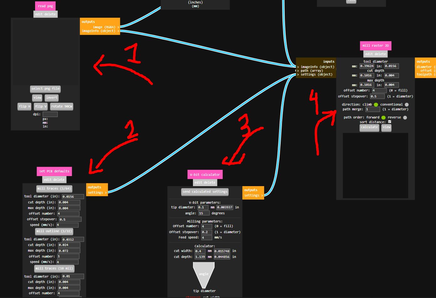
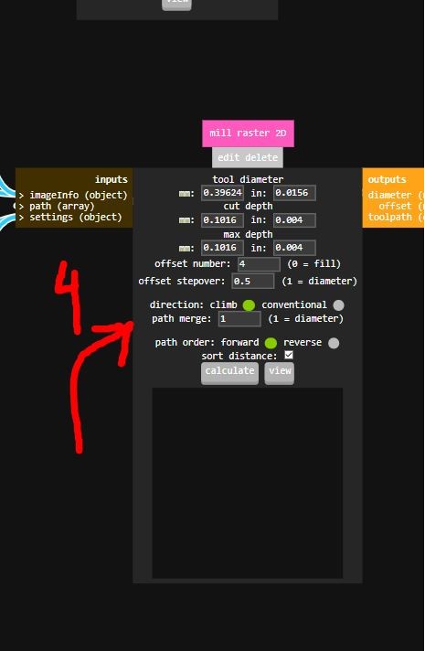
Now that the calculations have been declared we send the calculated settings and go into the fourth and final section, in which we are to make the final adjustments. After being certain that everything has been inserted as it's supposed to be. We press the calculate button, this will create an image or a rendering image that will show us how the process is going to be done, it's a way to be certain the process you are trying to do is the correct one, and by pressing the view button we can get a closer look on a new tab on our browser.
Then we download the file generated by the program.
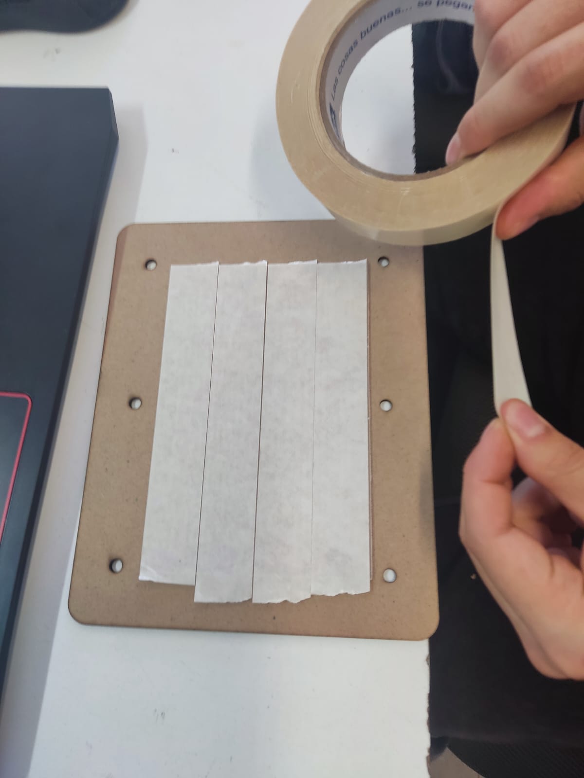
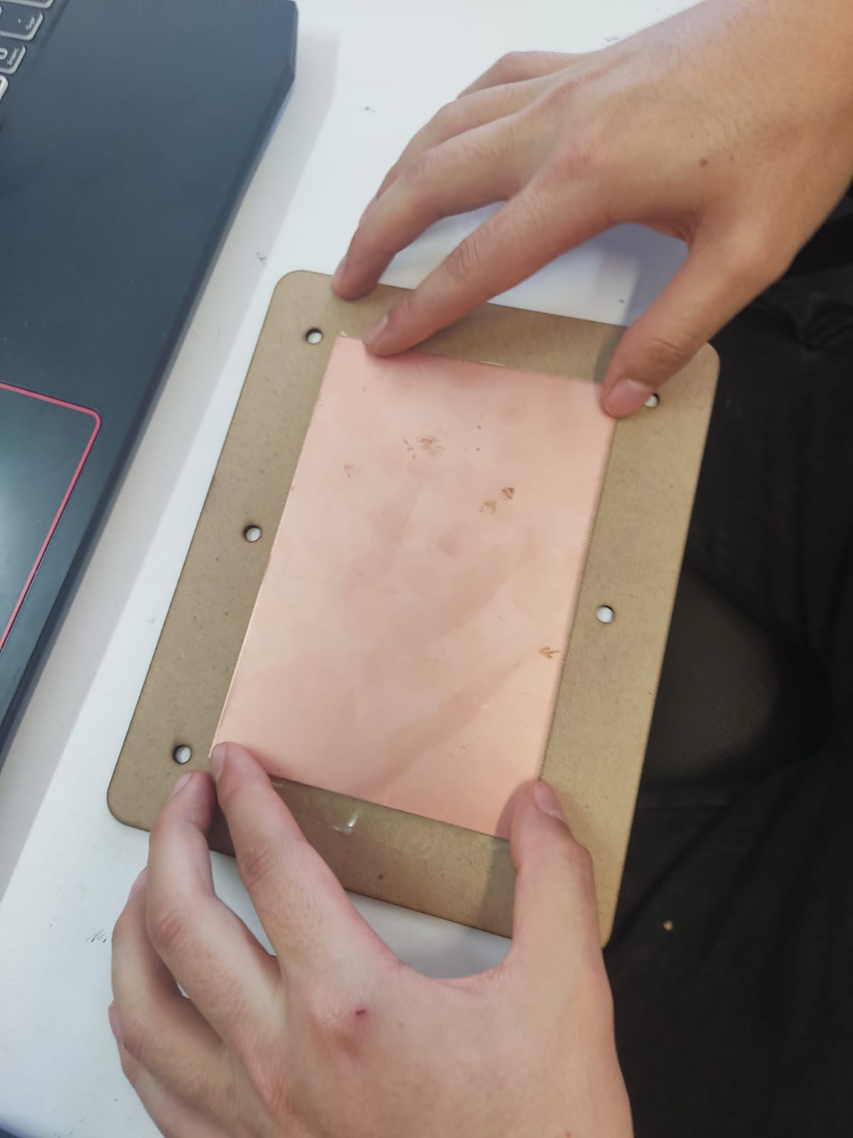
After doing that we need to prep our copper, firstly, we laser cut a "sacrificial" plate out of our preferred materials such as MDF. We need to create a design that contains holes for the screws that are used to place it onto the milling machine, and it has to be thick enough to withstand the vibrations and cuts that the tool is going to generate, then we place our copper plate in the middle using an adherent material such as adhesive tape, the double-faced kind, in order to create an adhesive layer between the copper plate and our sacrificial plate. We then place it on the machine, screwing it in place, and connecting our computer to the milling machine. This is where VPanel comes into play.
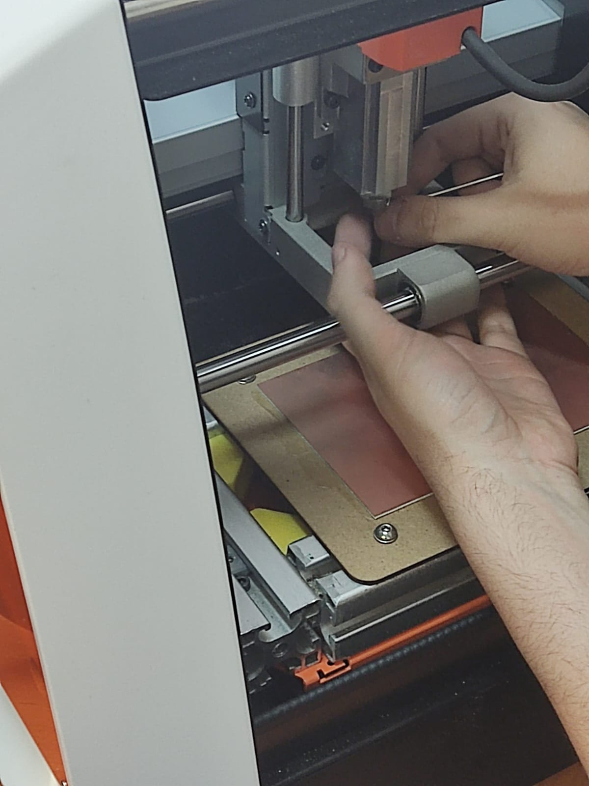
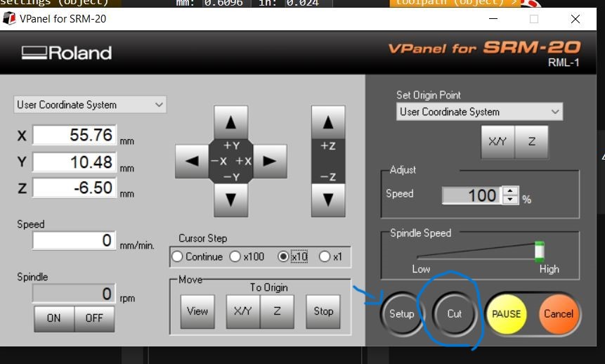
Before we can turn the machine on we need to place the tool for the job. This is done by using an allen key to fix the tool in place. Then, after doing so, we open up VPanel and use the buttons to turn the machine on and begin to place the origin points throughout our axis. This is done to calibrate the workspace we are going to be using and the height required to perform the task properly. After placing the tool in the preferred origin point in our three axis we use the origin button to record those coordinates so that they can be used at the moment of manufacturing circuitry.
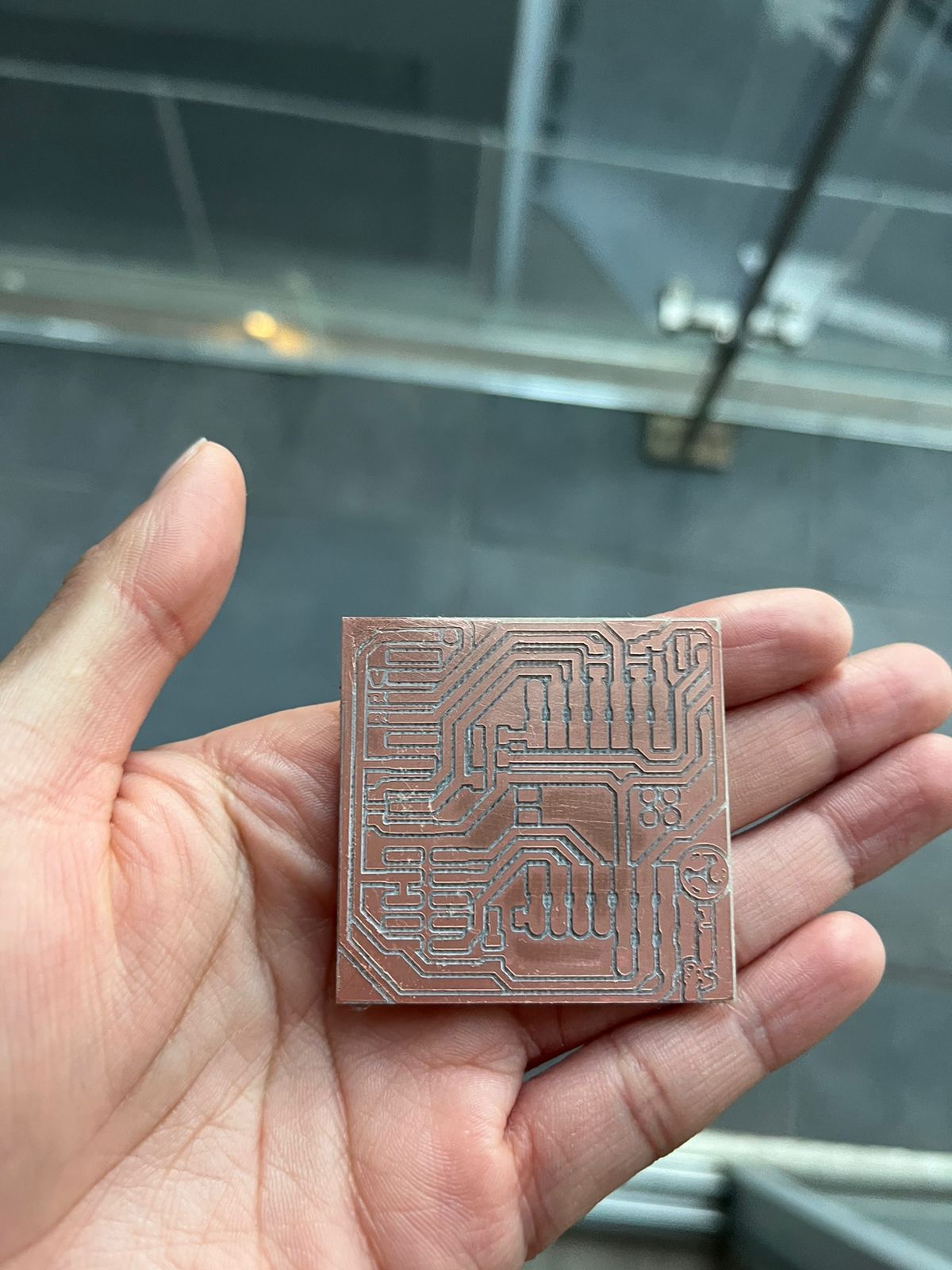
We then put the tool away from the plate, open up the file we calculated on the website by presssing setup and then selecting it, press the output button, and begin the process by clicking the cut button. Now, you need to be careful as this process takes about 25 to 30 minutes, any inconsistencies in movement, vibration or sound should be evaluated in order to stop the process if there's something wrong going on. So, after doing all of that and repeating all of those steps for The Cutting process we have our circuit, the only thing needed to make it look like a proper circuit is beginning the soldering process.
Soldering & Testing
Soldering is quite a delicate affair, many factors need to be considered, but then again, don't worry, I got you!
The term soldering comes from the ancient Roman dialect of just kidding! We are not gonna do that, let's go over the basics [Takes deep breath], alright:
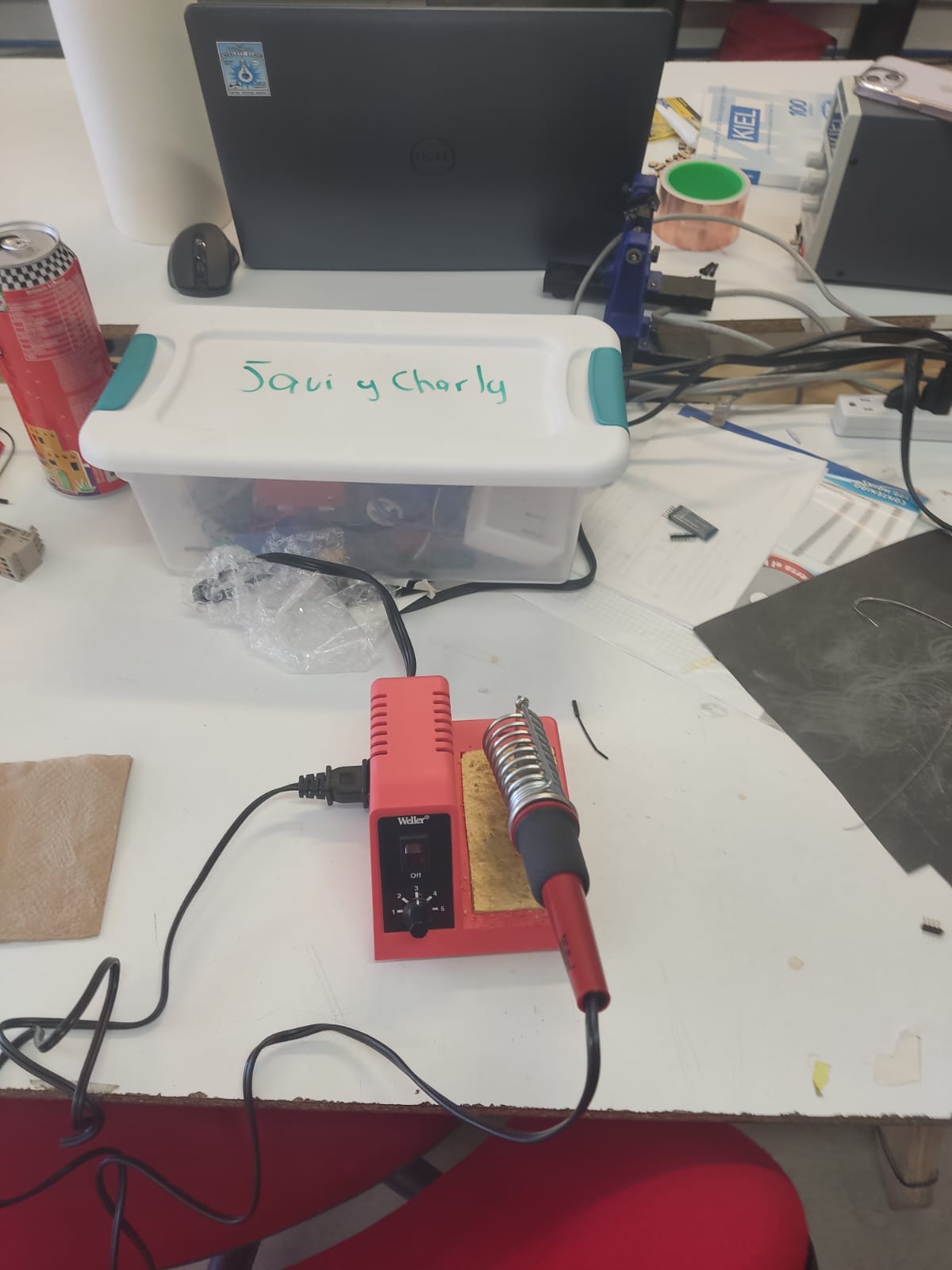
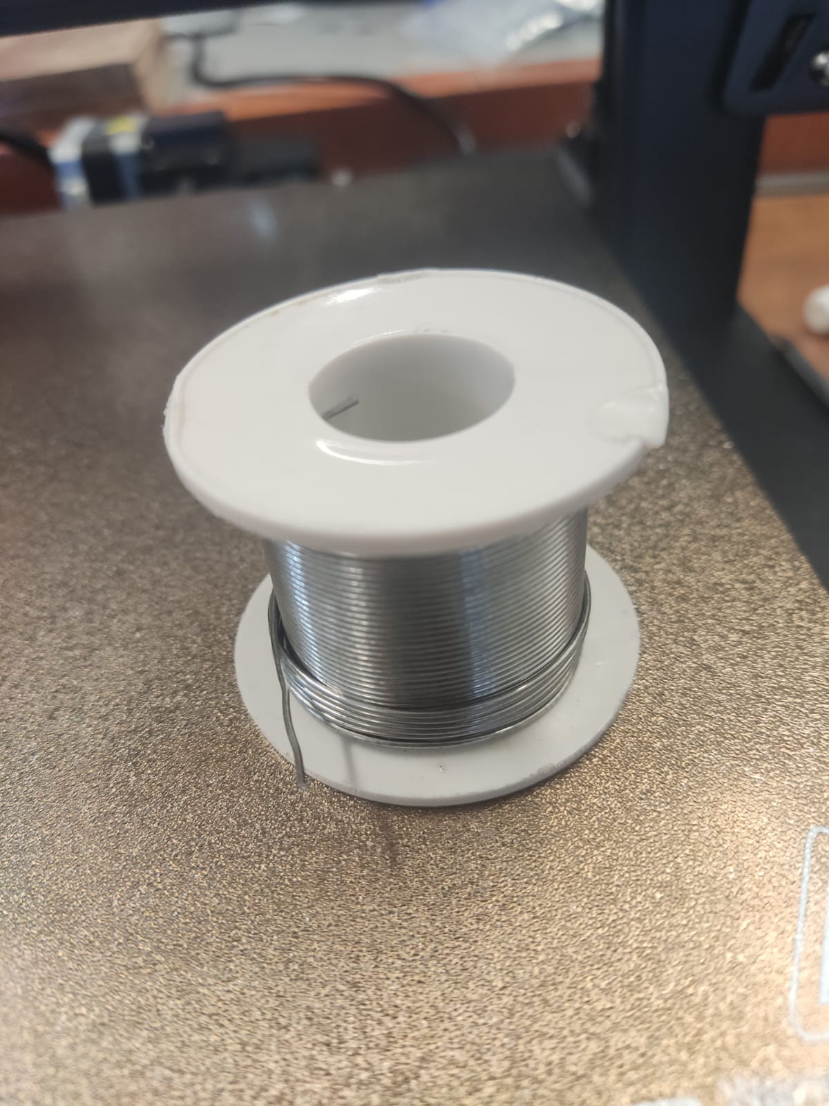
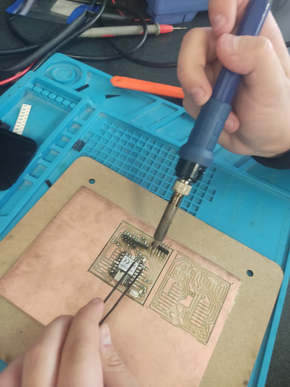
To begin soldiering we require three basic components: Our PCB, a soldering iron, and the solder itself. What is the solder? It's a small cable like thing that's made out of a metallic composite that melt when heated properly at temperatures of approximately 300° C, this happens thanks to the soldering iron that consists of a metal rod that heats itself using electricity transform into heat, there are a few things we need to know before we use the soldering iron: We need to be careful about where do we grab the iron itself, rhyming of metallic piece of that iron with our very hands will cause quite a burn, so precaution is imperative, second, we need to wait for the iron to be heated up as it is being fat electricity, and to be careful to what we point the iron against to, as it may melt anything it comes into contact with.
Now that our iron is properly heated, we carefully and calmly approach the PCB with the iron on one hand and the solder material on the other, we place the component we want to solder into the PCB plate and use the previously mentioned items to fix it in place, the iron will heat the soldier material and the soldier material will be begin to melt and then attached to the copper, solidifying itself quickly once the iron is removed, the proper way solder a component is to insert both materials in the following order: Soldering iron first, then comes the solder material itself, then we remove the material and finally, the iron. The shape of the soldering material that has solidified in our PPD shall look something resembling a tiny mountain, be careful not to spill too much material as it could cause shorts and connect other components that are not supposed to be connected.
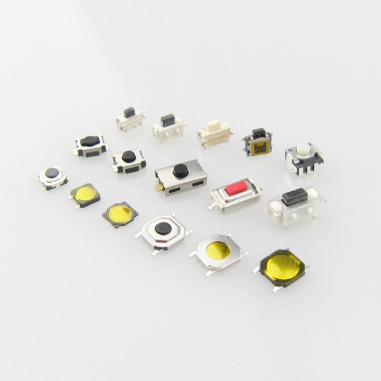
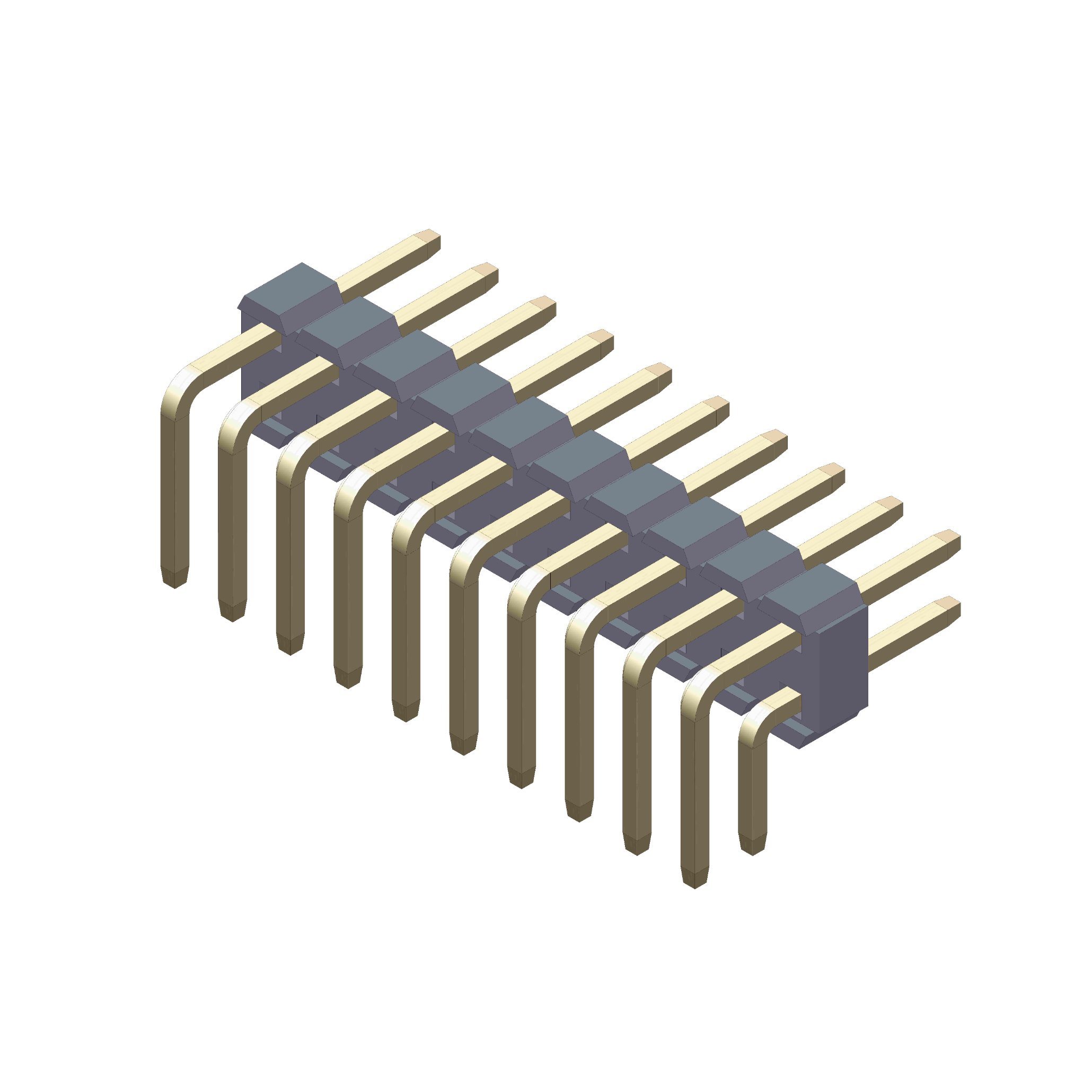
So that's the basics stuff dealt with. Now, you need to get an idea of how we're going to solder our circuitry, we need a reference. So I'm using these images as a reference to know what components I need and where do I need to place them.
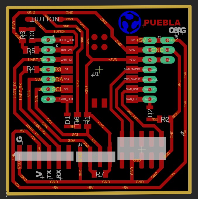
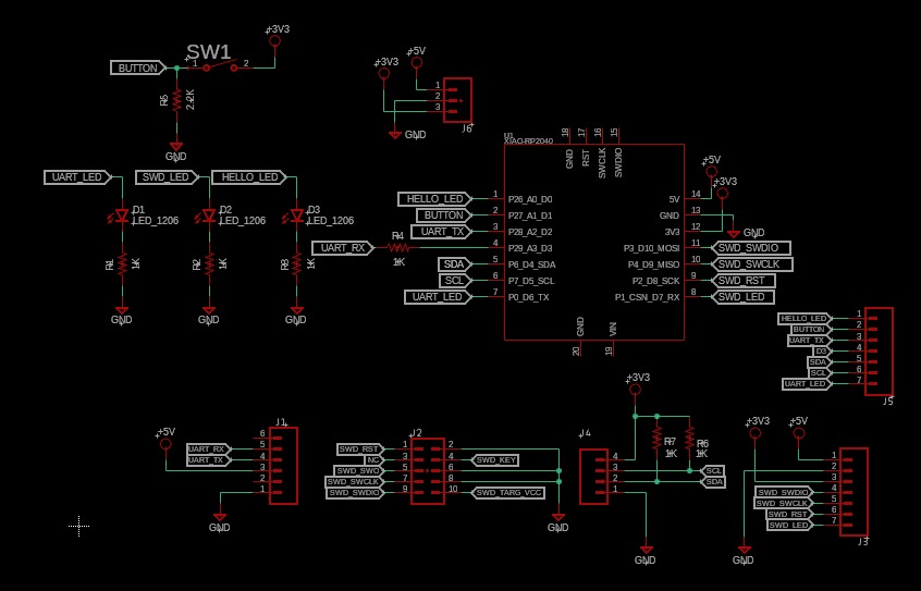
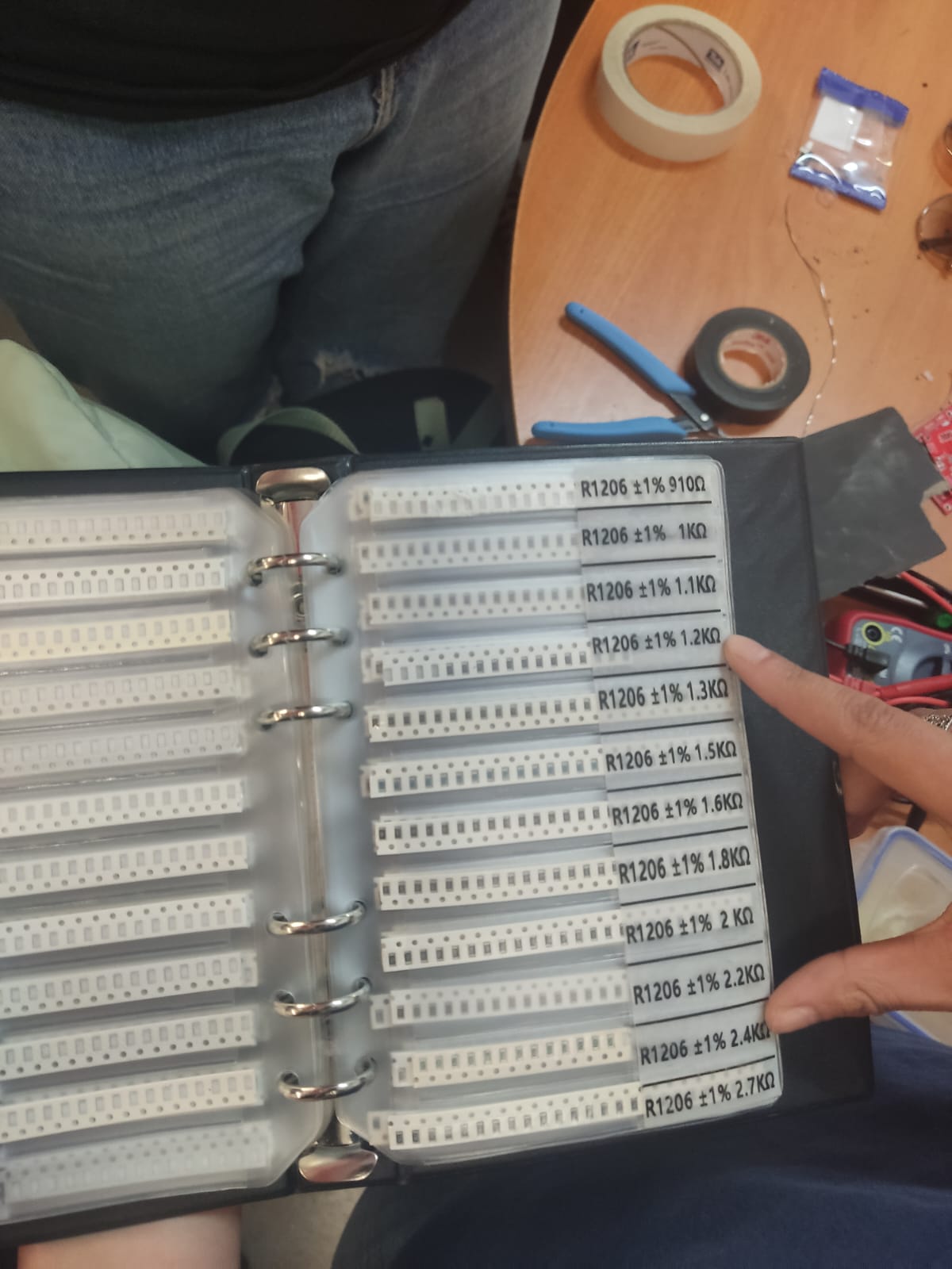
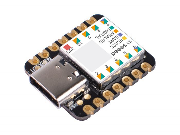
The components we are four 1.2 kiloOhms resistors, one 2.4 kiloOhms resistor, a tiny button, three LED lights, some headers (about 20 or so), and the controller/processing unit which is a Seeed Xiao Controller.

It's time to solder, be careful of not spilling the soldering material over the edges, creating bubbles, and using insulating material for the controller unit to avoid any shorting issues.
In the end your circuitry might look something like this.

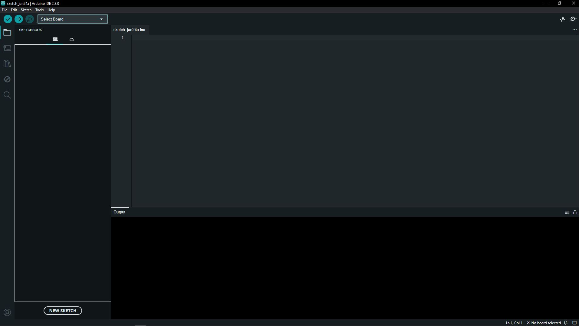
We are so close to finally having something that we can actually code in and generate programming. The final steps involve installing the Arduino coding platform and obtaining a USB to Universal C connector cable. Thankfully, the Arduino website allows us to download and install their proprietary platform, the cable is quite common.
The Arduino programming platform looks something like your basic programming studio, it's a place where you can upload codes, open different files, generate new ones, install drivers for different devices, amongst other things.
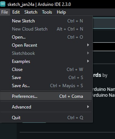
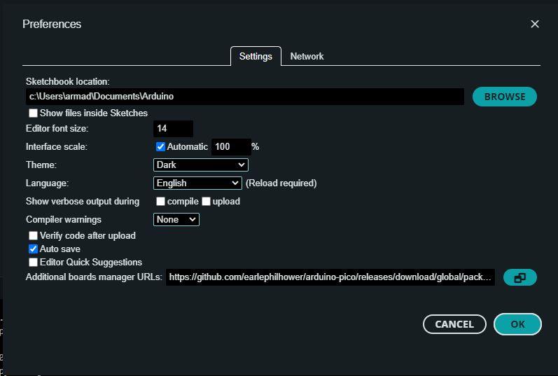
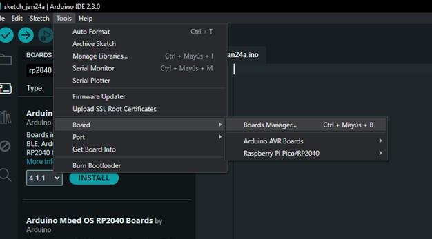
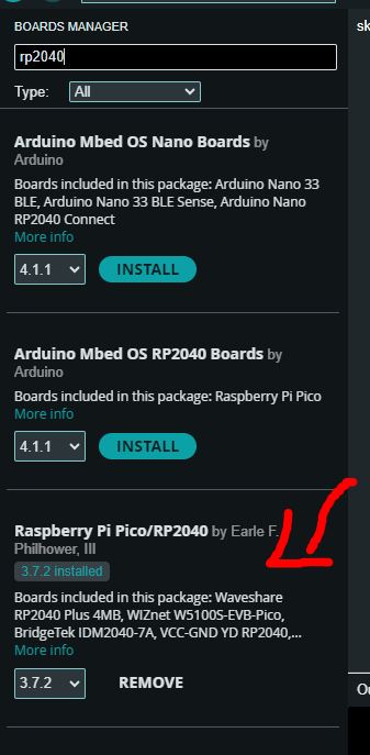
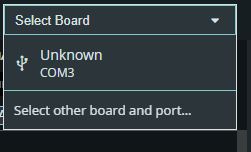
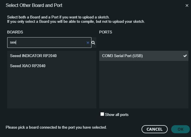
After opening the Arduino platform, we go into the preferences menu, in here we are going to use this URL to insert it into the additional boards manager text bar, this will allow us to access the Xiao's drivers that are responsible for enabling us to be using the controller with the Arduino software. We press OK and then proceed to the "tools" menu, into the "board" option, then clicking on "boards manager", this will display a list of different boards we can install the drivers for, we look for the RP2040 option as it has all the necessary requirements to use the Xiao, we press install and wait for it to download.
Finally, after having our Xiao controller configured in the proper manner for the platform we select our PCB that's connected to our computer and load up the following code that allows us to test out the components that we soldered before and see if everything is working as it should be by pressing the verify and then upload buttons on the top left corner.
There you go! All done, see you next week and I hope you have a great day!