Gimme some Lego look-alikes!
Who doesn't love construction kits? Shapes that become other shapes, now that's entertainment, so I'm cutting some of those for me.
Designing the parts
So, the first step in building the construction kit was to figure out what design shall I go for. So, I went on the internet and found this image on Google Images. Here's the link.
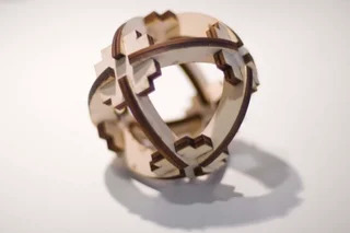
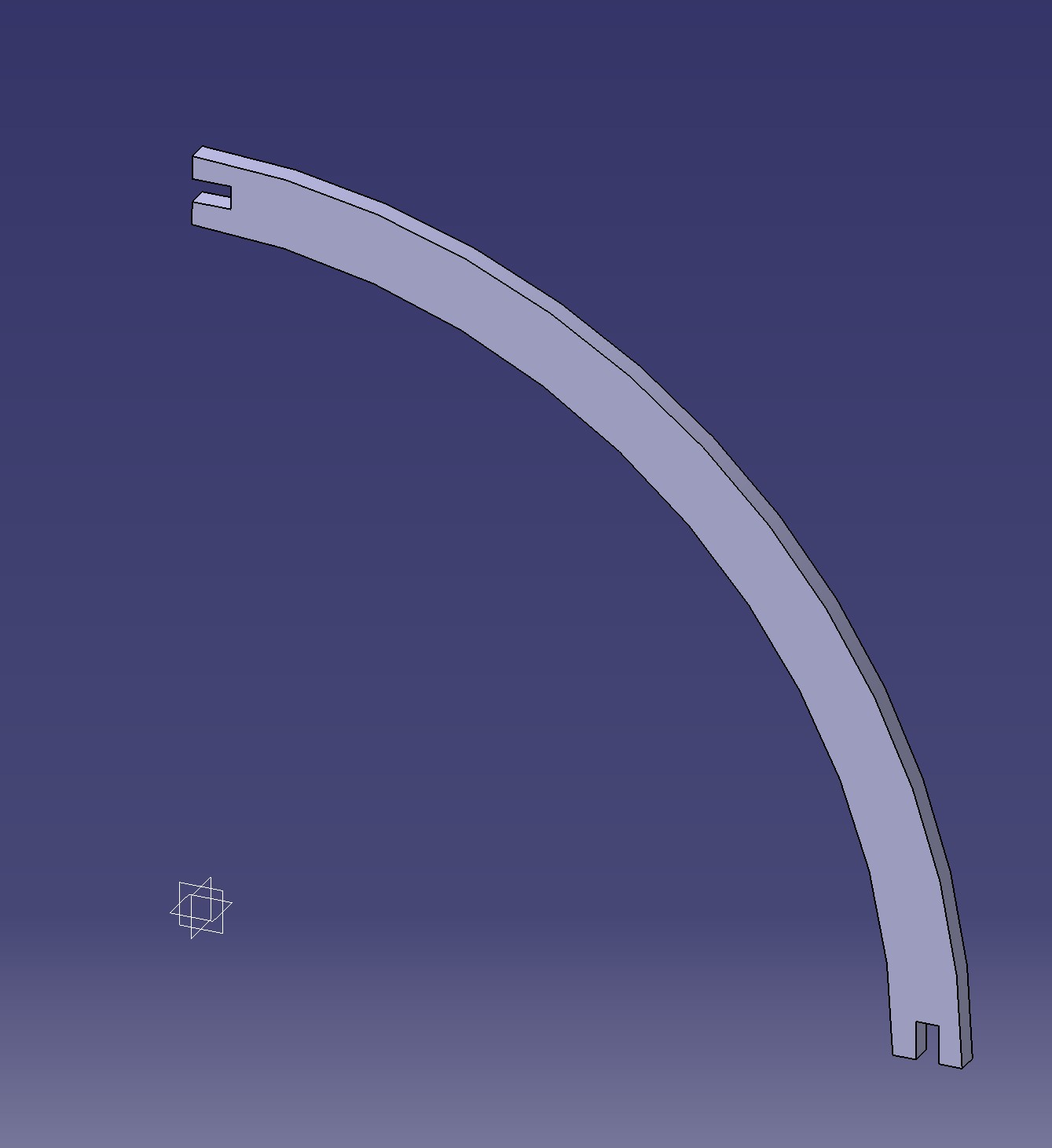
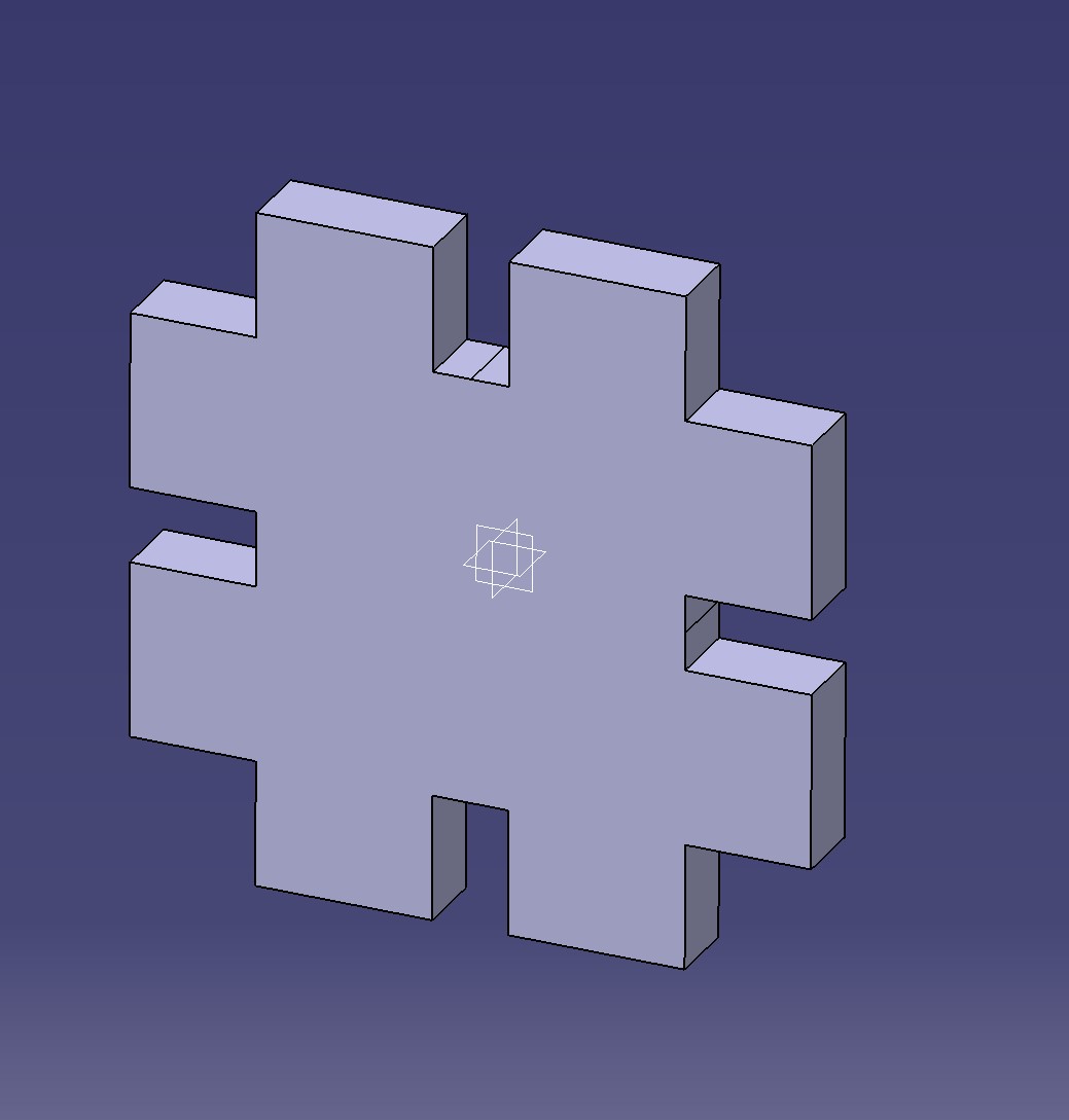
This kit was made up of two shapes: a curved link with a sorta-clamp end and a shape resembling a puzzle piece.
Now, this kit has an interesting aspect to it, it's parametric, meaning there are parameters, formulas, or equations that directly affect the size and shape of our pieces. Since I'm using the CATIA design software, there are certain steps that we need to follow in order to enact the previously mentioned feature. Here is a detailed description of the process.
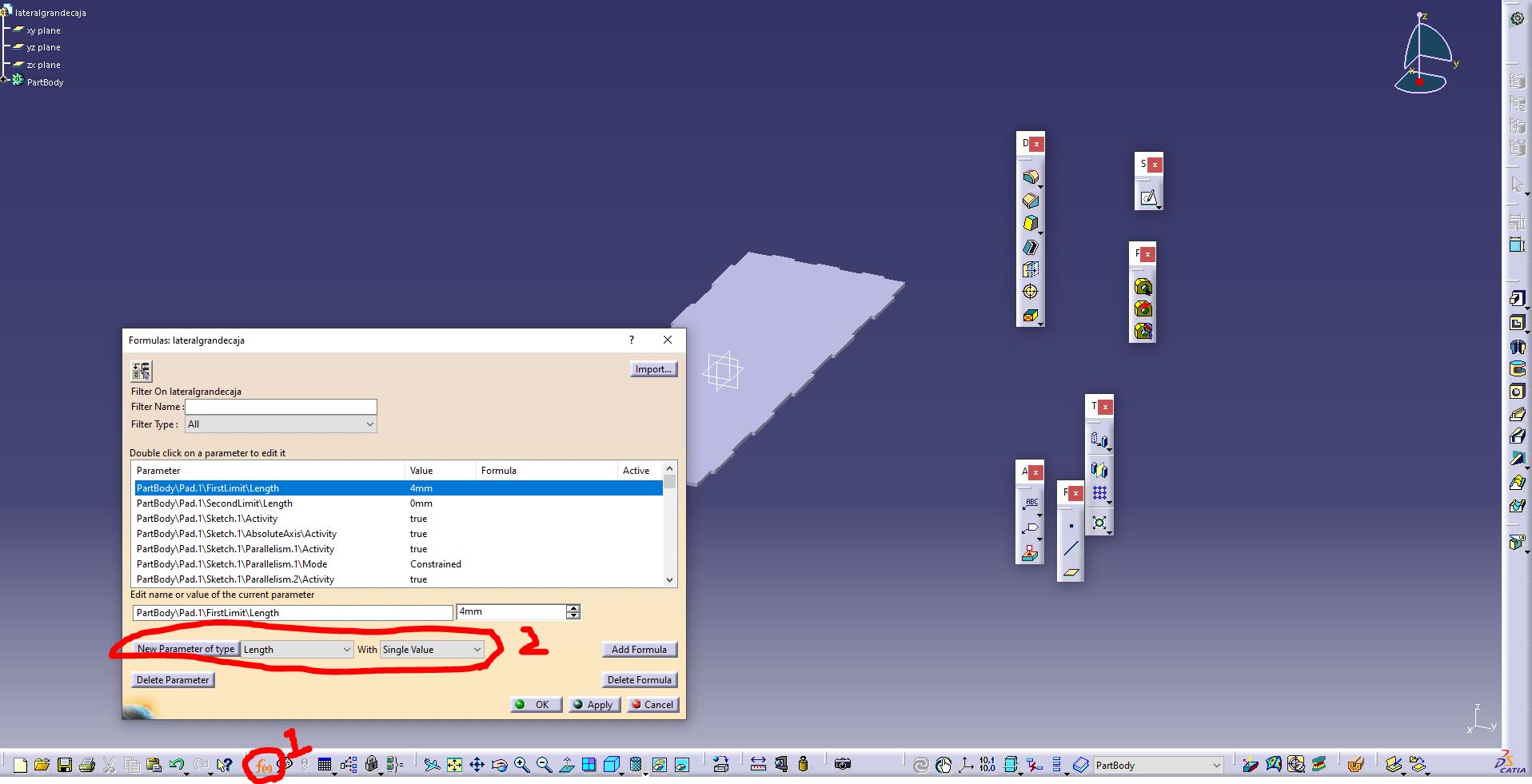
Firstly, we need to open our Part design file that we wish to create or alter. Then, after we have a drawn shape on our sketch we select the icon that allow us to insert new parameters. Here, we can see all of the parameters that reside within our file, we also are able to insert new ones, choosing the type of parameter aswell as the type of value we want.
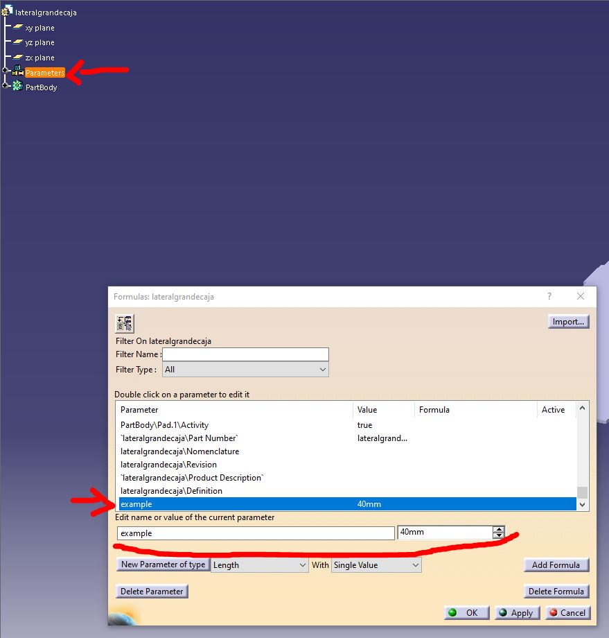
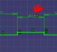
In my case, I inserted a parameter with a "length" type and "single value" option, this was done by selecting the "New Parameter of Type" button and then left-clicking said new parameter and editing it using the area below the list to name it "example" and establish it's value at 40mm. You can notice that the parameter was successfully created by the creation of the parameters section on your work tree at the upper-left corner of the screen.
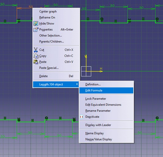
After that's done, we enter our sketch and select the constrained dimension we want to alter with our newly made parameter, we right-click and head for the "Edit Formula" section. Once we've done that it's just a matter of selecting the parameter type in the list in the middle and look for our custom entry in the right-side list, double left-click on your "example" entry and see the parameter inserted in the text-bar above the list, this tells us that the constraint is to follow that parameter, also, as a plus note, you can create custom equations for that particular constraint like adding and multiplying dimensions or other parameters for different results, this allows you to alter a single parameter and change the entire shape! You only need to write operations on that text-bar I mentioned earlier, I'll leave an example here.

Finally, we can see the results with a special "f(x)" icon on our constraint.
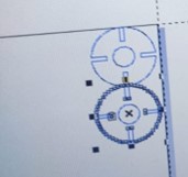
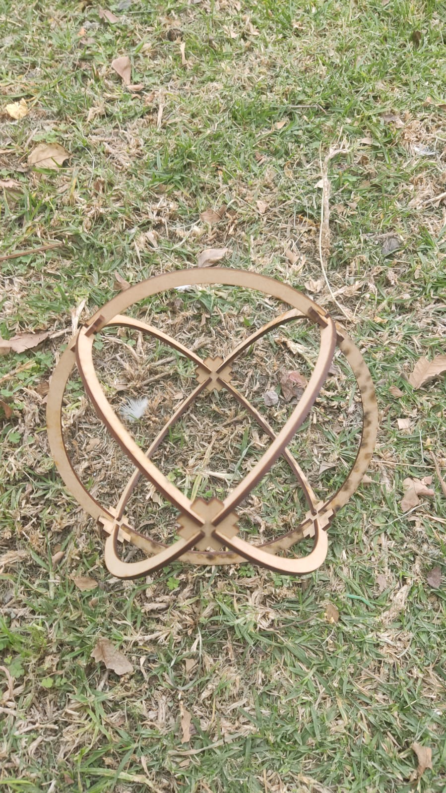
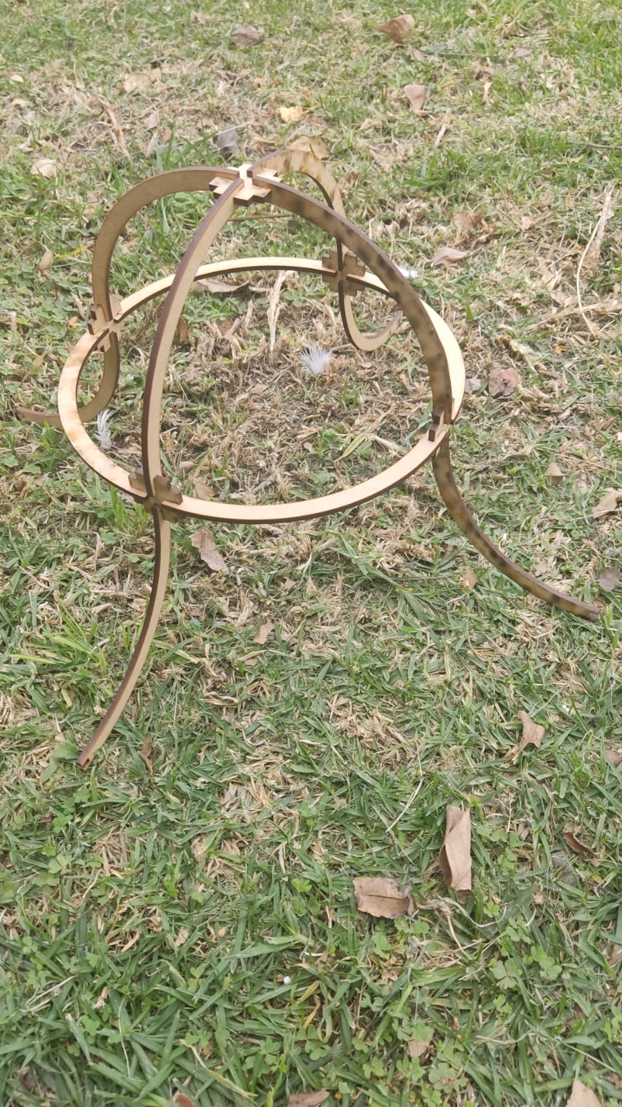
So, after we learned how to do all of that, we can proceed with the shapes I actually made which is this one.
Cutting the shape
Once we have the defined shape, we need to obtain a file with the extension ".dxf" or ".smc". These extensions are needed to use the software of the laser cutting machines. I'll leave a link. for a short drafting tutorial; something relevant that I recommend is to only include the face that you need to cut, without additional letters or titles. Once we have that, we simply save the document with the ".dxf" extension. The software I'm using is called SmartCarve, which is a program based on vector imaging for laser cutting.
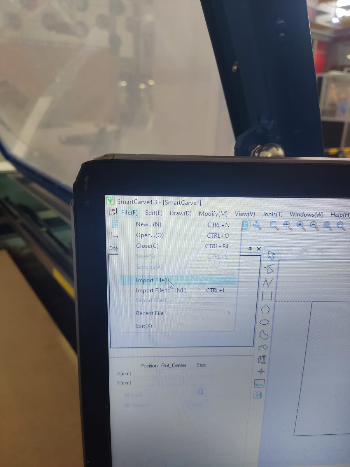
Once we have the application open, we left-click on the file section, click on the option to import a file, and select our file with the necessary extension. Once this is done, the shape we had will be displayed on the cutting canvas.
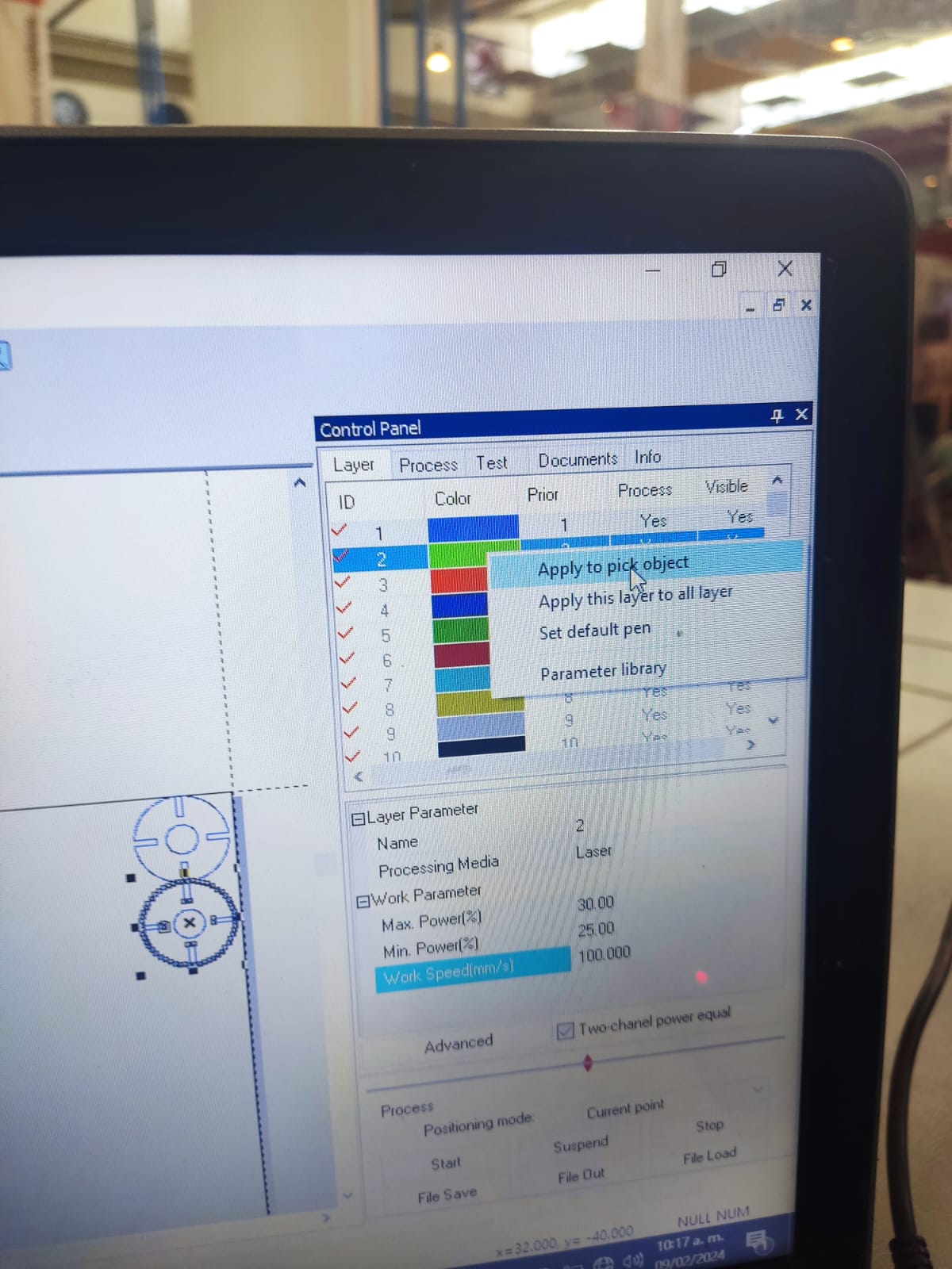
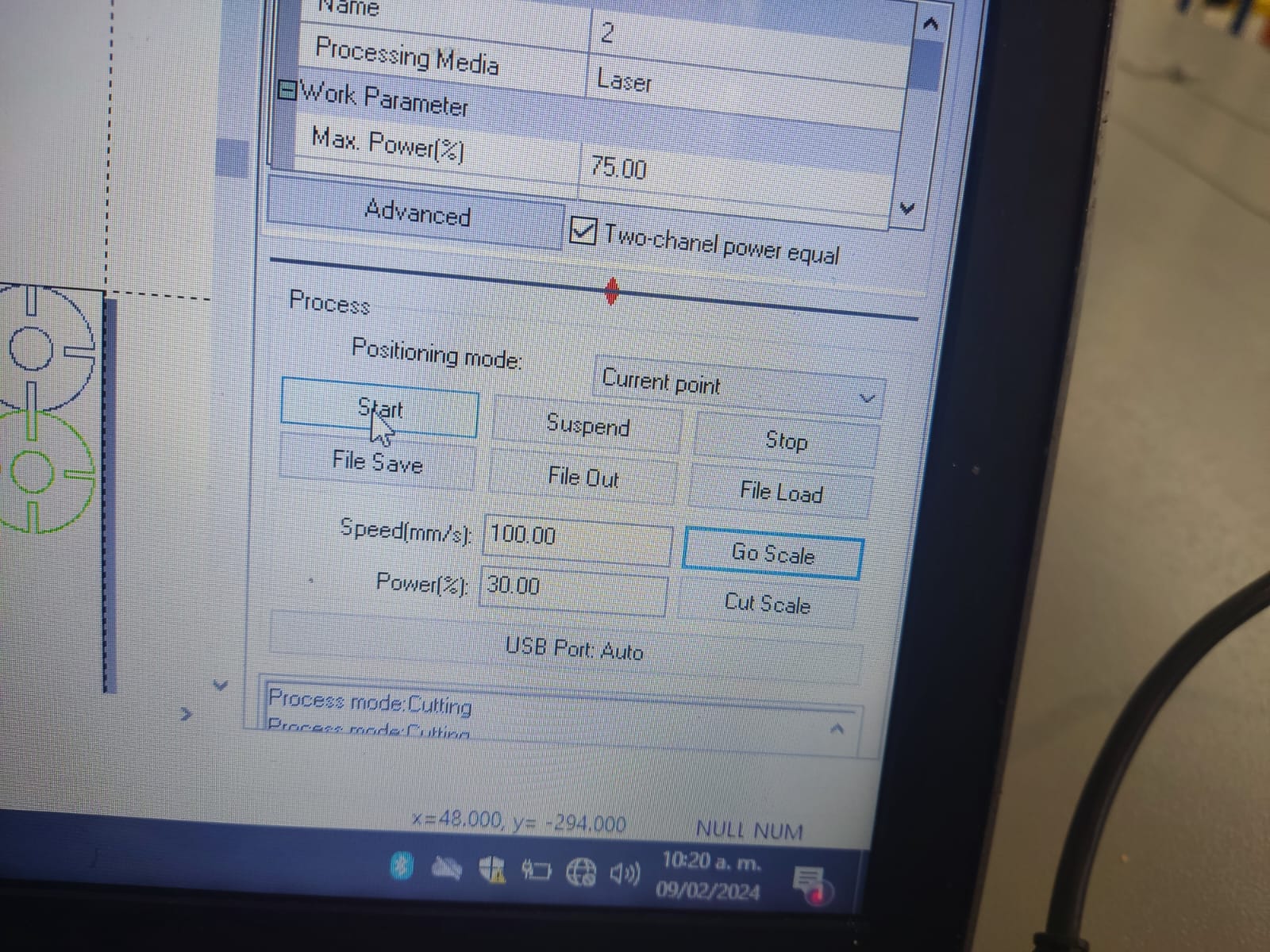
One thing to note is that there are different layers on the canvas that serve different purposes; generally, we will use the first two layers, the blue layer and the green layer. The blue layer is used for cuts, while the green layer is used for engravings. Each layer has different options for configuration, such as cut speed, maximum power, and minimum power. In this section, we need to pay close attention to the data we input, as the quality and depth of the cut will depend on the statistics we have.
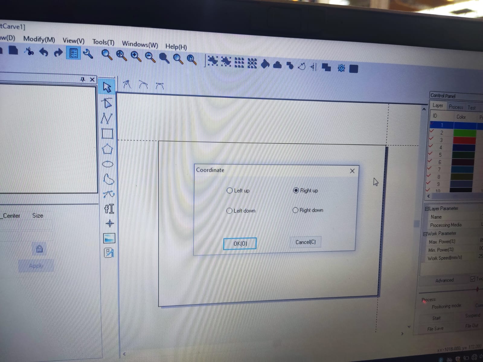
Another thing to pay attention to is the origin point we choose; generally, the program puts it in the upper right corner, so it is advisable to place the laser of the machine we use in the same way. Once the necessary information is inserted, we click on the "Go Scale" command; this command helps to show the cutting scale and the dimensions that will occupy our MDF plate by moving the laser around the cutting perimeter.
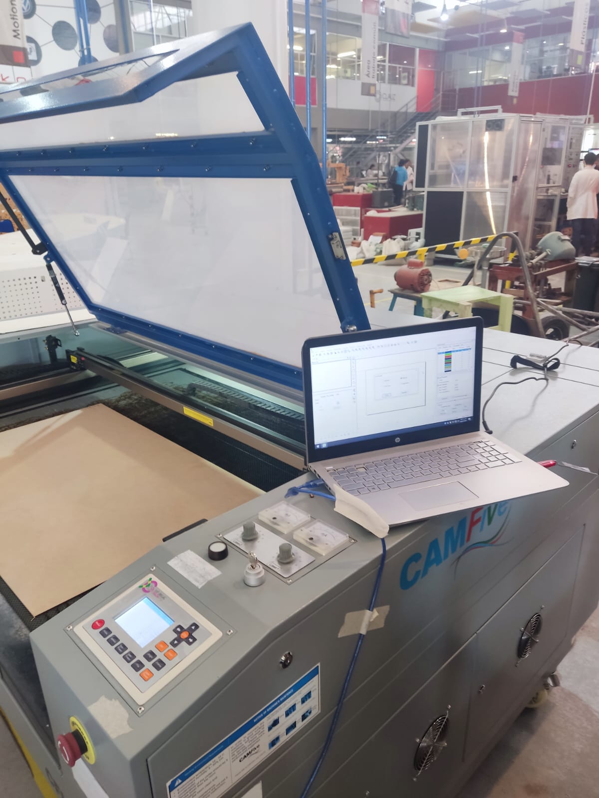
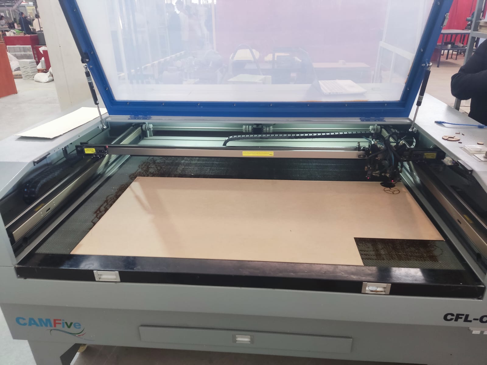
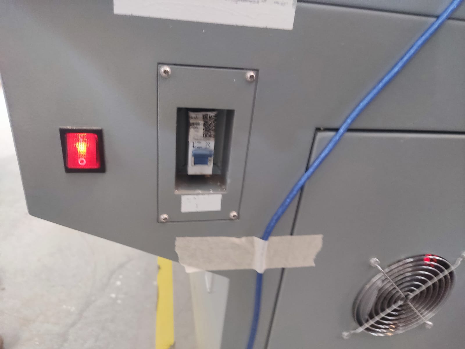
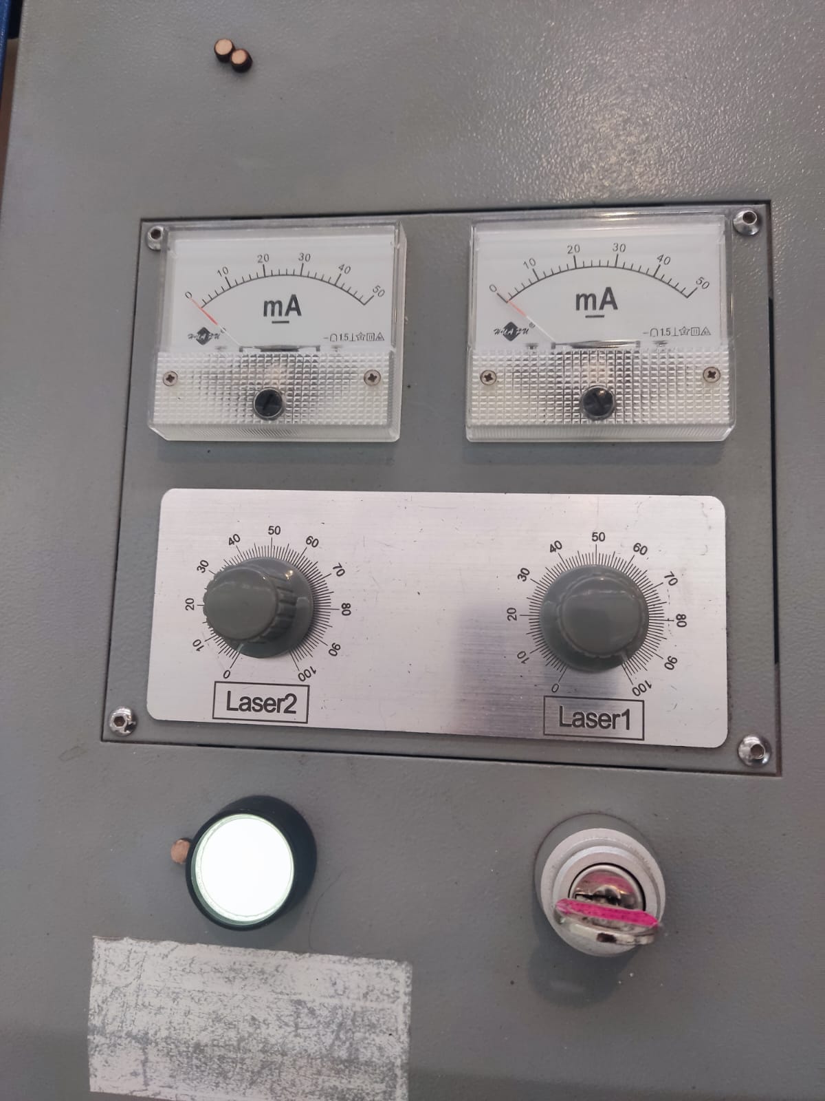
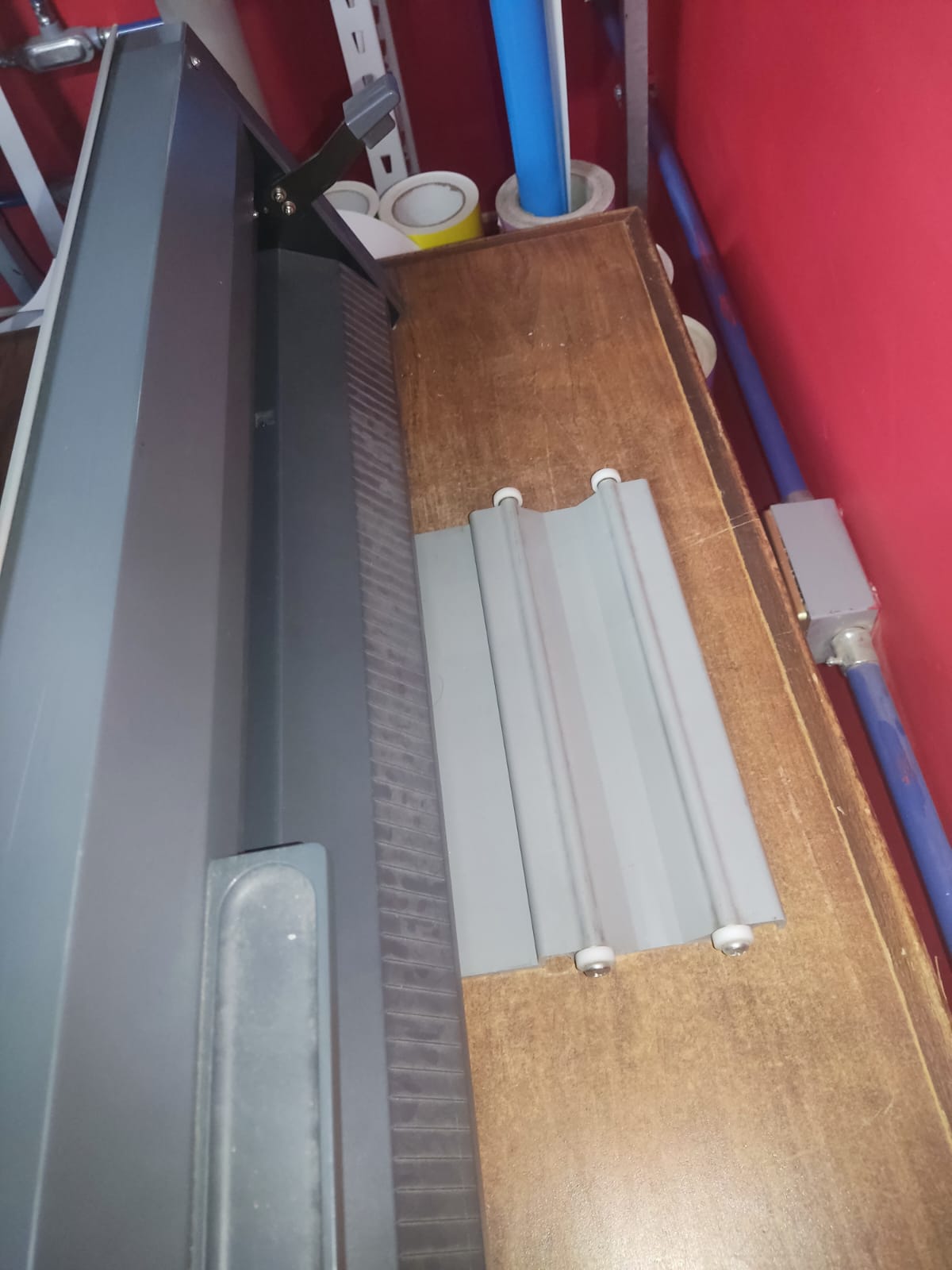
But wait!! I haven't told you yet how to use the machine. The cutter I use is the CFL-CMA1390T, what a tongue-twister! This machine is turned on by first turning on the two rear contacts that allow power supply to the laser machine itself and to the compressor that helps cool the CO2 tubes. After this, we turn on the two switches located on the right side of the machine; once that is done, we insert the key into its corresponding slot and turn it, which should turn on the machine's lighting and its screen. After this, we adjust the power of our laser with the potentiometers on the dashboard and press the white button that allows the laser to be enabled as well as pulling the emergency stop button. Once all these steps have been completed, the machine is turned on and ready to be used.
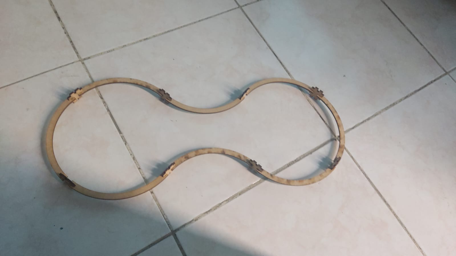
Well, now we have the machine turned on and the program ready to start; all that's left is to press start, and we'll see how the cuts are made in real-time. I'll leave a video that demonstrates some of the cuts, sorry for the bad video quality, but don't worry, I'll get it better next time. Aaaaand that's it! We have our piece.
And this is the final product.
Logos, stickers, you name it!
Setup
Now the vinyl cuttinng, this was a far simpler ordeal than the construction kit, seeing as there are a plethora of options to choose from, my pick was a file that I found from this link.. I tried to save time with a pre-made shape as to focus on designing those rad shapes that I talked about earlier aswell as my final project. So a quick download and cue the road trip to the cutting machine!!
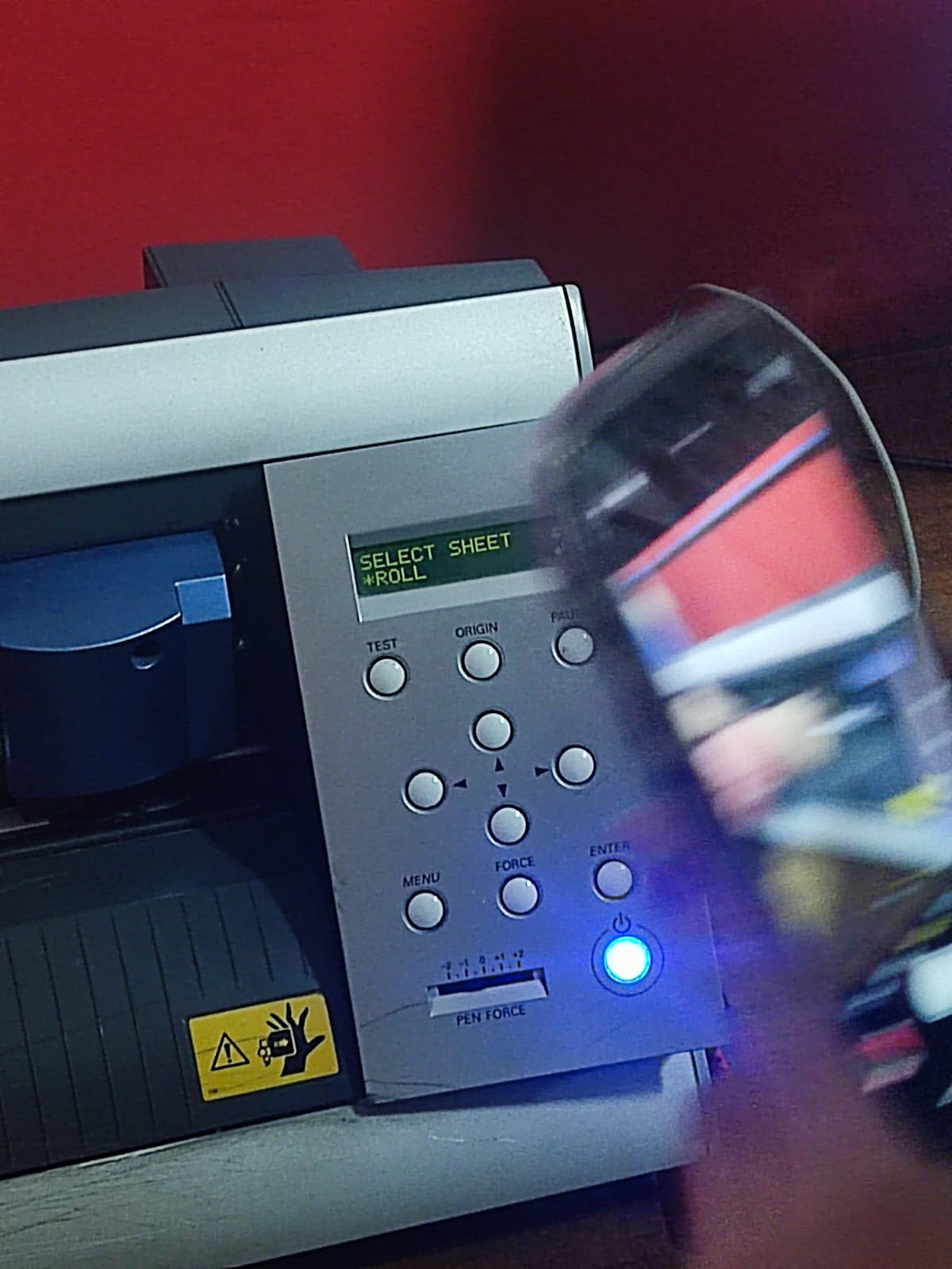
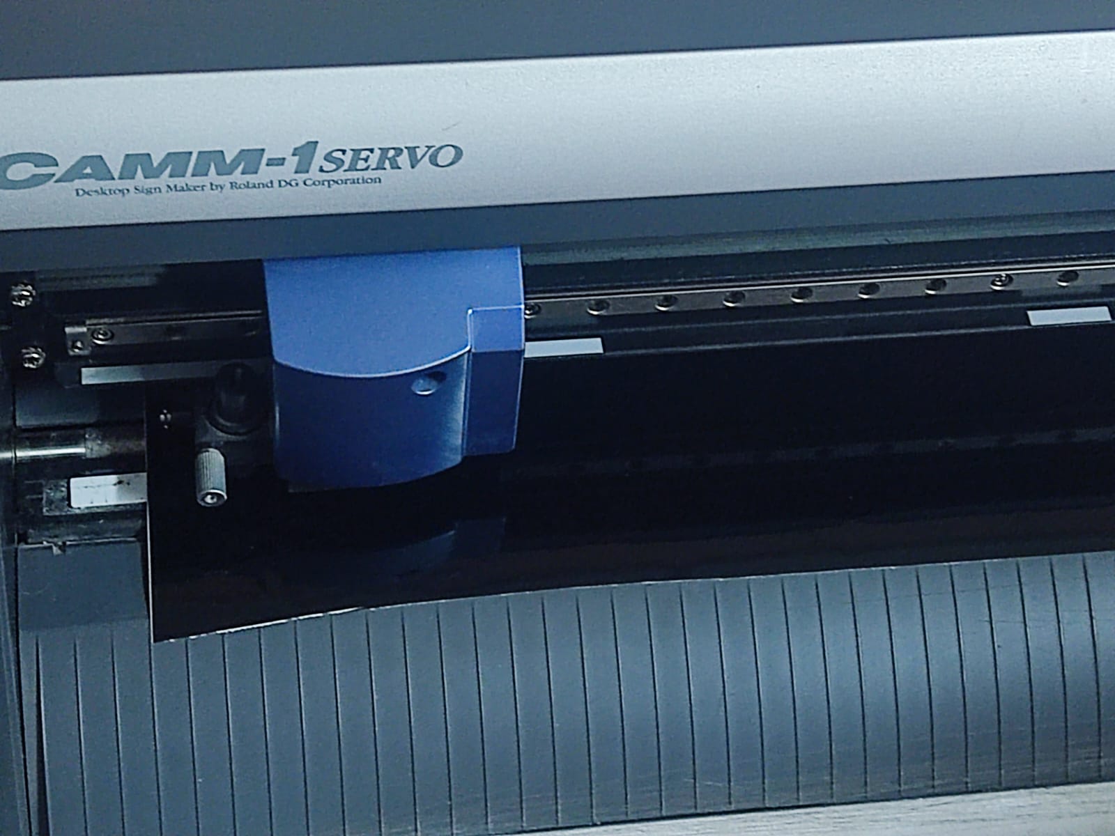
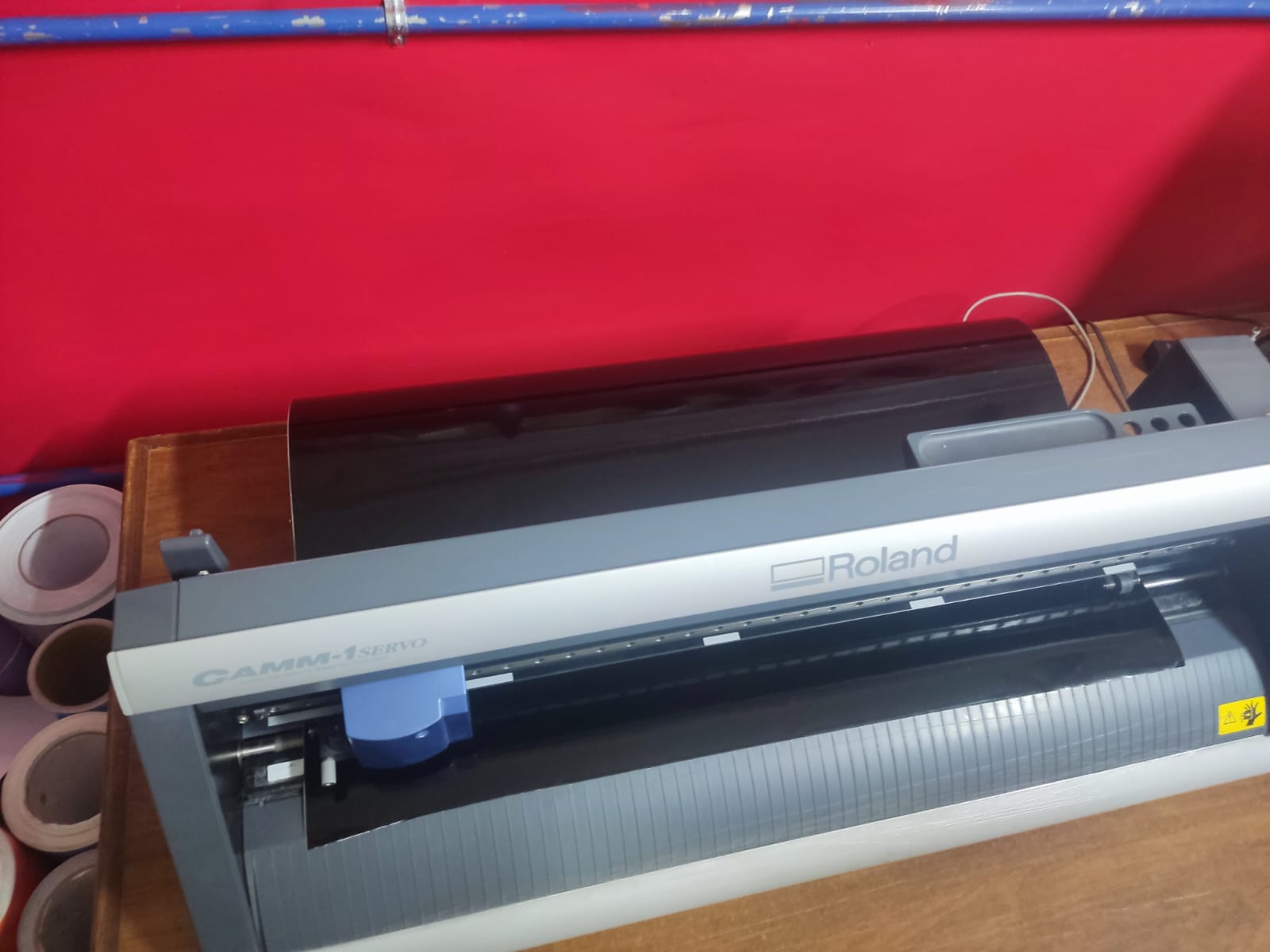
So, in this instance I used a Roland Vinyl Cutting Machine, and the first thing we need to do is load the vinyl roll. This was done by putting it on the platform on the rear of the machine, that place with some tiny wheels on it. Next, we use the lever on the back-left corner to clamp the roll in place. Then, we proceed to turn the machine on, after doing just that we place the servo on the far right end of the work area, by then we ought to pull the clamped vinyl closer to us, leaving it about an inch further from the cutting line.
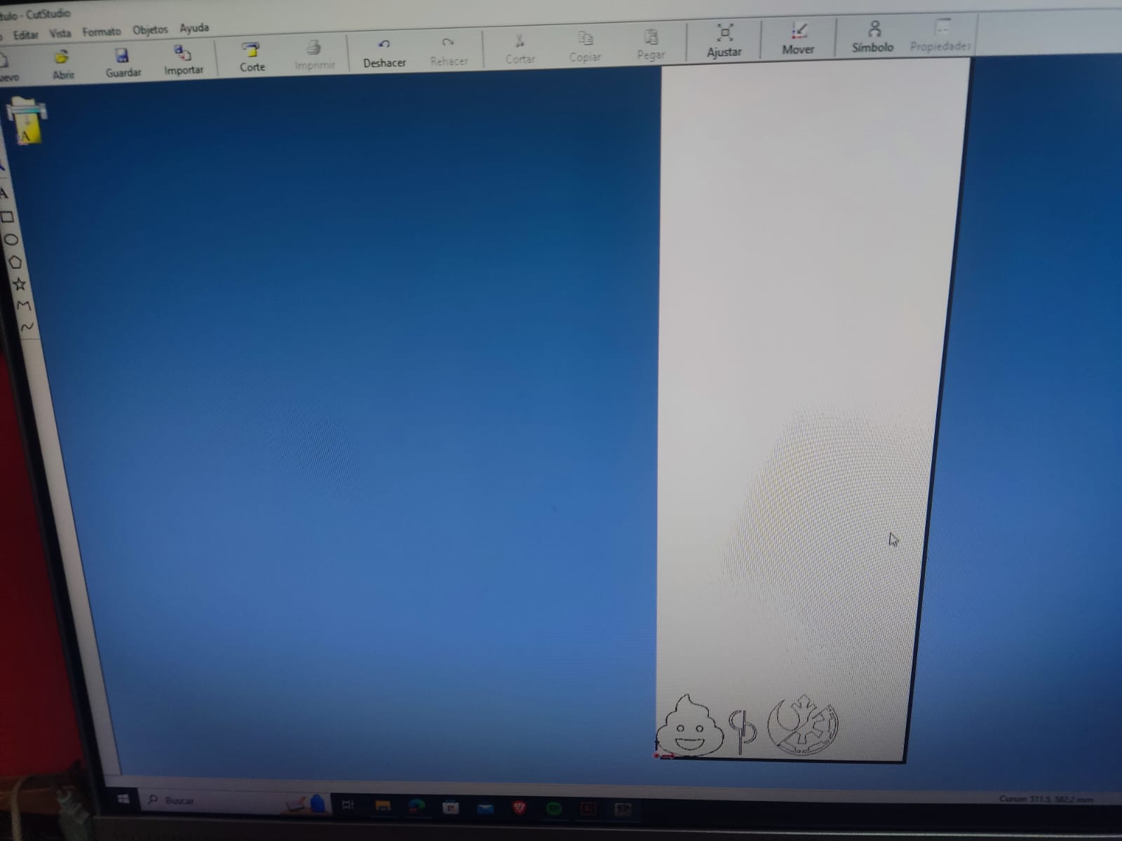
Continuing that process is the import of the files in the software that allows us to get our awesome stickers, in my case I'll be using CutStudio. After importing and placing the files in the work area we press the cut button on the upper-middle section of the screen and let the machine do it's job.
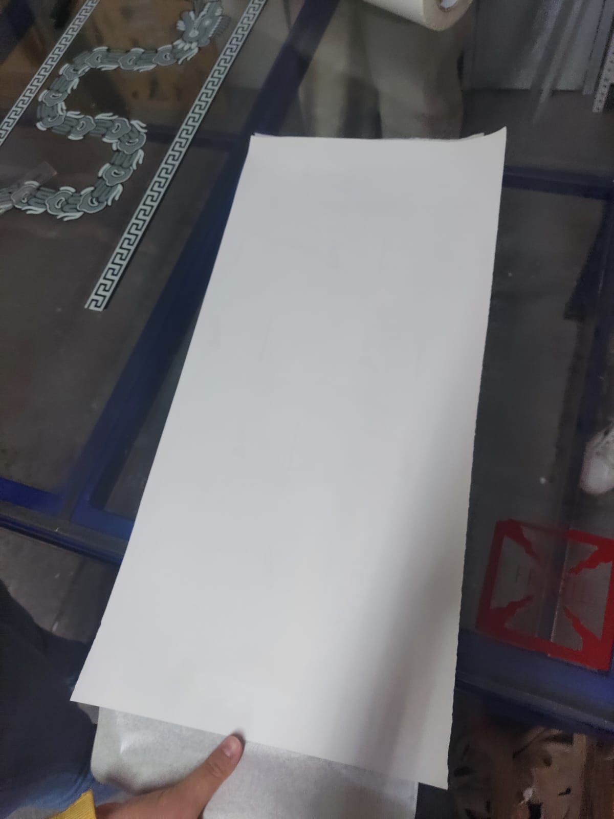
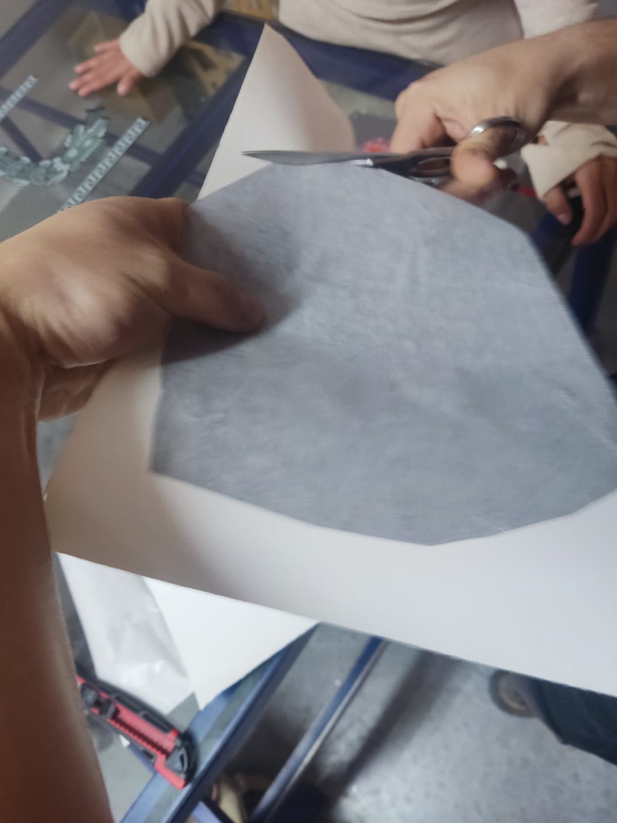
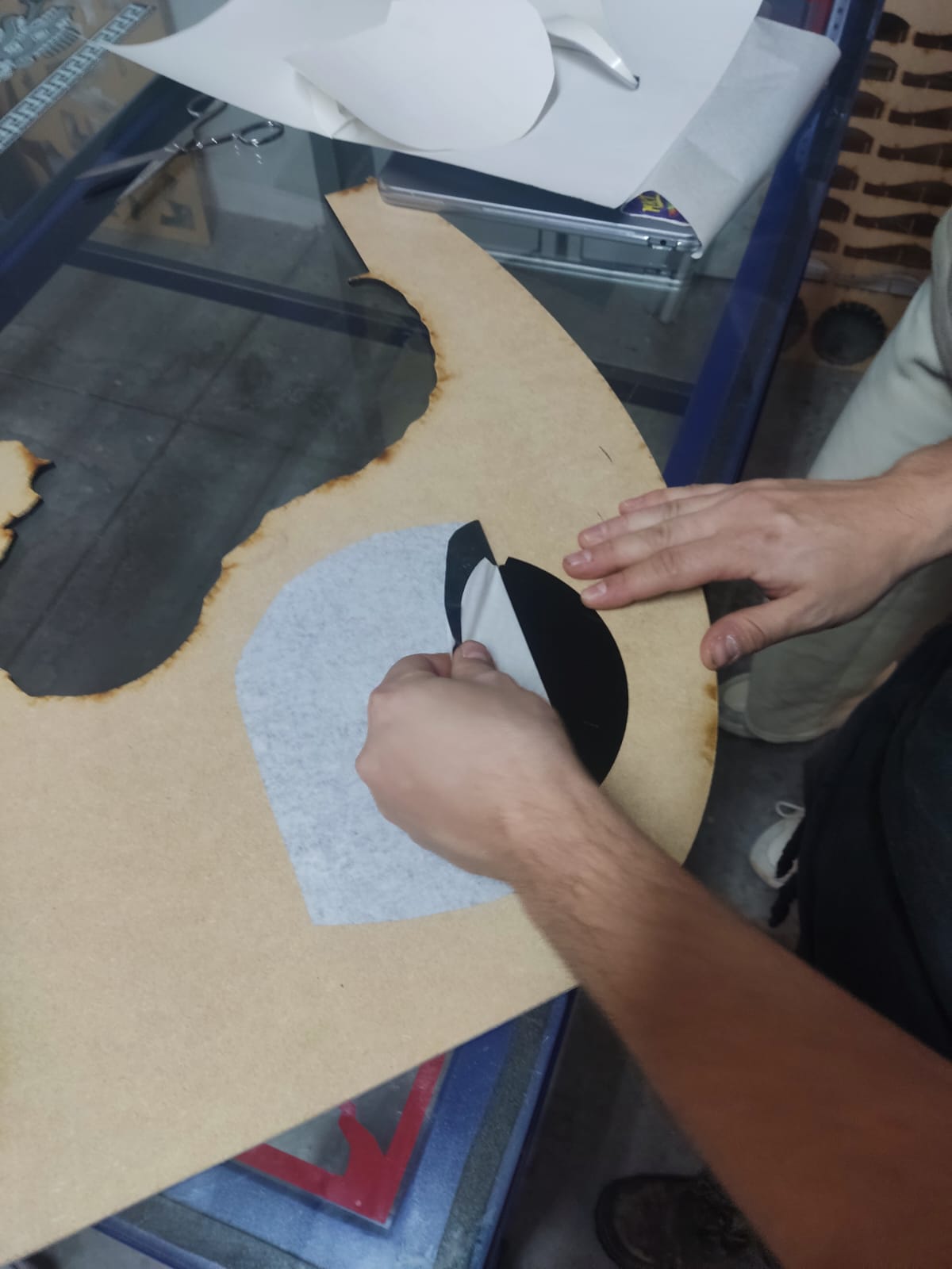
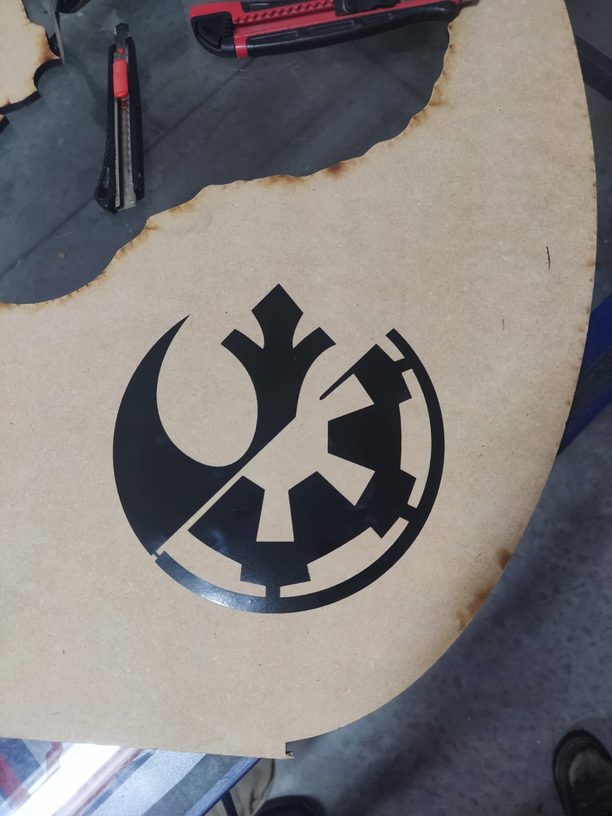
After cutting the desired shape we proceed to use Transfer paper to cover our shape, put it over your vinyl and get rid of those pesky bubbles! After doing that, cut the shape, peel off the back of the vinyl and paste the sticker on the desired surface. Finally, carefully peel off the transfer paper and there ya go! Mine was a Star Wars themed logo, because I absolutely love Star Wars!
So did you liked a bit of that summary/tutorial?
To see what I am blabbering about on greater detail you should visit the Fab Lab Puebla site! after all, that's where I got my summary.