CAD Designs
This week I worked on using 2D and 3D design tools for components regarding my final proyect. You can see the magic grow!
2D Design
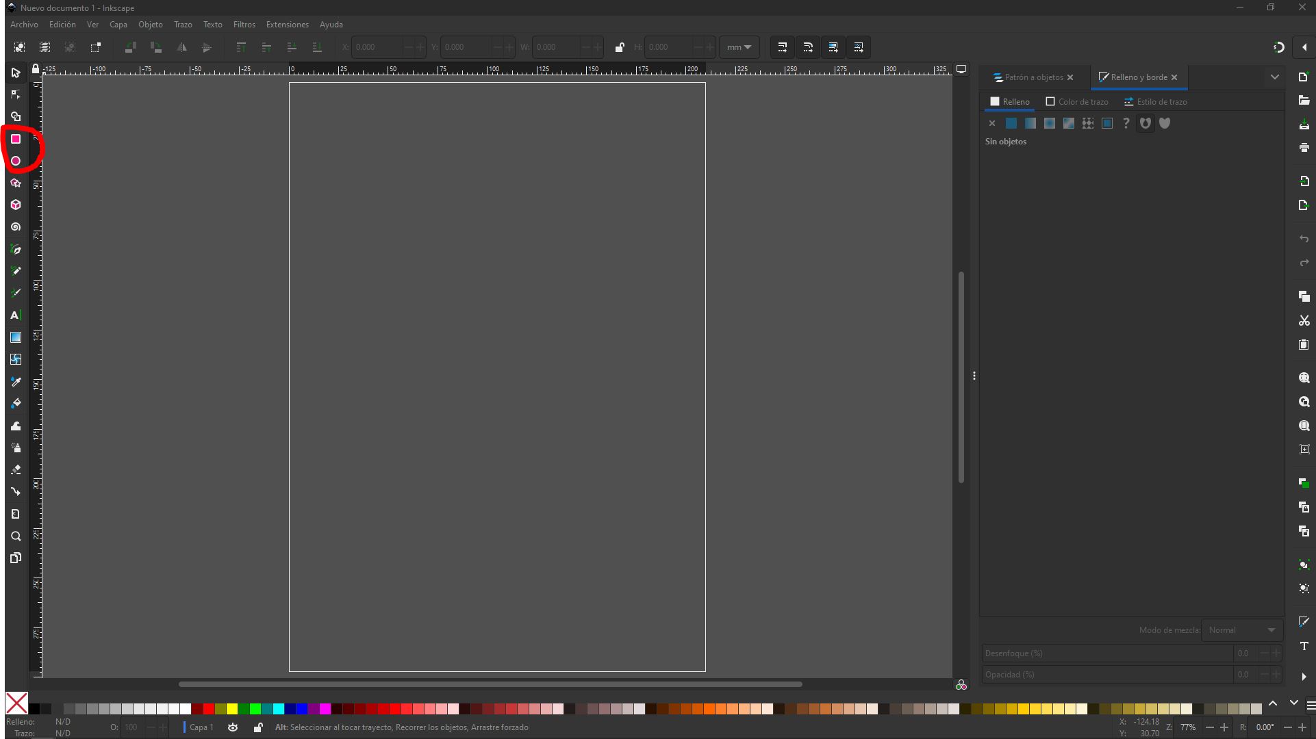
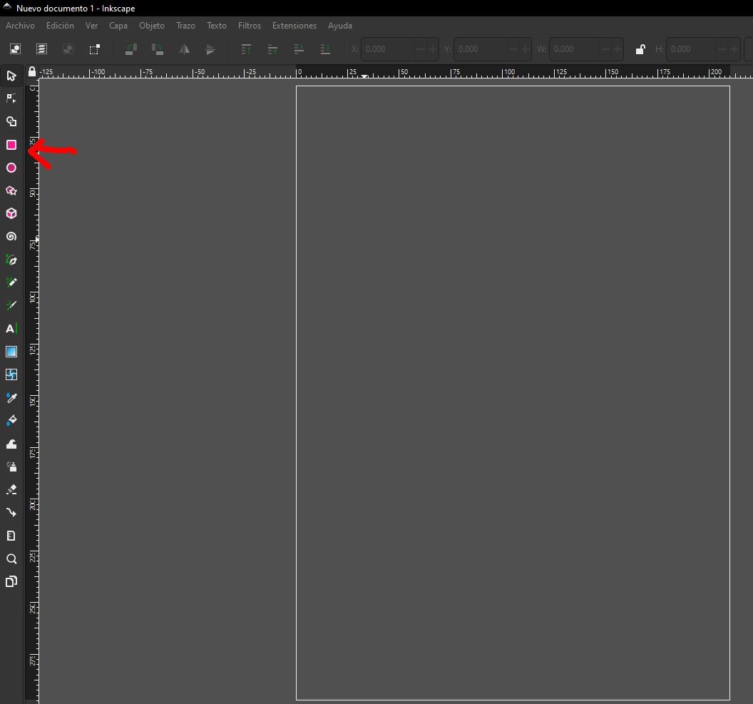
The first step was to identify a 2D design tool. In my case, I used Inkscape, a free 2D development tool that can be downloaded from the internet. If you're interested, I can provide the link.
Once I obtained the software, I used graphic creation tools such as the rectangle tool to draw what would be my system.
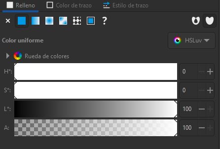
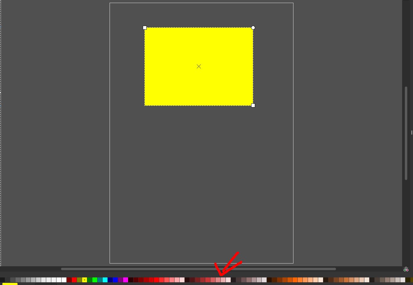
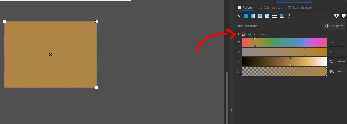
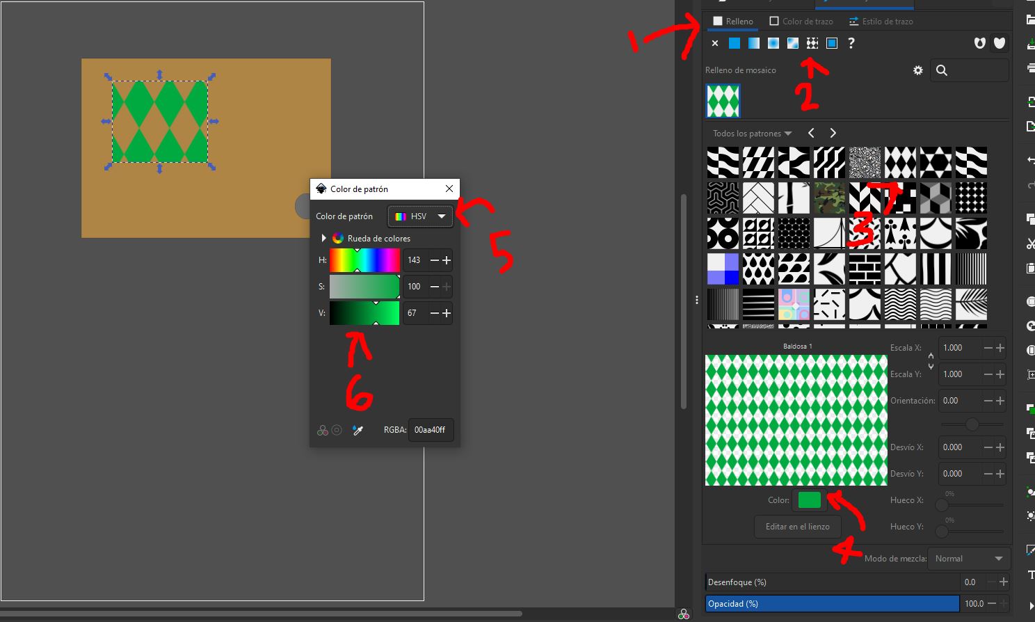
This tool also allows for customization with colors, fill, gradient, and stroke styles.
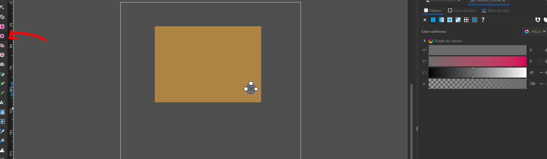
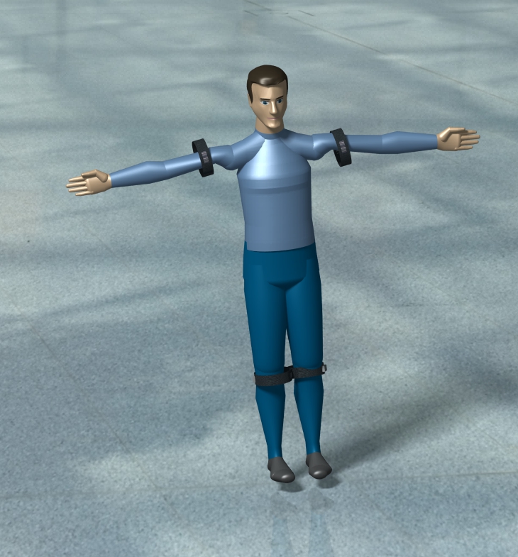
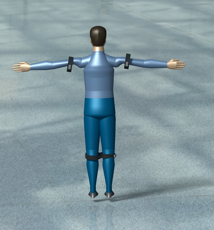
After drawing the rectangles I would use, I moved on to the circles, which would simulate the screws holding the small box containing certain sensors. This box would then be glued to a strip of fabric that would adjust to the width of the wearer's limb and be closed with a Velcro strap.
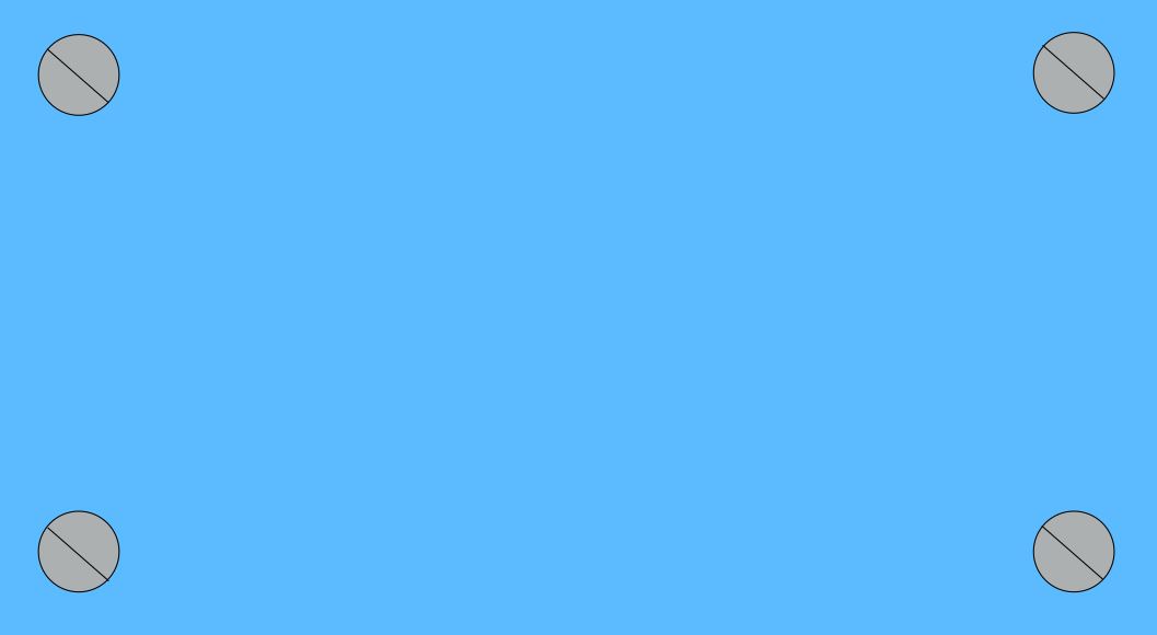
In the end, what we have is a 2D design with both front and back views, showing how the project would look once physically fabricated.

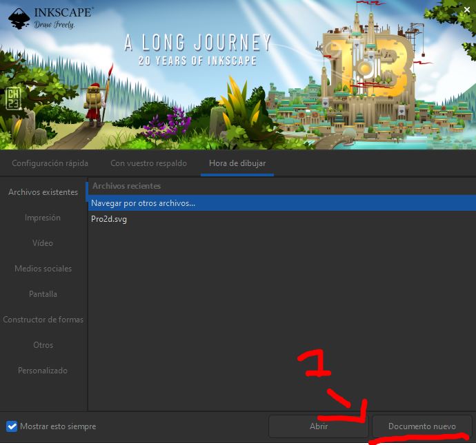
Here's an image sequence detailing a similar process for further understanding:
3D Design
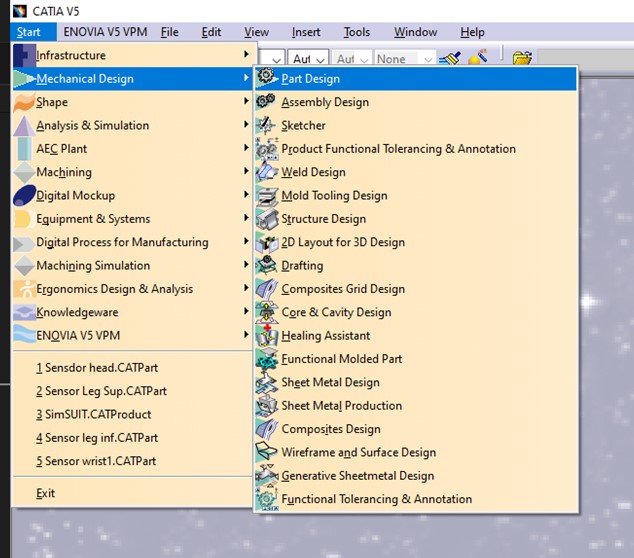
First, let's talk about 3D design, and just like in 2D design, we need to choose a design tool. In my case, I used CATIA, an industrial design tool that allows for 3D designs, 2D industrial drawings, system simulations, and more.
In CATIA, there are different ways to generate documents, but we'll focus on creating what's called a "part". This type of file allows us to create a part, which can then be used in assemblies or simulations.
Our particular part today would be the project itself, and in a simplified manner, this part consists of a small number of circles, two rectangles, and a tool that simulates screw holes.
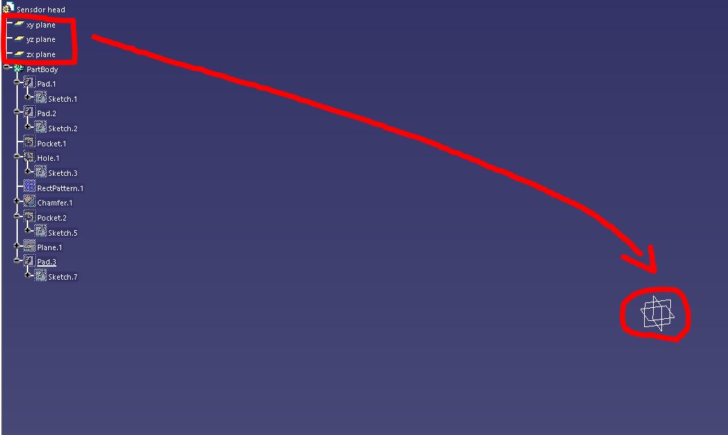
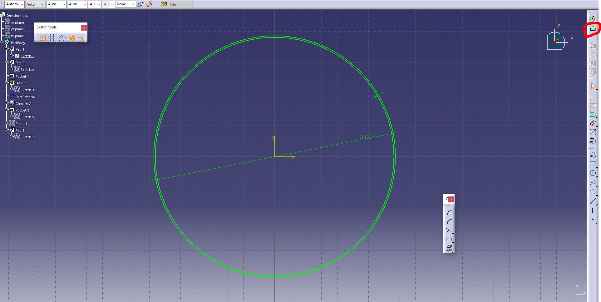
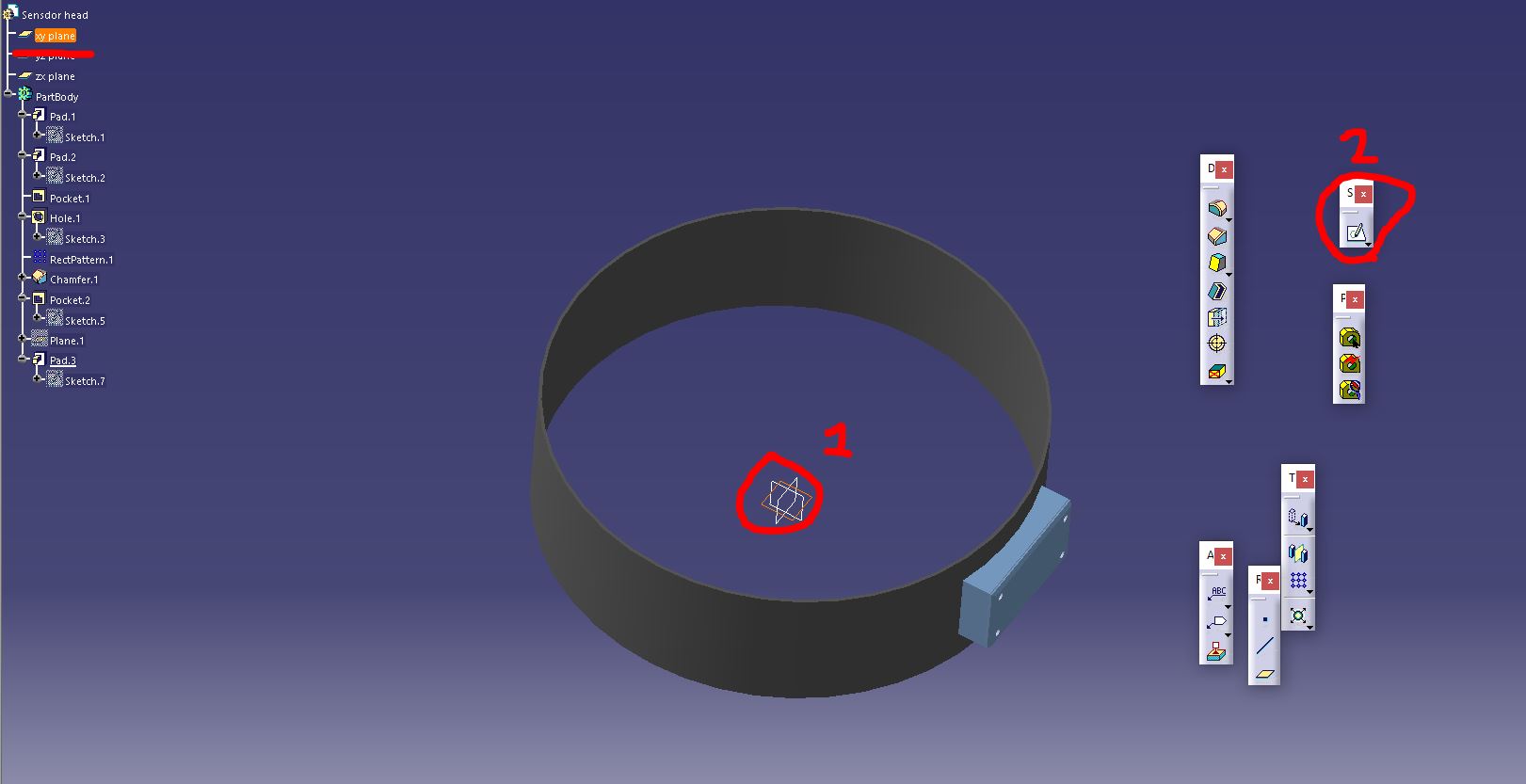
To start our design, we use the Sketch tool, which allows us to sketch on a variety of planes—three to be exact: the "XY" plane, the "YZ" plane, and the "ZX" plane. Depending on the orientation we desire for our drawings, we choose the plane.

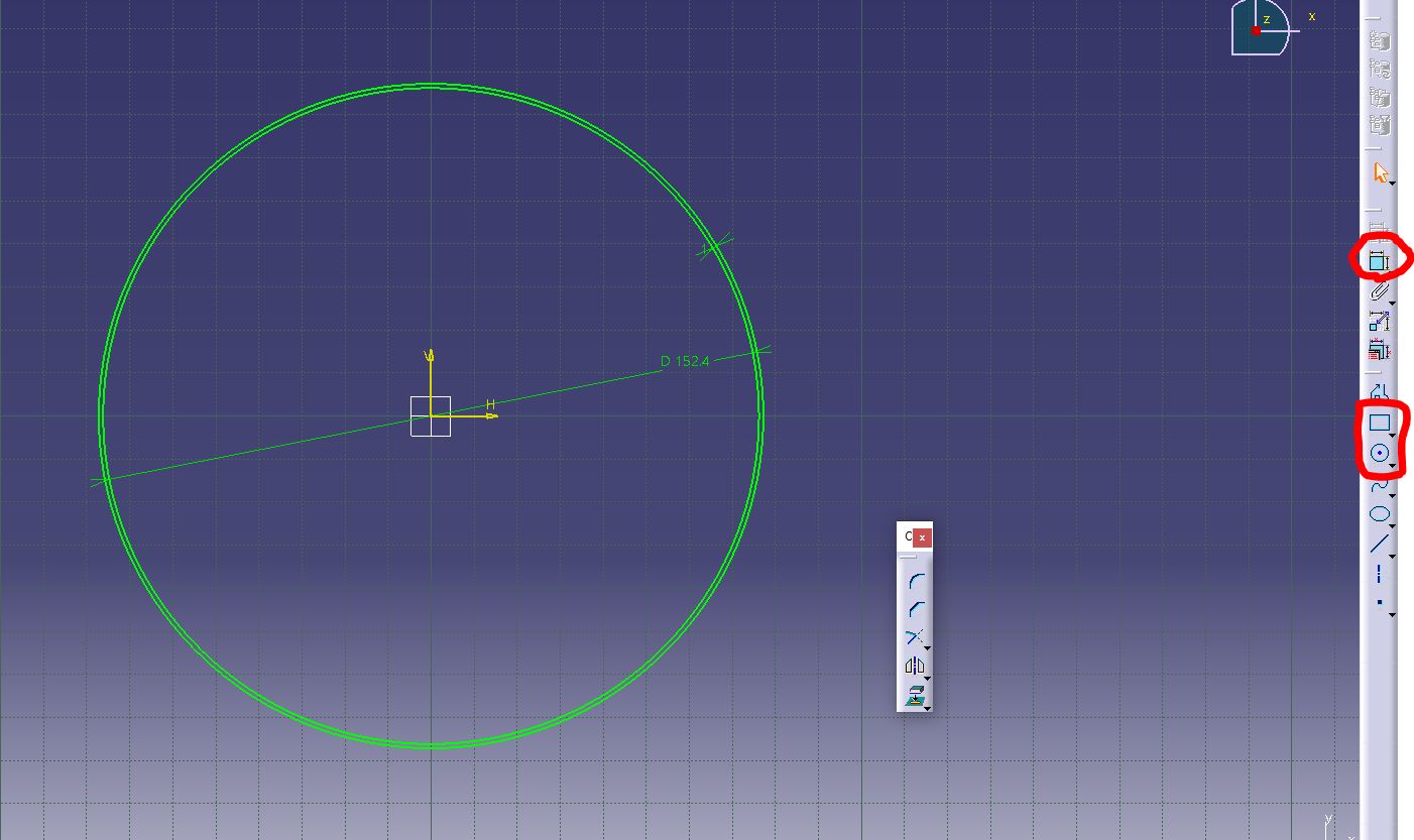
The design continues with the tracing of two circles. These circles need to have a certain distance between them, and fortunately, CATIA has distance constraints that allow us to do this. Once the limits are determined, we establish the diameter of each circumference.
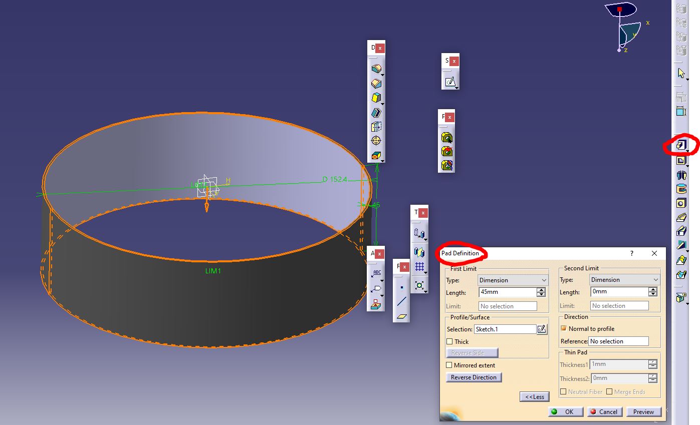
Now, we exit the sketch section and enter the section that allows us to generate fill, create pockets, drill shapes, use chamfer tools, among other things.
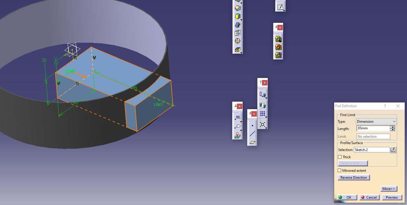
For these circles, we use the Padding tool, which fills the shapes or silhouettes drawn in the sketch. In my particular case, I want my circles to have a total width of 45 mm. Padding has an interesting feature where it allows fills in different directions, such as upwards and downwards, as well as starting the fill from the middle of the shape for equal distribution in both directions. In my case, I just went for one for this.
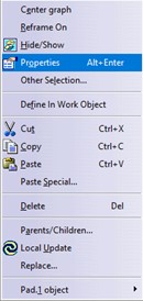
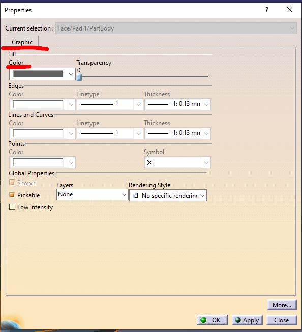
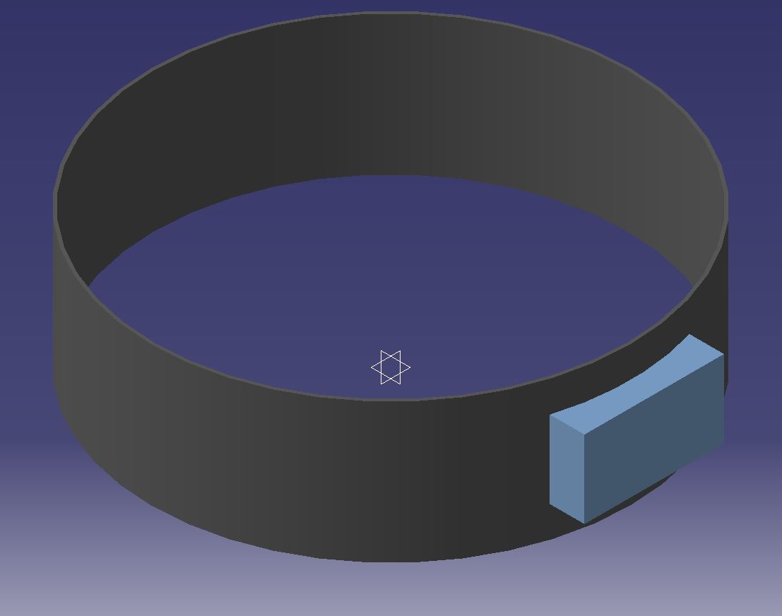
Once that's done, we have a solid circle with the width I desired, but not the color. To change the color, we right-click on the generated body and select the properties option. Within properties, there's a section that allows us to change the graphical options of the body, such as color. Once I've chosen the color I want, my shape looks like this.
But this is just a band without additional components; we still need to add the small box seen in the 2D design. To do this, I select the same plane used for the circles by left-clicking, but if we observe, a new sketch was created within the same body. This allows us to design additional shapes within the same body. We're going to draw the rectangle representing the box. Once drawn, we fill it with the same padding tool, but we'll give it additional fill in only one direction so that it protrudes from the outside of the band we already have.
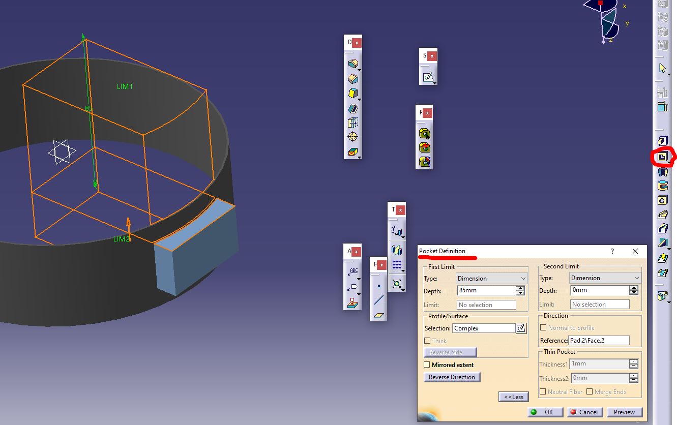
Obviously, this isn't visually appealing, so we'll use the second function found outside the sketch section. Here, we find a tool called Pocket, which allows us to drill shapes into the bodies we have. It's just a matter of selecting the face we would like to alter and the shape to drill into the body, aswell setting the limits of where we want the drilling, either up or down. In this case, I selected the shape within the band and then selected the face below that same shape, indicating to the system that it needs to drill from the upper face of the rectangle to the bottom face, but without drilling the section of the rectangle that's already outside the band.
This leaves us with the shape we have now, and just like in the band, I decided to change its color to distinguish between both components.
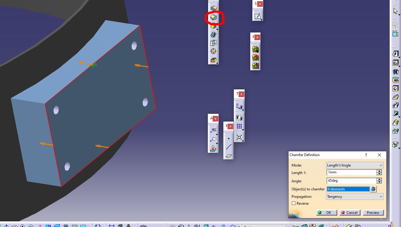
After this, I used another tool found in the same section as the two already mentioned. This one is called Chamfer. This tool allows us to add 45-degree angles to certain silhouettes within the shape, such as corners. All we have to do is click on the tool and select with the left click the silhouettes we want to modify. Once we accept the changes, the shape will look like this.
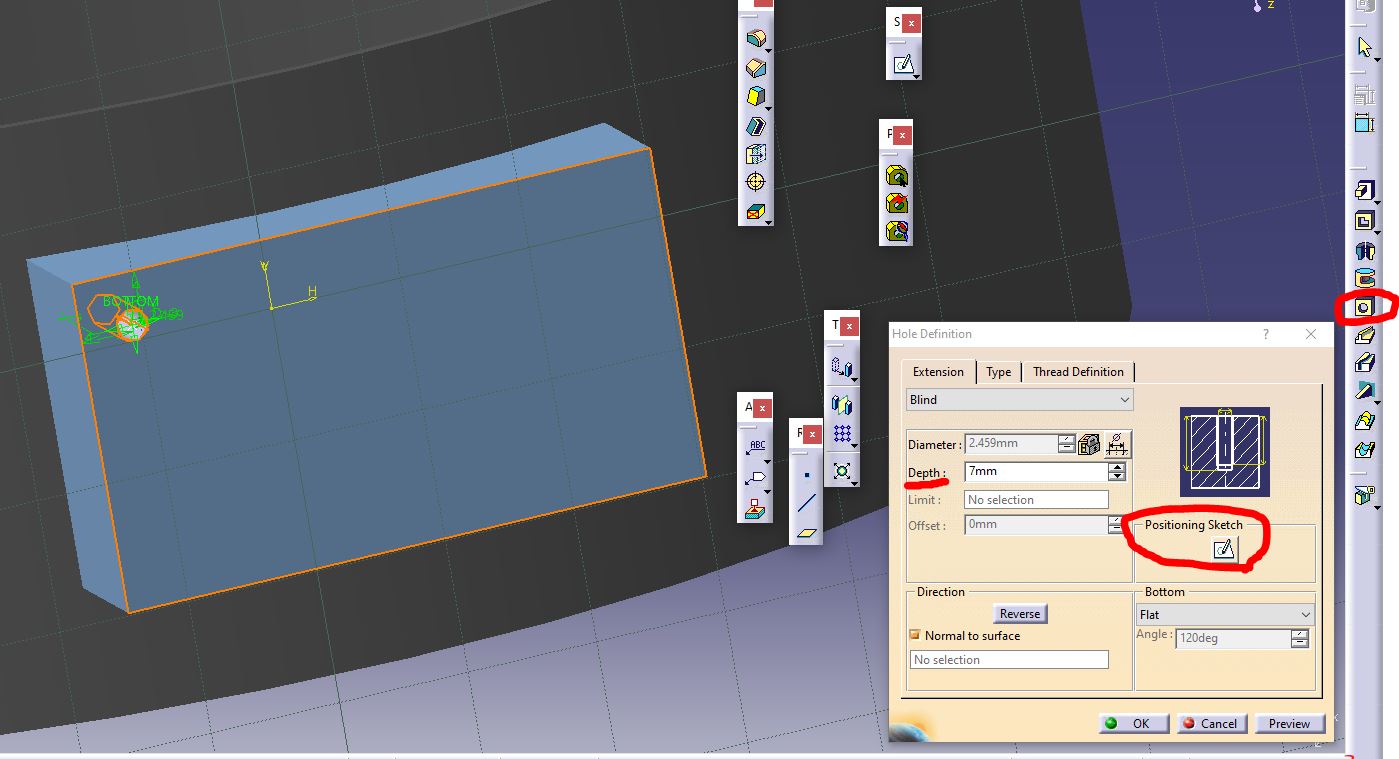
And now onto the last tool to know, called Hole. Just like its name suggests, this feature allows us to create holes in our body. We define the size, depth, drilling style, etc. In my case, I opted for a depth of 7 mm.
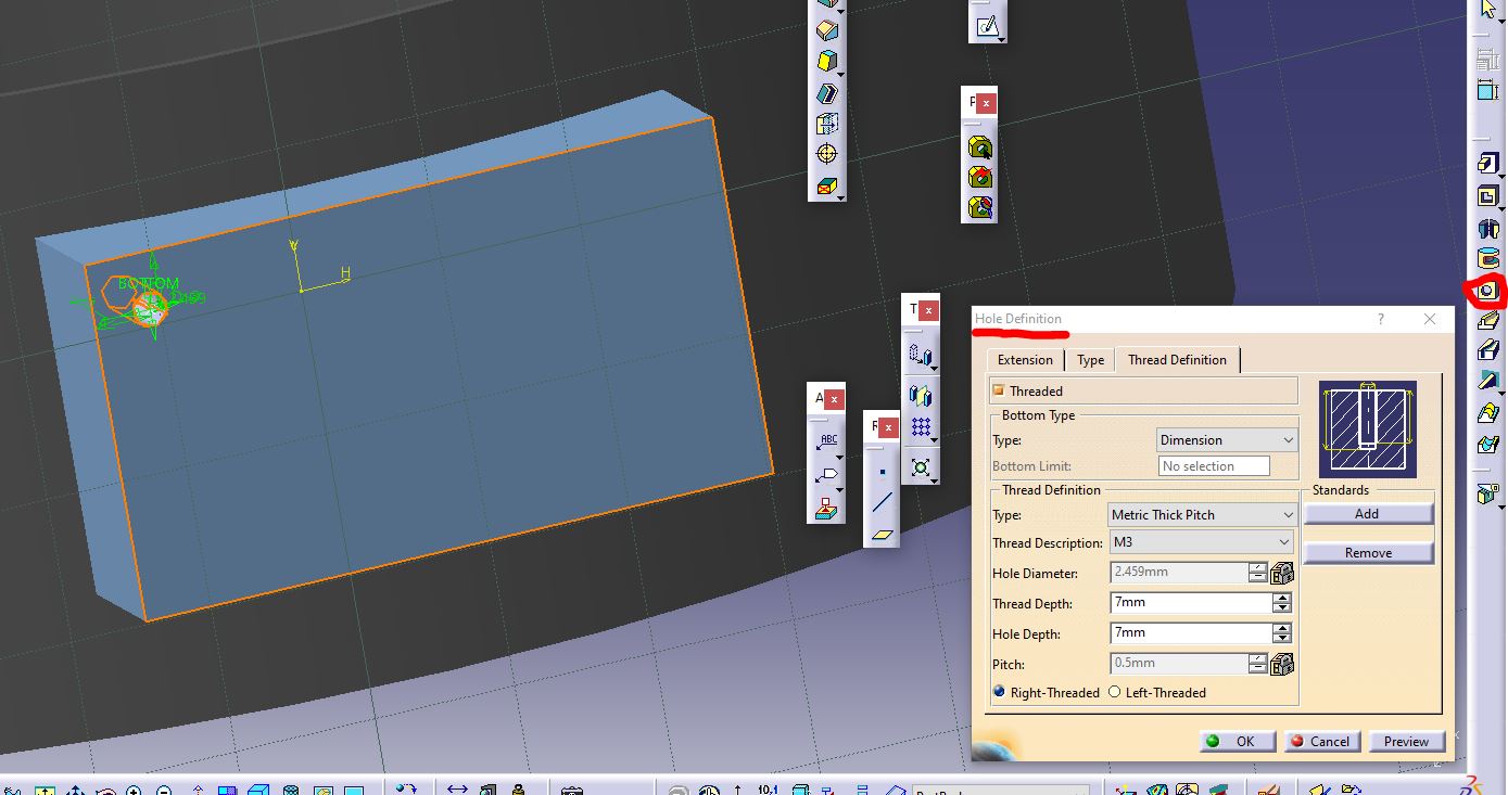
Additionally, I used a feature within Hole that allows for threading with existing metric perforations, such as the one I used, which is the metric M3, referring to M3 screws.
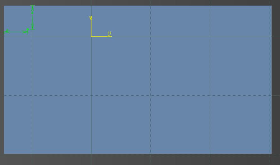
Once the drilling styles we want are defined, we move to the sketch section indicating where the drilling will take place. We left-click and are transported to that sketch, where we can modify the position of the hole in our shape.
We exit the section and can see the drilling already done.
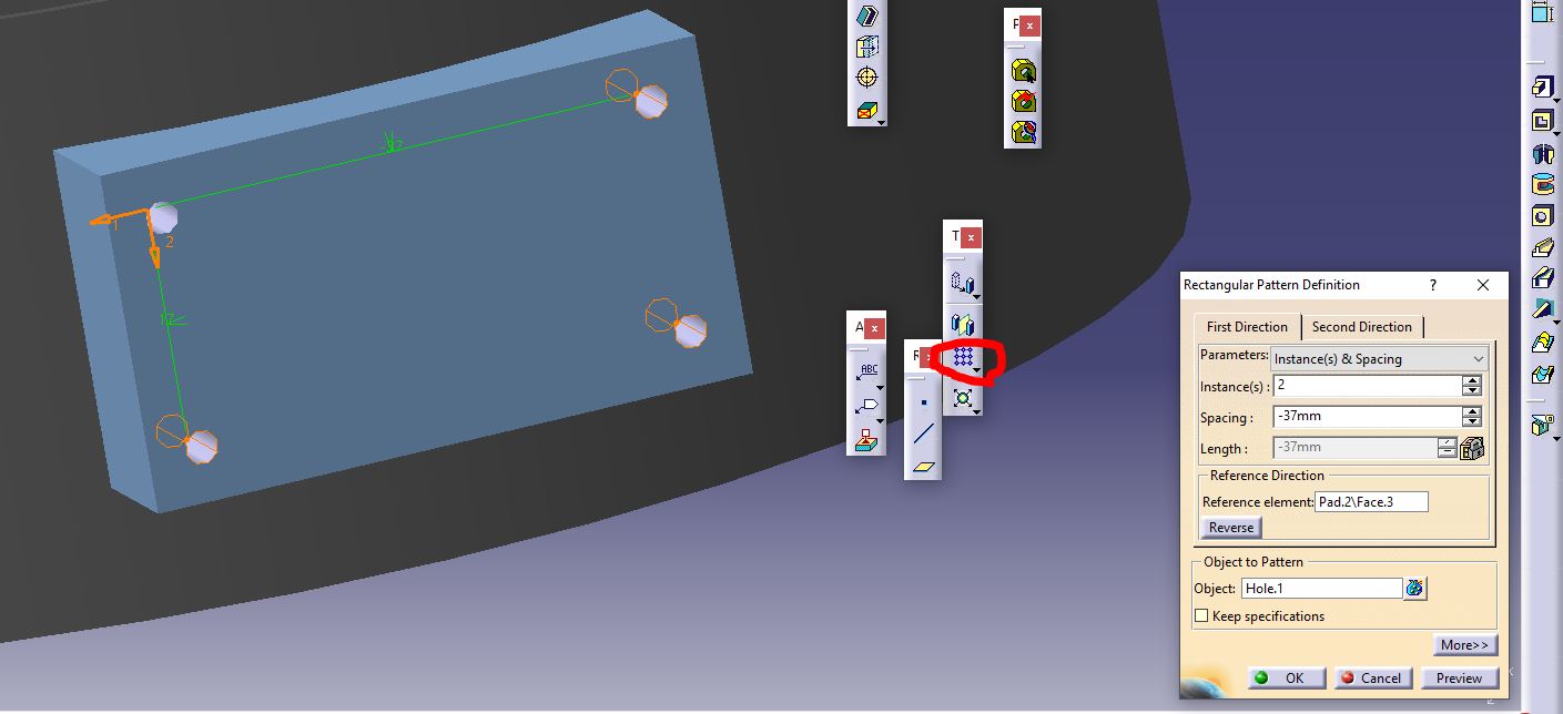
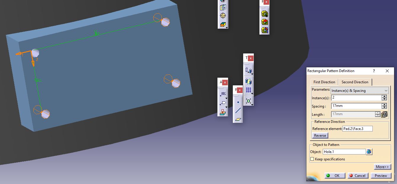
After this, I used another function called rectangular patterns, which allows us to replicate another function in a pattern resembling a rectangular matrix. We define the width and height distances between each instance and the number of instances we want. In my case, I need four to represent the four screws that will be fastened to the container, so I use two instances in width and height. Once we define these characteristics, we accept the changes, and the shape looks like this.
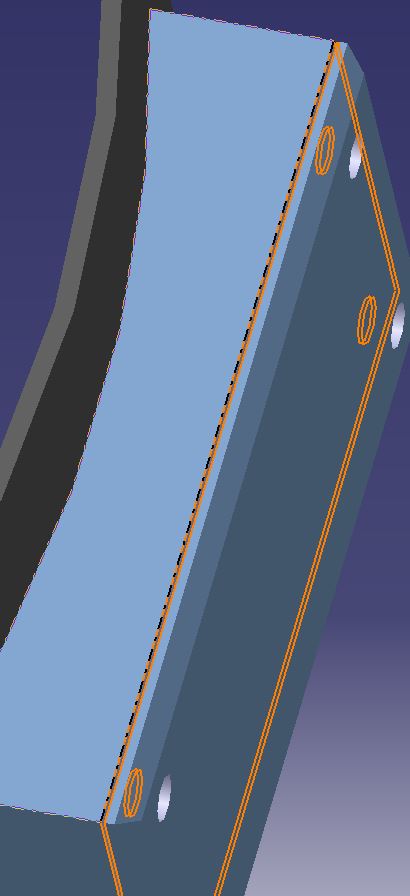
Finally, to add a detail, I used the Pocket function again to create a small separation between what would be the top face of the container, which would be fixed with the screws.
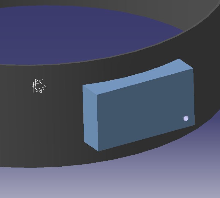
Here's some rendering so you can put it on physical terms.
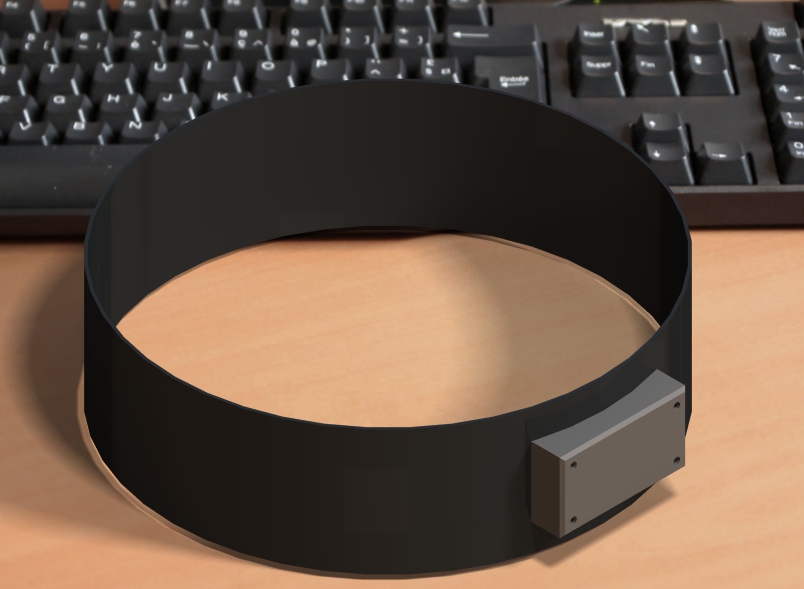
3D Model
"Feast your eyes on this!!" -Jeremy Clarkson