Filament Recycler
All files is here
Video presentation here
Day 1. Problems that have arisen:
Machine parameters Solution:
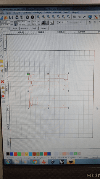
First, we made a comb (without applying tolerances in the RDworks Offset CAM system…) Before cutting out the necessary parts on the laser, we made a test comb to determine the required slot width. The parts were printed with a tolerance of 0.05 mm.

We chose the option that would satisfy us (7.9) for a thickness of 8 mm plywood
Then we applied the tolerances in the CAM system to our models.
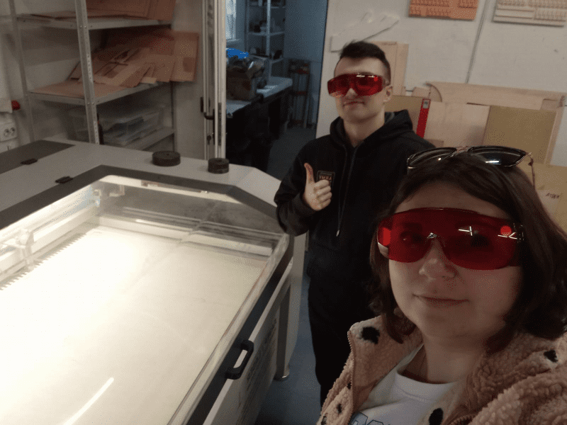
The assembly process:

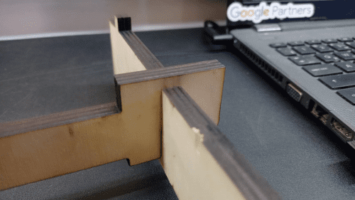
Problem with the assembly.
The grooves do not go down (the front part is longer to make grooves, as on the back of the part)
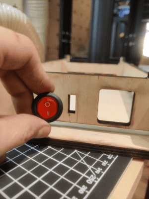
The holes for the ON/OFF button do not match, a 20 mm hole was drilled.

It turned out that there were missing details.
There are not enough holes on the table to mount the bed.
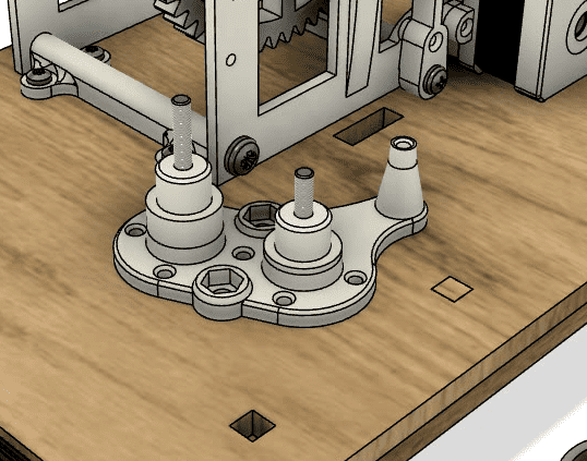
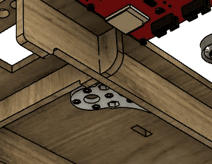
Solution: We came to a common conclusion that we need to first assemble one wall by attaching them to it, and then in the upper left corner with a slight indentation from the edge they can be attached. After watching the video of the complete assembly of the project again, you can also focus on the square hole on the table that is intended for the wires of the stepper motor.
The wiring diagram for the electrical part is missing.

All nuts and bolts are missing.
The screws for the motor mounting are too long for the screwdriver
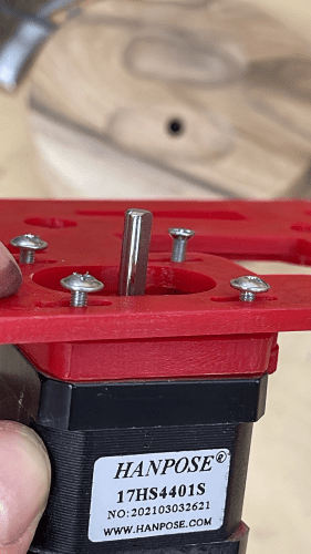
and
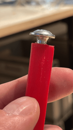
Screws for mounting the motor on M3 16 mm are required.
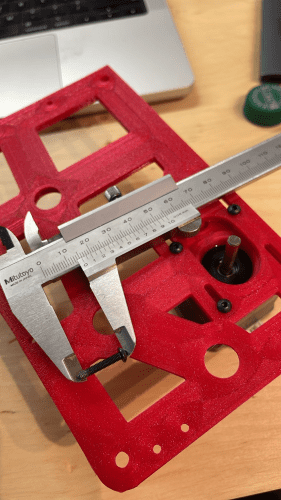
Larger holes are needed here to make it easier to twist.
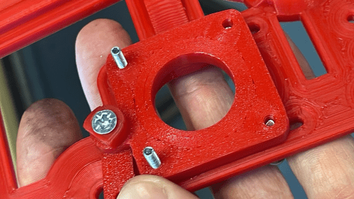
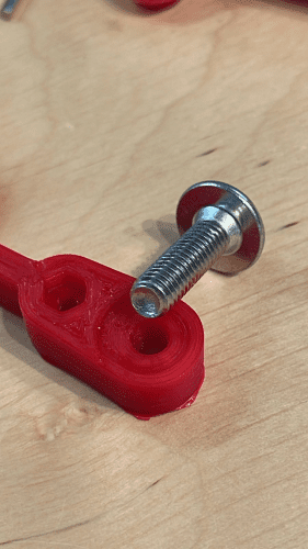
Determine the orientation of the print, because there is a problem with assembly.
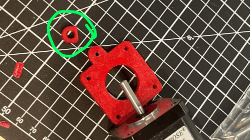
This assembly needs attention - there is no place for the frame mount bolt and the lever needs an additional spacer from the frame.

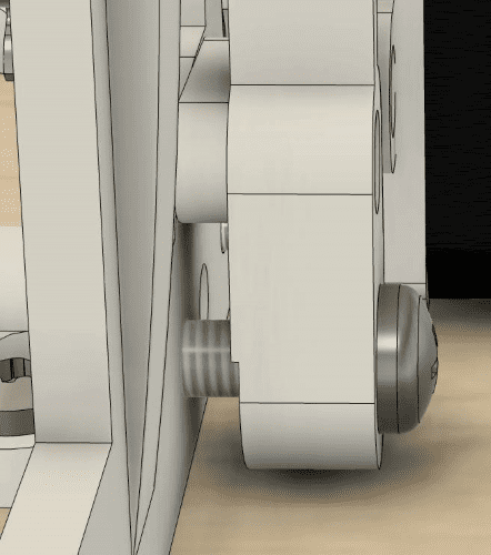
The recessed hole must be on the bar that is screwed to the lever, not on the lever itself. Other parts also have additional spaces for the nut.
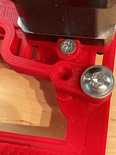
Perfect holes for bearings.
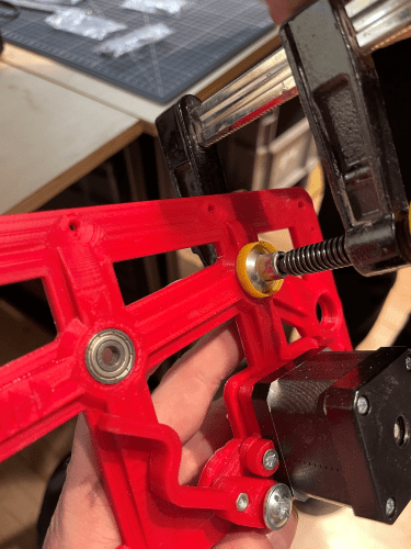
The mechanism works.
Day 2.
We assembled the mechanical part using parts printed on a 3D printer.


holes had to be drilled out as the bolts wouldn't fit through them.


One part had to be trimmed, otherwise, the frame wouldn't come together.
Day 3.
Electronics part
The electrical schematic diagram is shown below.

The connection diagram for the board.


We printed the missing parts and received the electrical connection diagram. We performed a test connection. While attaching the mechanical part to the working surface, I damaged the cover of the work table, so I had to laser-cut it again and replace it.
All mechanical parts were secured. We found the firmware file online, but it turned out to be incompatible. Therefore, we had to perform the firmware update again. To do this, we found the Arduino file and loaded it into the Arduino compiler. It prompted for a missing library. After installing the Uaglib Hall library, compilation was successful. The upload completed successfully, and the program appeared on the screen. The firmware can be downloaded here.
In this system, a Hall sensor is used to measure the number of rotations of the gears that wind the filament. The nozzle temperature is monitored by a thermistor connected to an Arduino, ensuring the optimal temperature for melting the plastic. The motor's rotation is controlled by the Arduino through a driver, and for precision, an encoder is used to track the number of rotations.But we used a ready-made Arduino module.
The program has a built-in interface displayed on the processor's screen. In this program, you can select a specially written G-code with predefined spindle speed and nozzle heating temperature. Alternatively, you can access additional settings and manually adjust these parameters.In the "Motion" menu, we adjust the speed and direction of movement.In the "Temperature" menu, the temperature is adjusted. In the "Configuration" menu, you can select a preloaded G-code.


One part had to be trimmed, otherwise, the frame wouldn't come together.
We tested the robot's operation on the laboratory power source. First, we checked the extruder's heating.
Then we connected the motor and tested the gear rotations. Everything is working correctly. The last step was connecting the power supply unit. The initial startup was successful. The only question that arose was how to secure the filament on the spool for winding. After trying various options, we decided to drill a hole and fix the filament there.

I personally conducted the assembly of the mechanical components, laser-cutting of the main surface, and testing of the blocks' functionality.