.jpg)
.jpg)
Group Assignmen is here
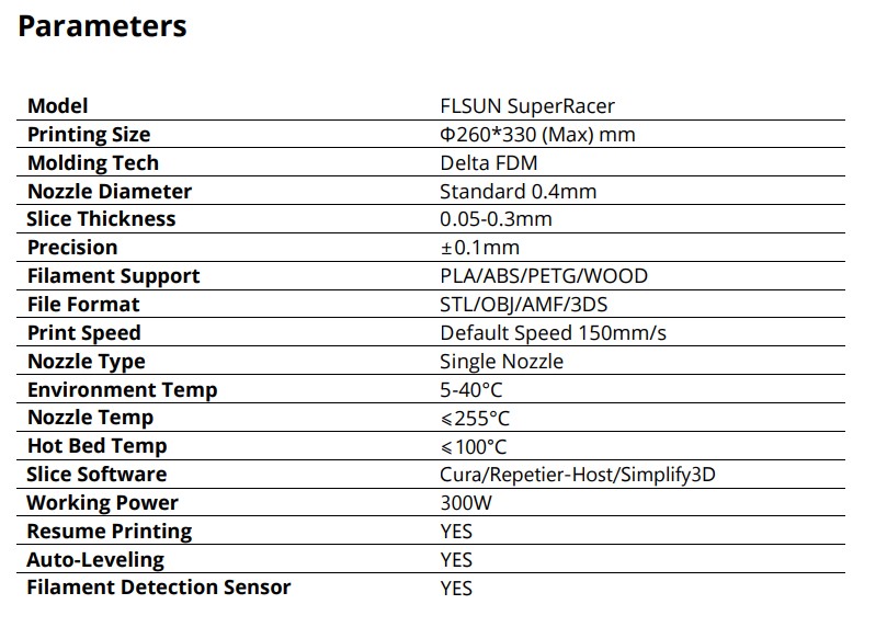
Work with 3d printer
Load Filament

1. Straighten the end of the filament 10cm. Use diagonal pliers to cut the end of the filament into a bevel
2. This is how the filament should look after cutting
3. Push the filament through the PTFE tube in the top shell
4. Push the filament through the filament detection sensor and insert it into the extruder
5. Turn on the power
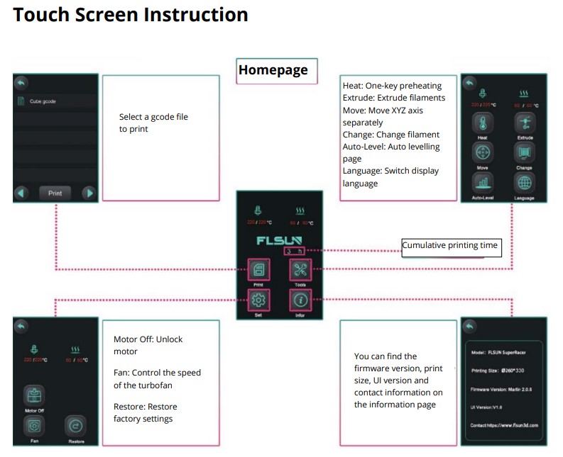
6. Click “Tools” on the homepage
7. Click “Change”
8. Click “Change”
9. If you use PLA please enter 200 and click “OK”
10. Wait for the nozzle to heat up to 200°C, then click “in”
11. Push down the filaments at the same time
12. When the filament is extruded from the nozzle, click “Stop
13. I used CURA as a program for slicing projects
During the first group task, the printer was configured, so we did not have to calibrate it. We started printing right away.
Printing
1. Insert the SD card into the card reader
2. Insert the card reader into the USB port of the computer
3. Double-click to open CURA, then click the folder icon in the upper left corner of the window
4. Select a supported file the CURA supports STL/OBJ/AMF/3DS format files
5. Click on the marked area in the photo to open the slice parameter configuration page
6. Click “Custom” to open more parameter configuration
7. Set the printing height of each layer, SR supports a minimum layer height of 0.05mm.
8. The thickness of the walls in the horizontal direction, this value is divided by the wall line width defines the number of walls.
9. The number of walls when calculated by the wall thickness, this value is rounded to a whole number.
10. The thickness of the top/bottom layers in the print.
11. The thickness of the top layers in the print. 6. The number of the top layers.
12. The thickness of the top layers in the print.
13. The number of the bottom layers.
14. Amount of offset applied to all polygons in each layer. Positive values can compensate for too big holes, negative values can compensate for too small holes.
15. Set fill rate.
16. Set the infill patterns, when the filling density is greater than 20%, the infill pattern should be “Lines”
17. Set the printing height of each layer, SR supports a minimum layer height of 0.05mm.
18. The thickness of the walls in the horizontal direction, this value is divided by the wall line width defines the number of walls.
19. The number of walls when calculated by the wall thickness, this value is rounded to a whole number.
20. The thickness of the top/bottom layers in the print.
21. The thickness of the top layers in the print.
22. The number of the top layers.
23. The thickness of the top layers in the print.
24. The number of the bottom layers.
25. Amount of offset applied to all polygons in each layer. Positive values can compensate for too big holes, negative values can compensate for too small holes.
26. Set fill rate.
27. Set the infill patterns, when the filling density is greater than 20%, the infill pattern should be “Lines”
28. After adjusting to appropriate parameters, click “Slice”
29. Click “Save to Removable driver”
30. Insert the SD card into the printer card reader slot
31. Click “Print”
32. Select the Gcode file and click “Print”
33. Printing will start automatically

A test boat was chosen for the first printing. It was printed in about an hour. There were no errors or problems during printing. all elements are printed clearly and qualitatively.
.jpg)
.jpg)
.jpg)
.jpg)
For the next option, we chose a test layout with thin columns and inclined surfaces. There were problems when printing, Philomen did not stick to the table. When trying to calibrate, the extruder started drawing circles outside the desktop. Additionally, the table was calibrated and the nozzle was cleaned. After these actions, they were able to set up printing. The test part was printed for about 4 hours. All elements of the performance are good, the only drawback is that they forgot to remove the supports when printing the inclined surface. After the test models, they started printing their own models.
.jpg)
.jpg)
.jpg)
.jpg)
Individual assignment
I made the nut and the Christmas tree, since I was able to design these parts myself. For the nut, I simply made a shape and cut a hole of the right size in it.

When designing the Christmas tree, I used the rotation function. First, I projected half the projection of the Christmas tree and then rotated it 360 degrees around the z-axis. this is how the Christmas tree model turned out.


The nut was printed perfectly. The first time I tried to print the tree, I forgot to turn off support again, so part of my tree was printed in the middle of the cylinder. After receiving support, the Christmas tree went to print. From above, the figure turned out very well, but if you look from below, you can see a bit of webbing from the plastic, since these are all protruding surfaces. In general, working with a 3D printer was a pleasure.
.jpg)
.jpg)
.jpg)
.jpg)
With the help of 3d printing, it is possible to produce more complex parts that are impossible or very difficult to produce using subactive methods. If with 3d printing, you can make parts porous or with holes along the horizontal axis, which is difficult to do, for example, with CNC milling. Also, 3D printing creates parts in one piece and does not need to be divided into parts, if it is some kind of complex cutting.
The nut can be made using a router, as it is a very simple element. But it is practically impossible to make a Christmas tree with the help of milling. After all, the milling cutter can only cut from above. Therefore, there will be no deepening under the branches. If you put the Christmas tree model horizontally, you can cut out only half of it.
For 3D scanning, the Revopoint Pop2 scanner was used.
1. Unpack. The set includes a scanner, a stand and a rotating platform.
2. Connect the scanner to the rack. Connect to the computer with a cable.
3. Install the Revo scan 5 special software on the laptop.
4. The interface is immediately visible to the scanner (no problems occurred)
5. It is necessary to place the scanning object on the rotating surface
6. For the first time, it was a standard white figure.
.jpg)
.jpg)
.jpg)
.jpg)
Pay attention to the distance during setup. On the panel's right side, there's a scale from too far to too close. Object centering is in the bottom left corner. If the distance is too large, quality decreases; if too close, the object may not be fully scanned.
After scanning, unify all points and adjust the model. This takes some time.
Objects retain their actual dimensions during scanning, which is convenient for modeling large spaces, given the time-consuming measurements.
Scanned various objects: a white gypsum figurine, a red apple, a colored anime character figurine with many details, and a white horse with a colored print.
No issues with scanning the gypsum figurine, except for the need to scan shaded areas (nooks, behind the ears) for greater detail.
.jpg)
.jpg)
Scanning the apple was easy and successful, capturing both color and shape.
.jpg)
.jpg)
Scanning the anime character figurine was less successful due to many hidden areas.
.jpg)
.jpg)
Scanning the horse became interesting, as the scanner perceived colored areas with a logo as openings.
.jpg)