The activity carried out this week consisted of:
We take care of measuring the energy consumption of an output device.
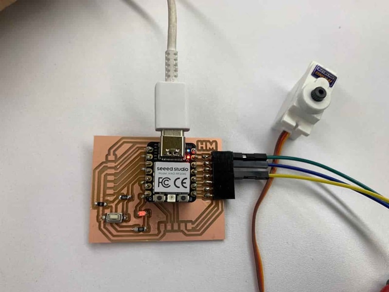
We incorporated an output device into a microcontroller board we had designed, then programmed it to perform a specific action.
Within the framework of our academic activities, we hold both in-person and virtual group meetings to advance our collaborative project.
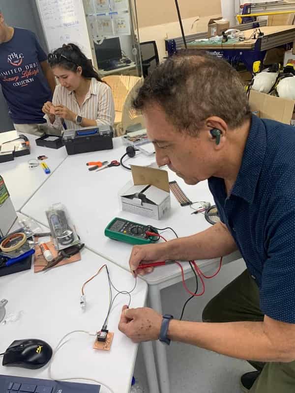
We gathered at the FAB LAB UCSUR on Saturday, where we took advantage of the space to work as a team and address any questions that arose. In addition, we participated in OPEN GLOBAL TIME, an initiative that allowed us to connect with other groups and share knowledge.

The next day, we met virtually with colleagues located outside of Lima to strengthen collaboration and achieve our group goals.
During these interactions, we received support and guidance from our colleagues, including Adrian, Rico, and others, who provided us with assistance in resolving our concerns.
These activities not only contributed to the progress of our project, but also demonstrated our commitment to supporting the FAB LAB academic community and fostering peer-to-peer collaboration.
Each of us also received specific tasks to carry out individually, which will allow us to advance our work in a more efficient and coordinated manner.
For this group project, we decided to carry out individual measurements using the dashboards developed during the previous week. The objective was to acquire skills in measuring amperes and volts, replicating the process on each board.
Using a multimeter, we measure the voltages on an OLED. To perform this measurement, we place the COM terminal of the multimeter on the GND and the mA terminal on the 3.3V point of the OLED. Below, we present the results obtained when making this connection.

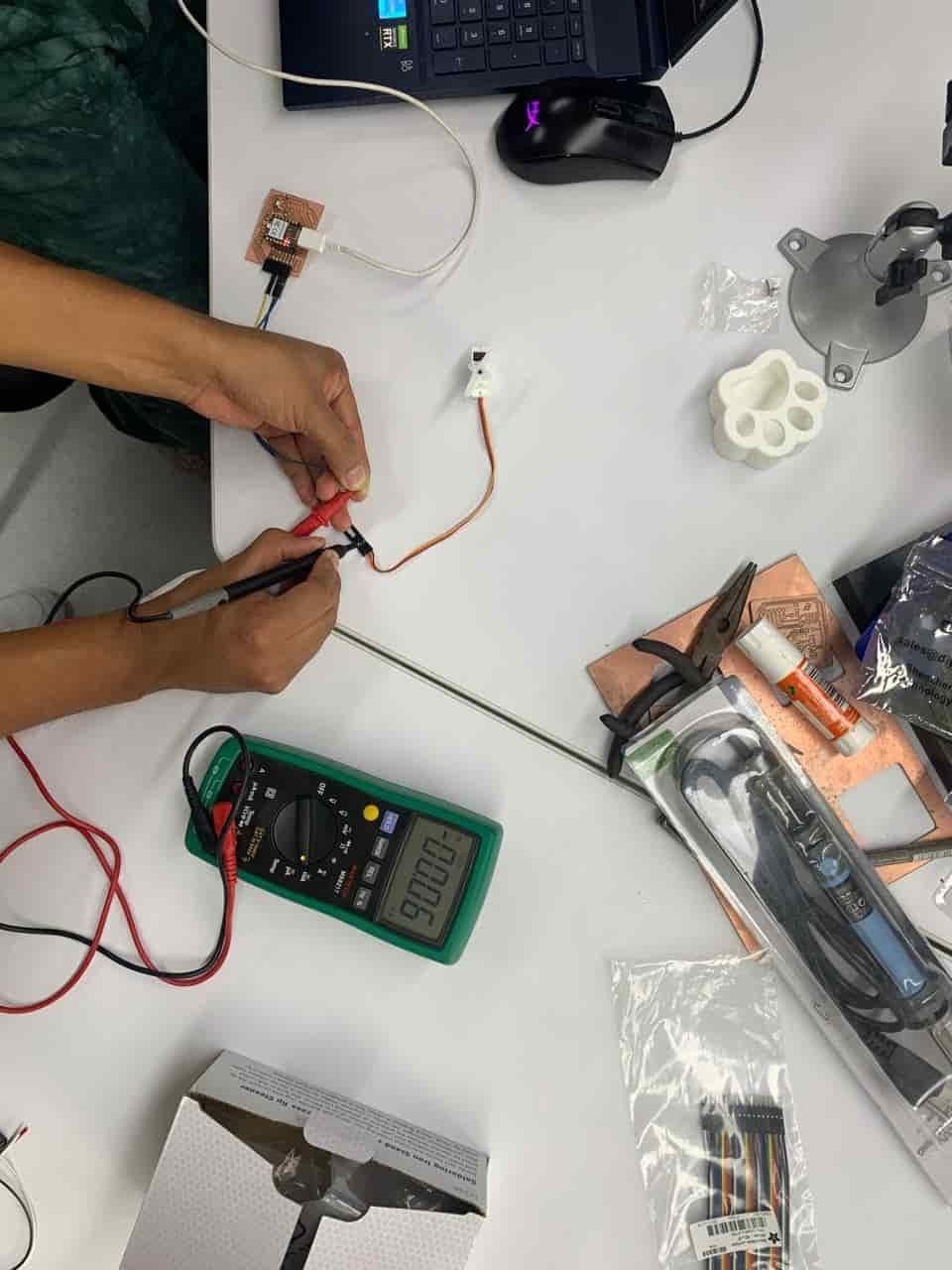
To evaluate power consumption, we initially used a multimeter and an oscilloscope. Next, we present our analysis of the servo motor:
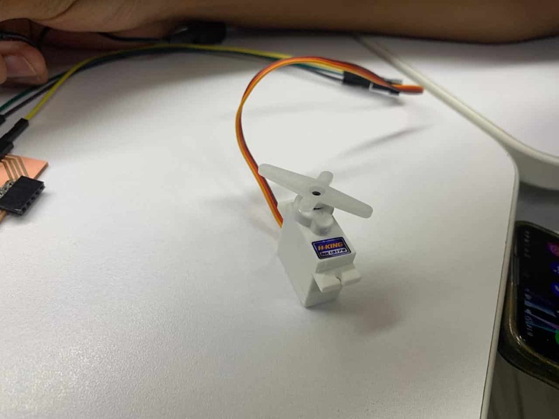
First, we determine the VOLTAGE necessary for the operation of the SERVOMOTOR. We place the COM terminal of the multimeter on the GND terminal of the SERVOMOTOR and the POSITIVE terminal on the 5V of the MOTOR. This gave us a voltage reading that ranged between 4.65 and 4.68 volts, indicating the voltage required by the SERVOMOTOR for its operation.

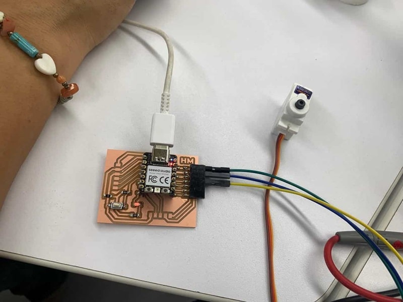
Next, we proceeded to measure the current in amperes consumed by the SERVOMOTOR. To do this, we established a series connection, connecting the COM terminal and the mA to other points of the 5V. Subsequently, we performed the measurement in mA and obtained the following results.

As with voltages, we observe that the servomotor current varies according to its movement, generating different consumption values.
Once the VOLTAGE (V) and INTENSITY (mA) measurements have been obtained, we calculate the SERVOMOTOR consumption using the formula: POWER (WATTS) = VOLTAGE(V) x CURRENT(A) POWER = 4.66V X 0.03033 A = 0.14W THE SERVOMOTOR CONSUMES 0.14 WATTS
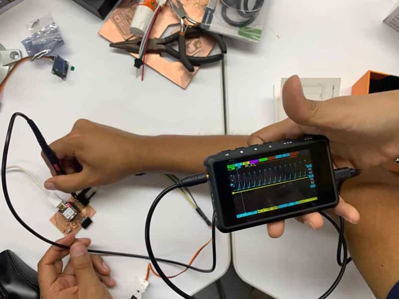
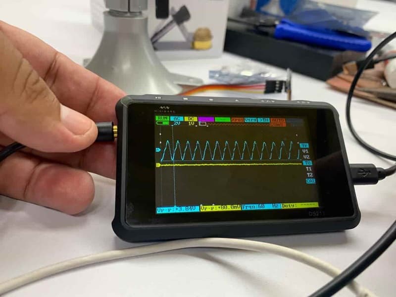
I also performed analysis using an oscilloscope to visualize the signal. To do this, we connect the tip of the oscilloscope to the data output and the ground to GND of the board. We observe a constant signal.