Safety training and detailed process characterization are critical steps in computer-controlled cutting. The combination of specialized tools and software guarantees a precise and efficient approach, maximizing quality and safety in production.
The first critical phase in the computer-controlled cutting process is laboratory safety training. Before carrying out any operation, it is essential that personnel are fully informed and trained in the relevant safety measures. This includes understanding and applying safety protocols, proper use of personal protective equipment, and familiarization with emergency evacuation routes. Training should also address potential risks associated with computer-controlled cutting machines, thereby promoting a safe and efficient work environment.
Once safety training is completed, process characterization is essential to ensure accurate and safe results in computer-controlled cutting. This characterization covers several key aspects:
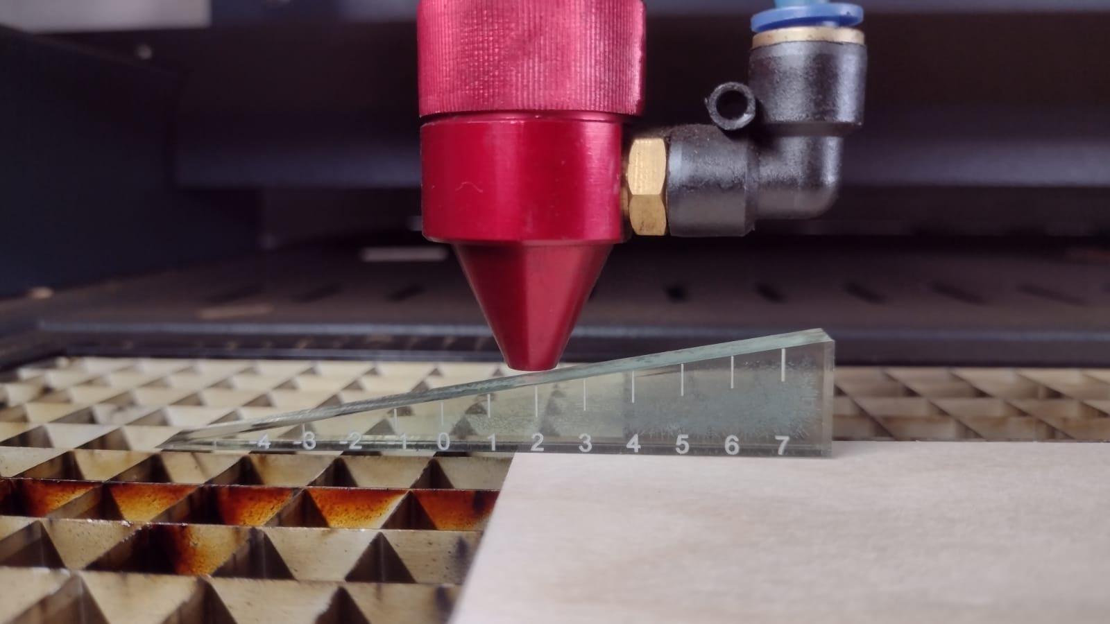
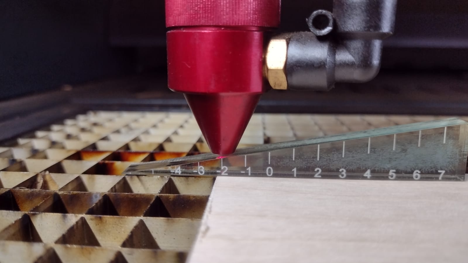
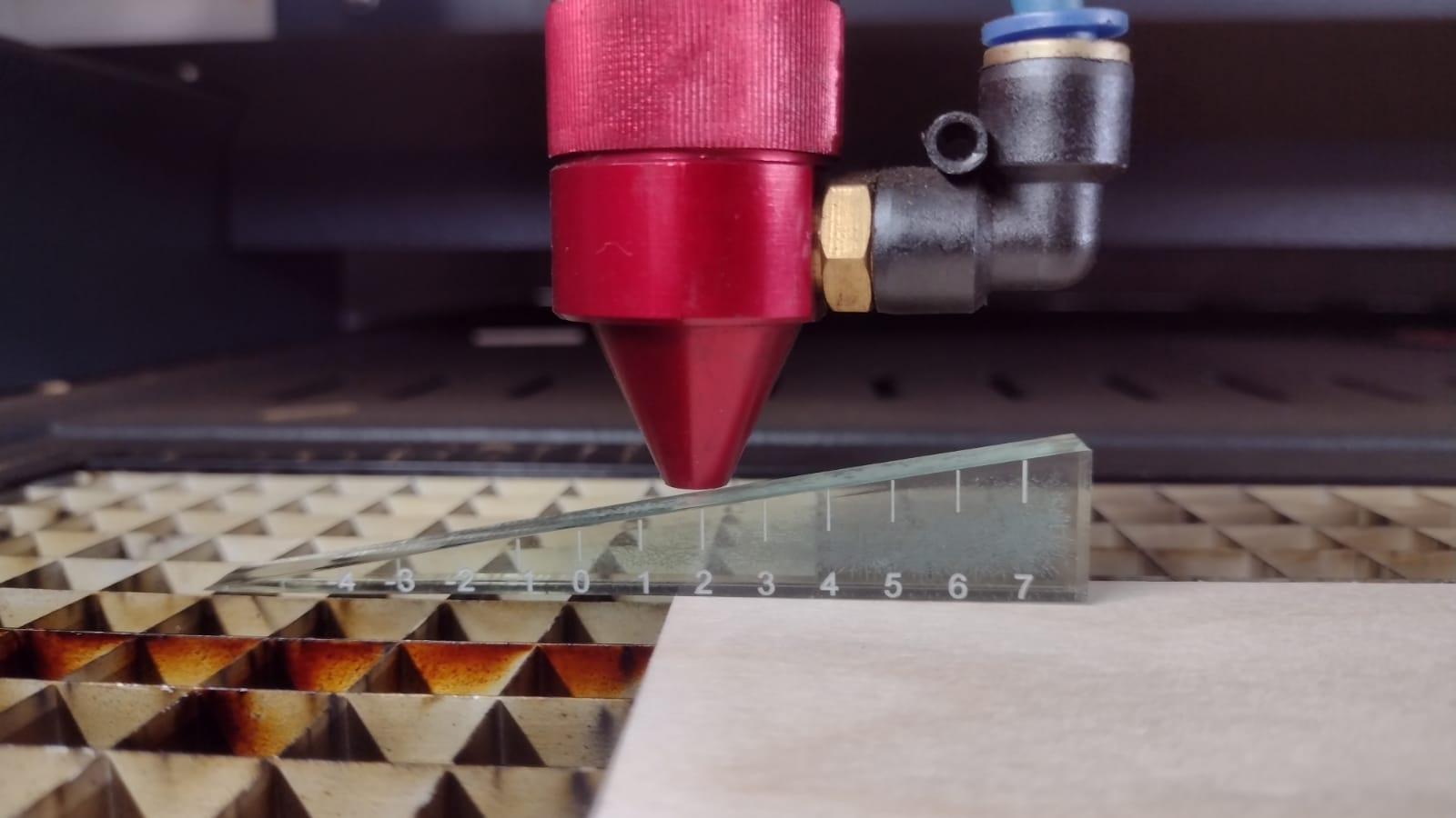
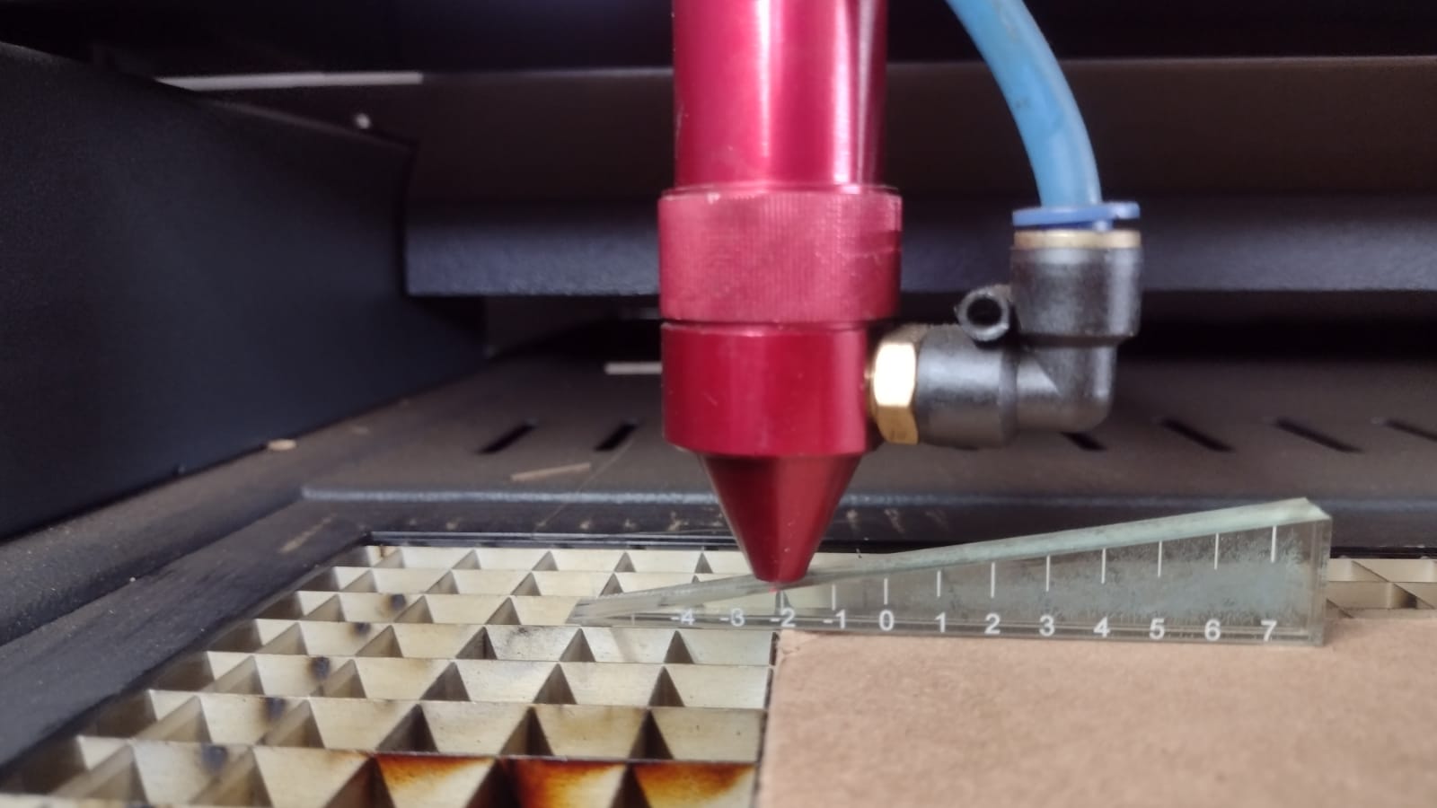
a) Focus: Accuracy of focus is crucial for clean, detailed cuts. Precise adjustments must be made to suit the specific material and design requirements.
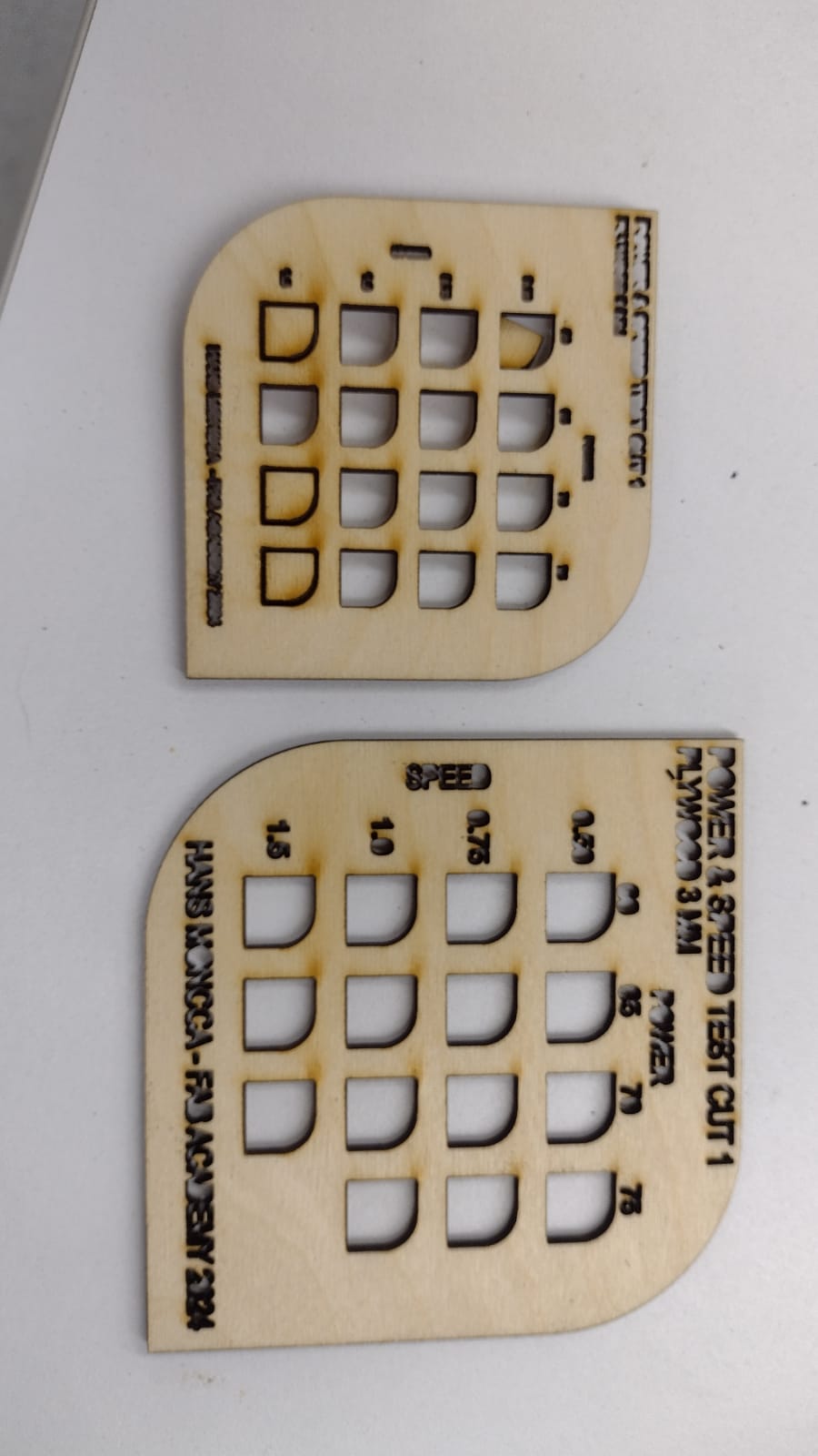
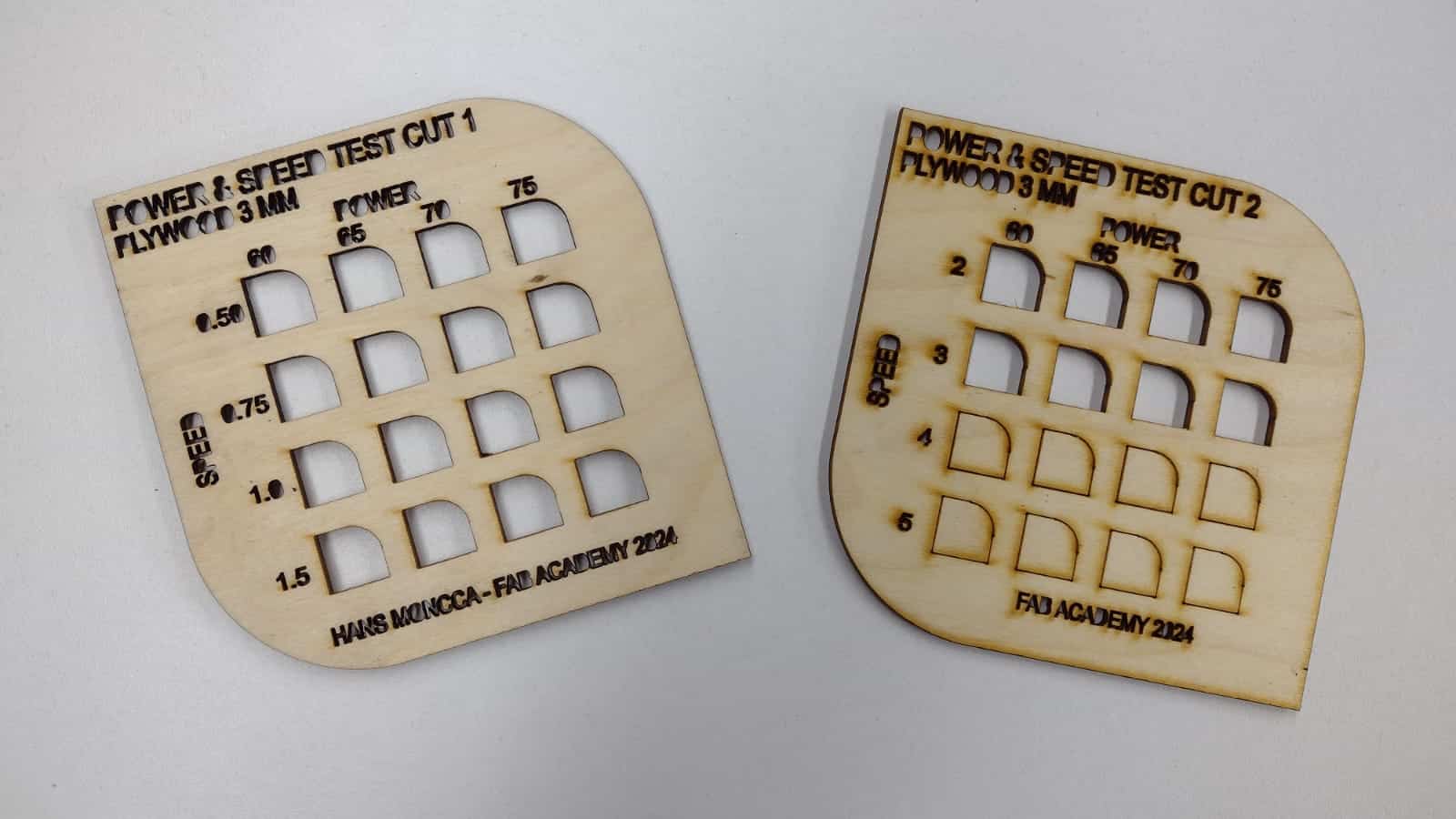
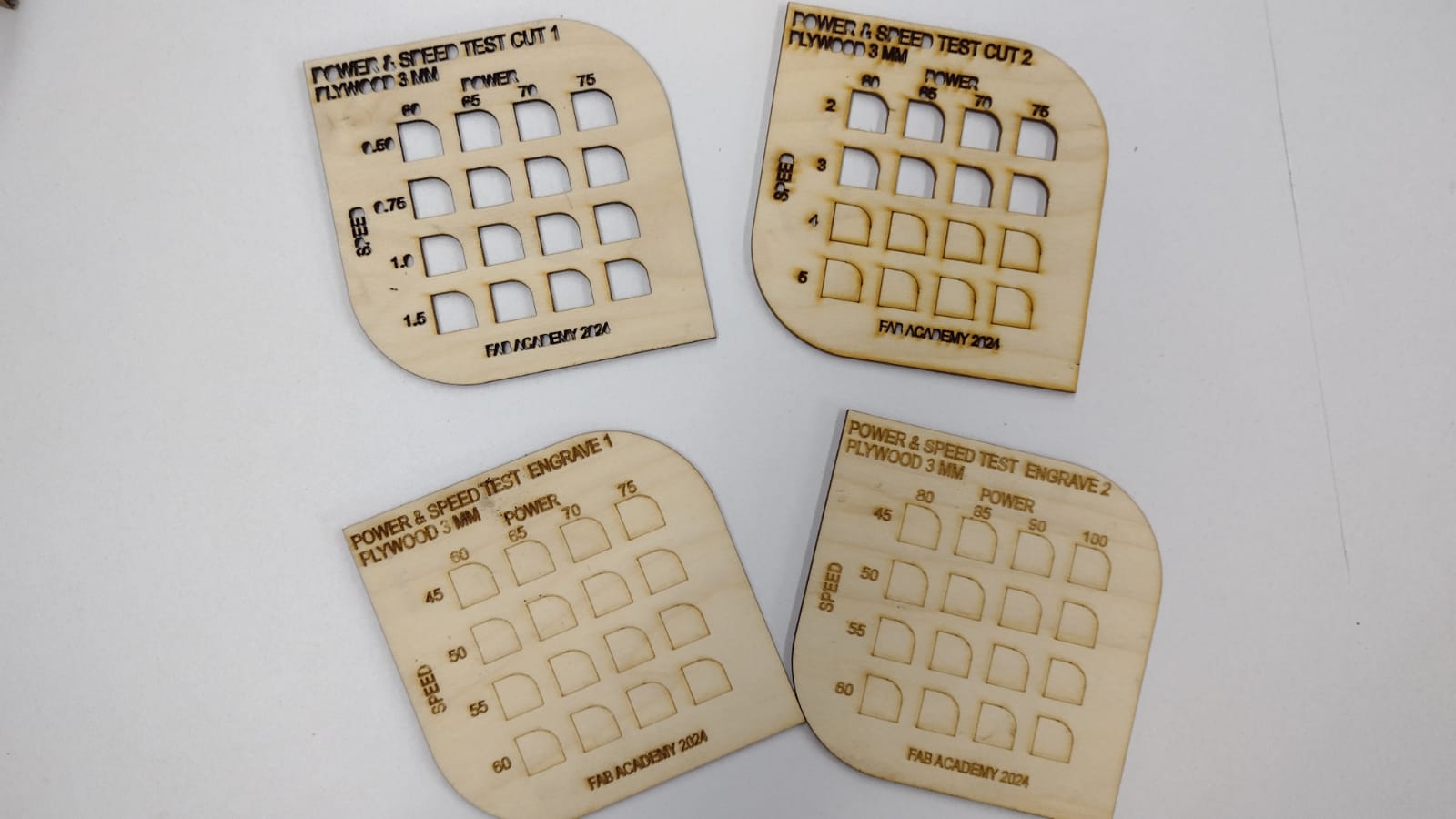
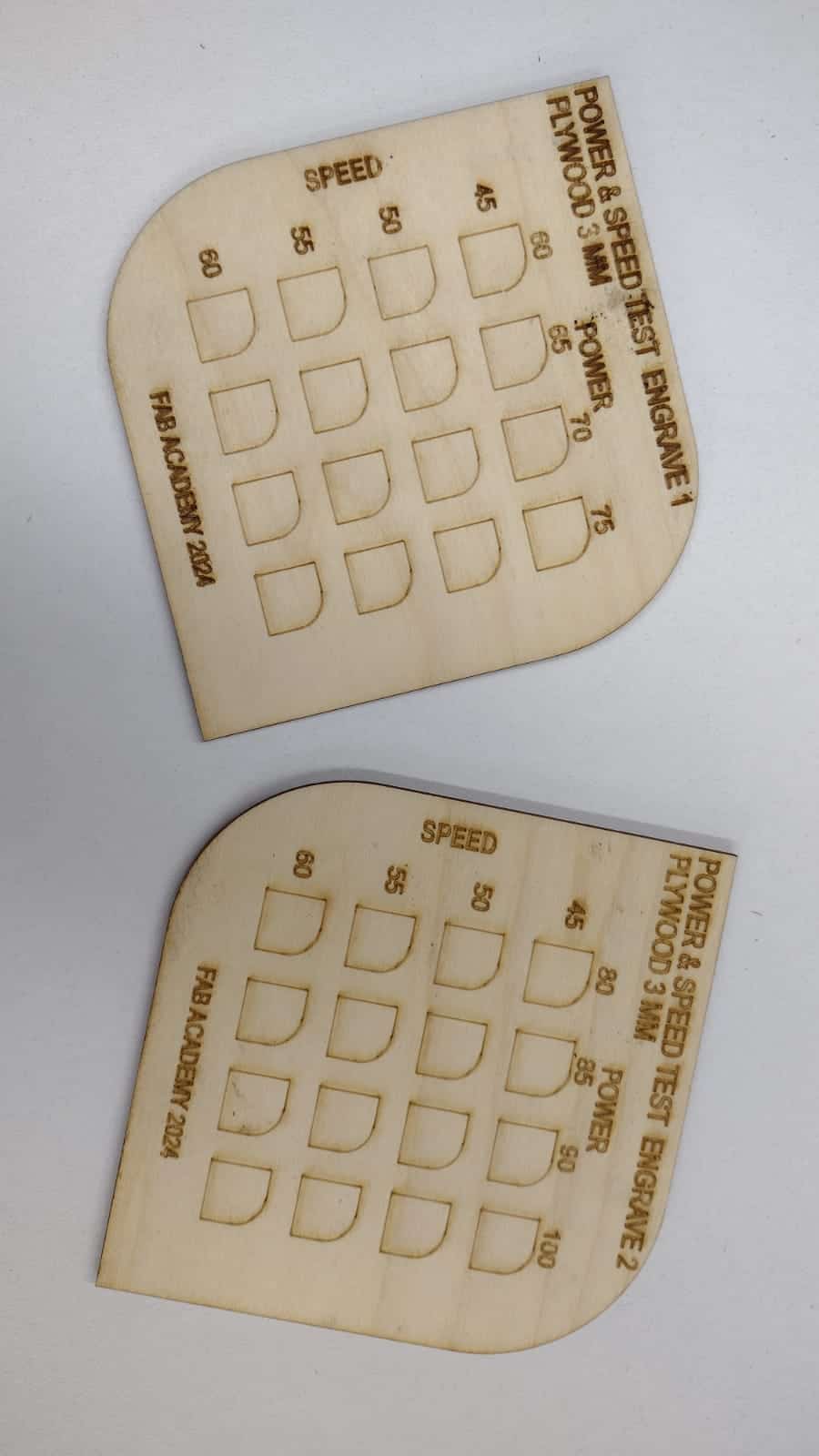
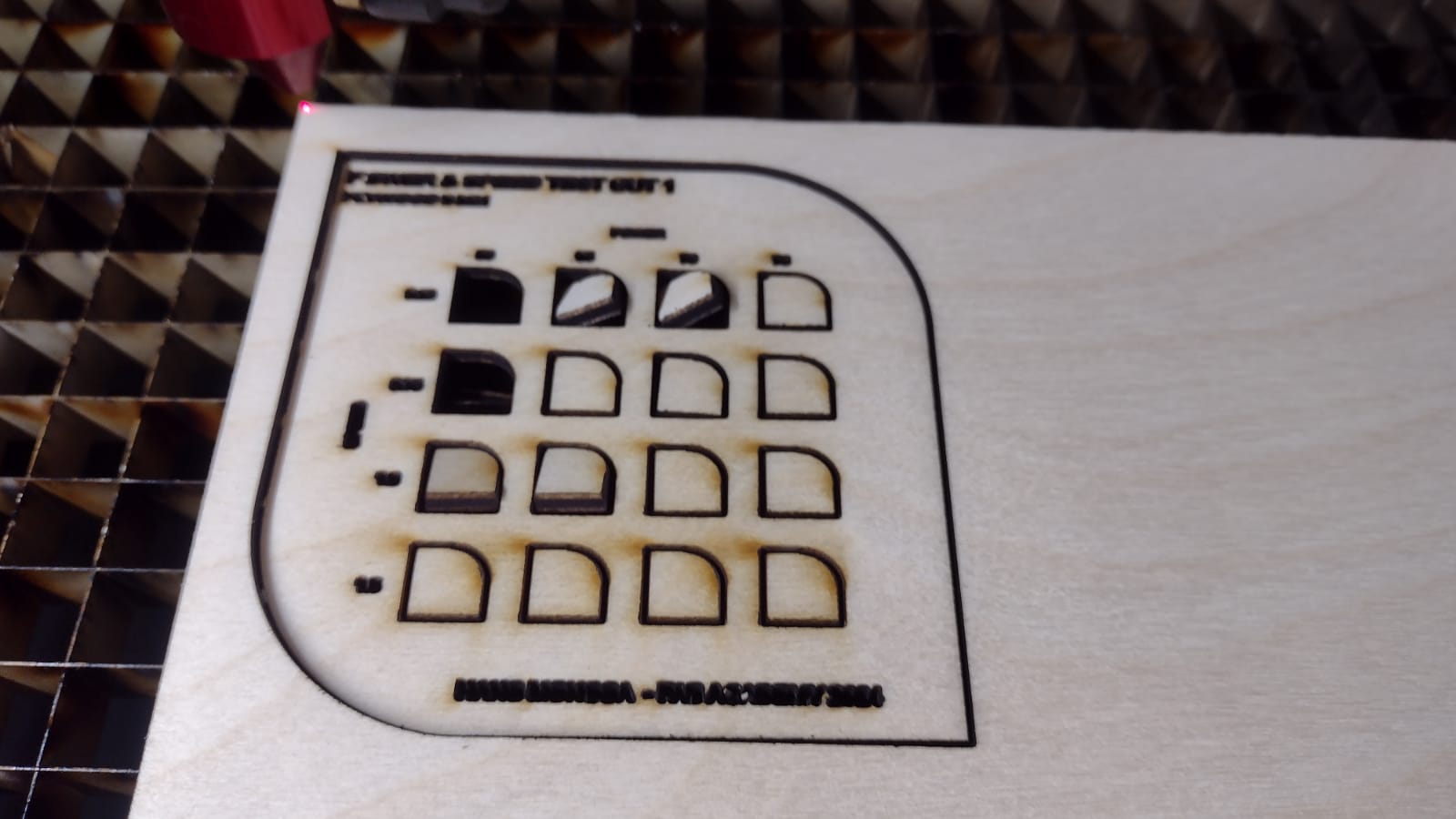
b) Power: The power of the cutting machine must be calibrated according to the properties of the material. Too much power can result in damage or deformity, while not enough power can result in incomplete cuts.
c) Cutting Speed: Cutting speed directly impacts the efficiency and quality of the final result. The characterization must determine the optimal speed for each material.
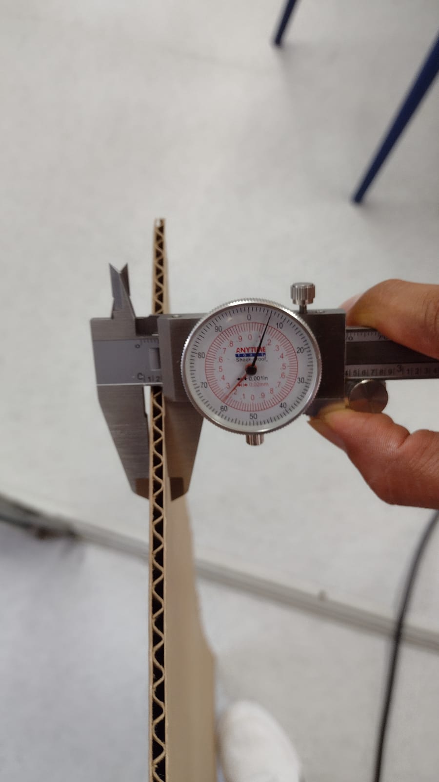
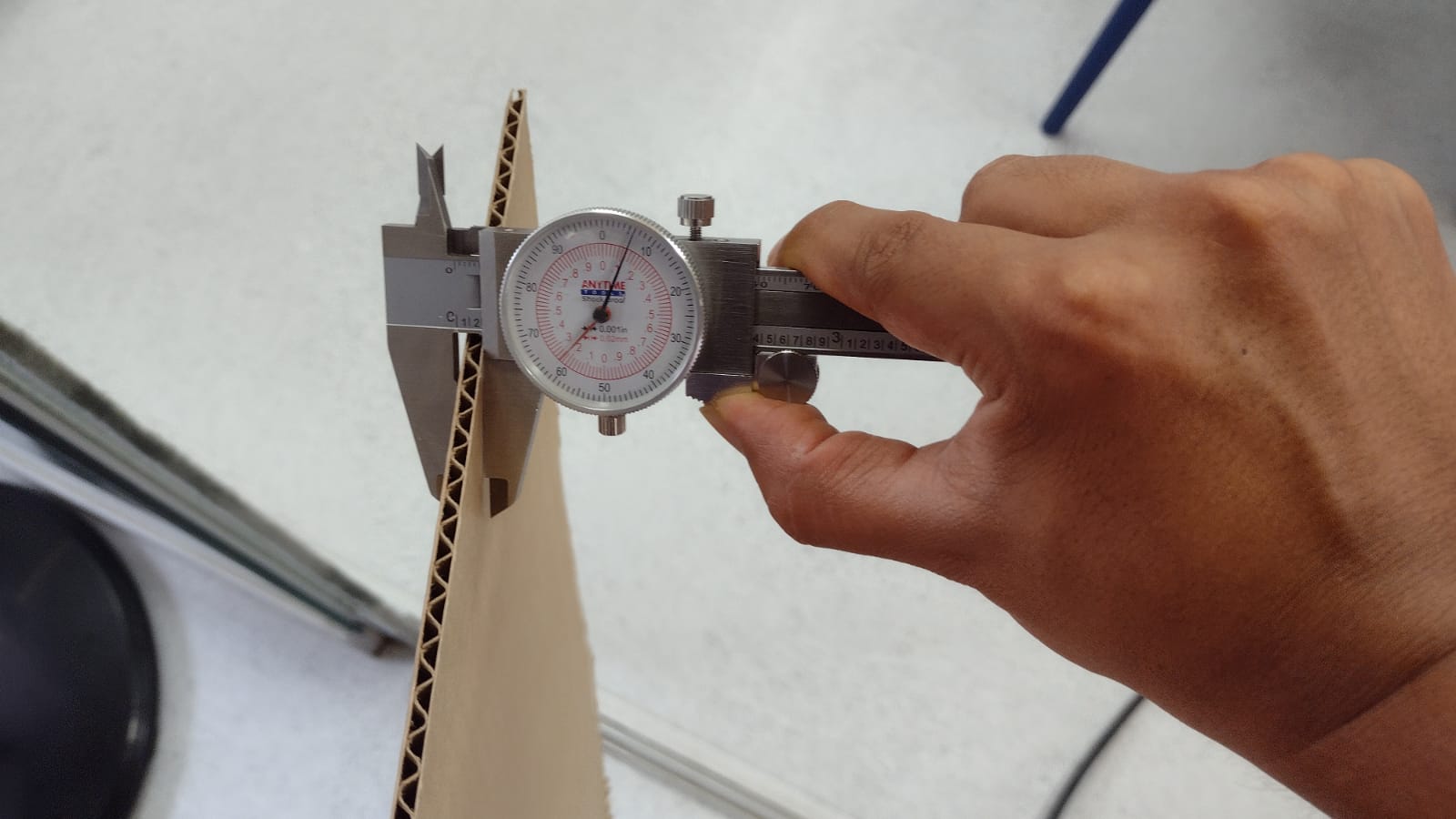
d) Joint Clearance: Accuracy in joint clearance is essential to avoid interference and ensure the structural integrity of the cut pieces. The characterization must establish the appropriate tolerances.
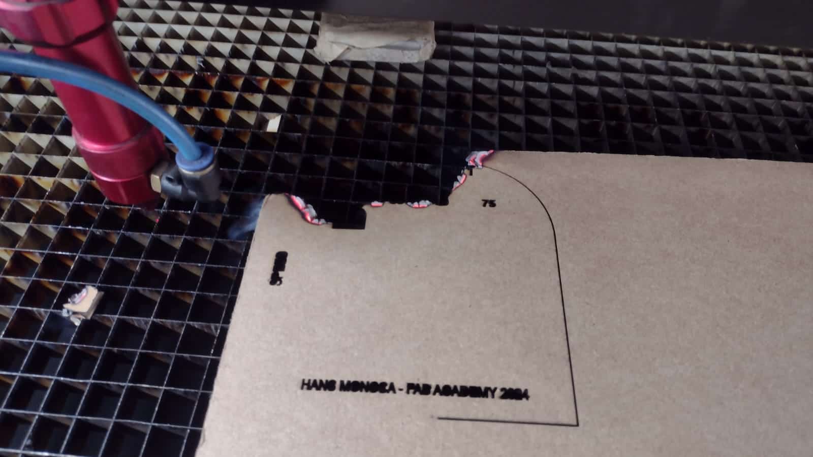
e) Cut Types: Different types of cuts, such as straight, curved and angled cuts, must be explored and characterized to ensure the versatility of the machine and its ability to meet various design needs.
a) Raster and Vector Software: The use of raster and vector software allows for the precise conversion of images and graphics into data that can be efficiently interpreted and executed by the cutting machine.
b) 2D and 3D Software: In modeling and design, the use of 2D and 3D software is essential. 2D software helps in creating detailed plans, while 3D software provides a three-dimensional representation for a more complete visualization of the project.
c) Rendering and Animation: Rendering and animation are useful for simulating the cutting process before physical execution, allowing for prior adjustments and optimizations.
d) Simulators: The use of simulators is crucial to anticipate possible problems and adjust the parameters before starting the actual cutting process.
e) SolidWorks: Software like SolidWorks facilitates detailed 3D design, providing powerful tools for modeling components and assemblies.
This assignment not only drives practical understanding of computer-controlled cutting, but also creativity in design and the ability to efficiently document and communicate the process and end result.
Before addressing the individual assignment, it is essential to complete extensive safety training for the computer-controlled cutting laboratory. This includes understanding emergency procedures, safe use of machines, proper material handling, and personal protection. The importance of following safety regulations will be emphasized to ensure a safe work environment.

The first individual task will be to cut something using the vinyl cutter. Each participant is expected to choose their own design and apply the cutting techniques to the vinyl, becoming familiar with the computer-controlled cutting process in this specific context.
a. Design Approach: Use a parametric approach that allows adaptability of the kit for different uses and configurations. img src="image.jpg" alt="">
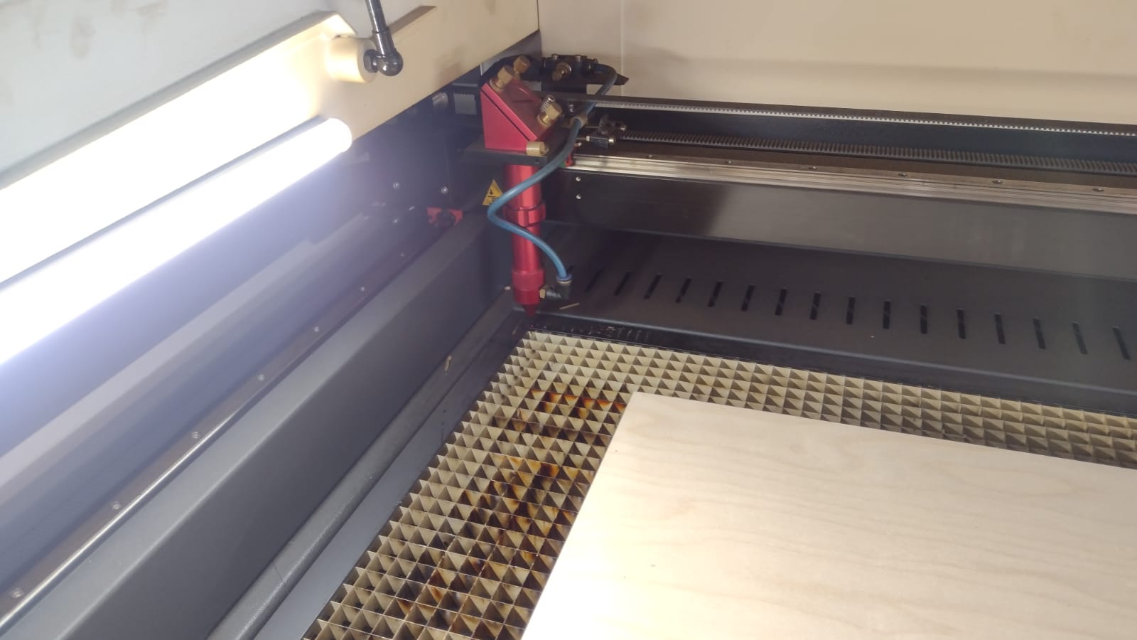
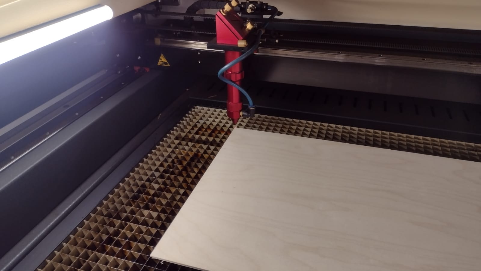
b. Laser Cutting Power and Speed: Adjust laser cutting power and speed optimally to ensure precise and efficient cuts on selected materials.
c. Joint Clearance: Carefully consider joint clearance in the design, ensuring a solid and stable assembly of the kit.
d. Assembly Types: Explore different types of assembly that allow for the versatility of the kit. Include clear instructions for each mounting option.
e. Non-Plane Elements: For extra credit, incorporate three-dimensional elements or non-planar structures into the kit design. This could include hinged connections, moving parts, or components that require three-dimensional assembly.
During the execution of the assignment, participants are expected to use a combination of specialized software. This includes computer-aided design (CAD) software such as SolidWorks for creating 3D models, vector software for precisely defining cuts, and simulation programs for evaluating kit functionality. Additionally, participants will be encouraged to visually render their designs for more effective presentation and understanding of the final product.
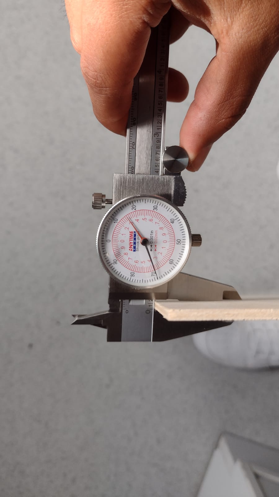
It is crucial to document every step of the process, from initial design to kit assembly. This will include pictures, precise measurements, detailed instructions, and any adjustments made during the process. Complete documentation will ensure thorough evaluation of the work performed and facilitate replication of the kit by others.