This weeks assigmenat was to test output devices using different development boards so i stared with the neo pixel led that attached with my board,and i wanted to build something related to my project i tried to build a mosfet driver that i will used to test a spark generator
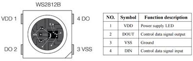
WS2812
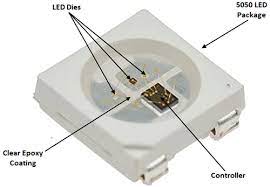
WS2812 is a type of addressable RGB LED (Light Emitting Diode) commonly used in various lighting and display applications. These LEDs are often referred to as NeoPixels, a trademarked name by Adafruit, one of the leading manufacturers of WS2812-based products.
The WS2812 LED integrates the LED die, control circuitry, and a communication interface into a single package, making it easy to control individual LEDs or groups of LEDs with a microcontroller or other digital control devices. Each WS2812 LED has a built-in shift register, which allows it to receive data serially and pass on the data to the next LED in the chain.
One of the key features of WS2812 LEDs is their ability to be individually addressed, meaning that each LED in a chain can be assigned a unique color and brightness. This makes them ideal for applications such as LED matrix displays, decorative lighting, and wearable electronics.
WS2812 LEDs communicate using a simple serial protocol, typically using a single data line to transmit color and brightness information to each LED in the chain. The communication protocol requires precise timing to ensure accurate data transmission, and there are various libraries and software tools available to simplify the process of controlling WS2812 LEDs with microcontrollers
So i used a basic programme to light up and run a animation on the single led
this is the sketch that i used for the WS2812B individual addressable led
    #include Adafruit_NeoPixel.h

      // Pin connected to the NeoPixels (WS2812B)
      #define LED_PIN 15

      // Number of NeoPixels
      #define LED_COUNT 1

      // Create NeoPixel object
      Adafruit_NeoPixel strip(LED_COUNT, LED_PIN, NEO_GRB + NEO_KHZ800);

      void setup() {
        // Initialize NeoPixel strip
        strip.begin();
        strip.show(); // Initialize all pixels to 'off'
      }

      void loop() {
        // Cycle through different colors
        rainbow(20); // Change colors every 20ms
      }

      // Function to cycle through rainbow colors
      void rainbow(uint8_t wait) {
        for (uint16_t i = 0; i < 256; i++) {
          uint32_t color = Wheel((i + strip.numPixels()) & 255);
          for (int j = 0; j < strip.numPixels(); j++) {
            strip.setPixelColor(j, color);
          }
          strip.show();
          delay(wait);
        }
      }

      // Input a value 0 to 255 to get a color value.
      // The colors are a transition r - g - b - back to r.
      uint32_t Wheel(byte WheelPos) {
        WheelPos = 255 - WheelPos;
        if (WheelPos < 85) {
          return strip.Color(255 - WheelPos * 3, 0, WheelPos * 3);
        }
        if (WheelPos < 170) {
          WheelPos -= 85;
          return strip.Color(0, WheelPos * 3, 255 - WheelPos * 3);
        }
        WheelPos -= 170;
        return strip.Color(WheelPos * 3, 255 - WheelPos * 3, 0);
      }
HOW DOES THE CODE WORK
#include Adafruit_NeoPixel.h: This line includes the Adafruit NeoPixel library, which provides functions to control WS2812B LEDs.
#define LED_PIN 15: This line defines the pin to which the data line of the WS2812B LED strip is connected. In this case, it's pin 15.
#define LED_COUNT 1: This line defines the number of LEDs in the LED strip. In this case, there is only one LED.
Adafruit_NeoPixel strip(LED_COUNT, LED_PIN, NEO_GRB + NEO_KHZ800): This line creates a NeoPixel object named strip. It initializes the object with the number of LEDs (LED_COUNT), the pin connected to the LEDs (LED_PIN), and the color order and communication speed (NEO_GRB + NEO_KHZ800). Here, NEO_GRB specifies the color order (red, green, blue), and NEO_KHZ800 specifies the communication frequency (800 KHz).
void setup(): This function is called once when the Arduino board starts up. It initializes the NeoPixel strip.
strip.begin(): This line initializes the NeoPixel strip.
strip.show(): This line sends the initial color data to all pixels in the strip, turning them off initially.
void loop(): This function is called repeatedly in a loop after the setup() function. It contains the main code logic.
rainbow(20): This line calls the rainbow() function with a delay of 20 milliseconds. This function changes the color of the LED strip in a rainbow pattern.
void rainbow(uint8_t wait): This function defines the rainbow effect. It cycles through different colors of the rainbow with a delay specified by the wait parameter.
for (uint16_t i = 0; i < 256; i++) { ... }: This loop iterates through 256 color values to create the rainbow effect.
uint32_t color = Wheel((i + strip.numPixels()) & 255): This line calculates the color for the current position in the rainbow using the Wheel() function.
strip.setPixelColor(j, color): This line sets the color of each pixel in the strip to the calculated color.
strip.show(): This line updates the LED strip with the new color data.
delay(wait): This line pauses the execution for the specified delay time.
uint32_t Wheel(byte WheelPos): This function calculates the color for a given position in the rainbow. It takes a value between 0 and 255 and returns a corresponding color value. The colors transition from red to green to blue and back to red.
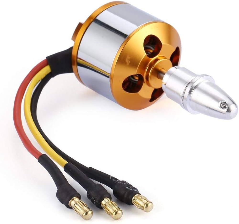
ESC (Electronic Speed Controller) and BLDC Motors
Brushless DC Motor
As the name suggests, BLDC motors do not use brushes and a commutator. Instead:
The rotor of a BLDC motor is a permanent magnet.
The coils that generate the magnetic fields are fixed in place on the stator and do not rotate.
There are no brushes needed to pass current to rotor coils since the coils are stationary.
In contrast to brushed motors where rotation is controlled by current through rotor coils:
BLDC motors achieve rotation by controlling the magnetic fields generated by the stationary coils on the stator.
The permanent magnet rotor rotates, responding to changes in the magnetic fields produced by the stator coils.
To control the speed and direction of rotation, you adjust the magnitude and direction of current flowing through the stator coils.
This design offers advantages such as improved efficiency, higher reliability, and reduced maintenance compared to brushed motors.
How BLDC Motors Work with ESC
BLDC motors operate based on ESC control:
ESC commutates motor phases to drive rotor rotation.
BLDC motors deliver efficient, reliable performance ideal for various applications.
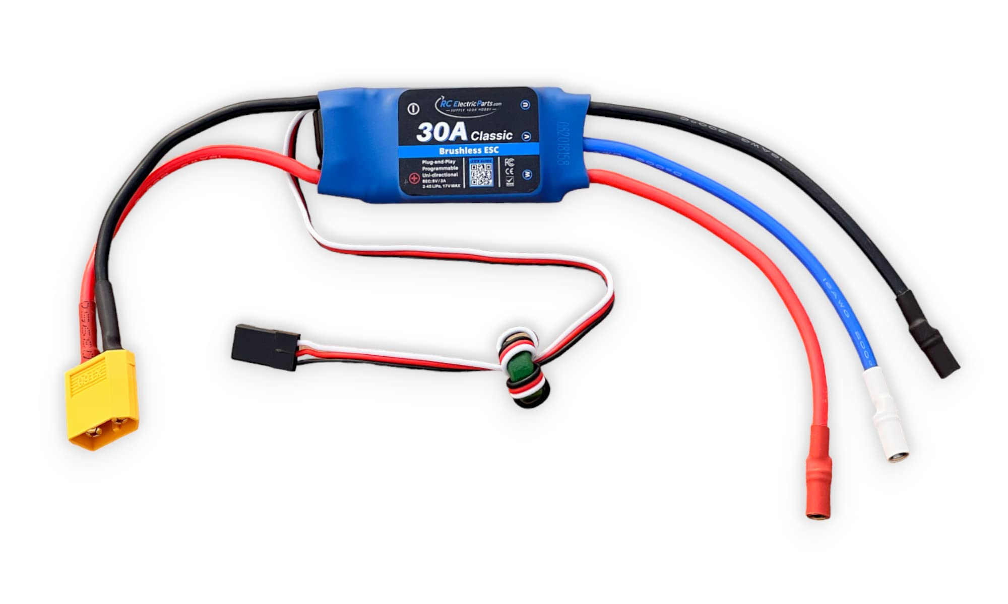
ESC (Electronic Speed Controller)
An Electronic Speed Controller (ESC) is a device used to control the speed of an electric motor, crucial in applications like RC vehicles, drones, and more. It utilizes Pulse Width Modulation (PWM) signals for precise speed control.
Principles of ESC
An ESC regulates the speed of electric motors, such as BLDC (Brushless DC) motors, which are widely used due to their efficiency and performance advantages over brushed motors.
PWM (Pulse Width Modulation)
PWM is key to an ESC’s function. It encodes analog signals digitally, determining motor speed based on the duty cycle of the signal it receives:
Signal Input: ESCs receive PWM signals, often from microcontrollers, dictating motor speed.
Duty Cycle: The duty cycle (ratio of signal high-time to total period) controls average voltage to the motor:
High Duty Cycle: Increases motor speed by elevating average voltage.
Low Duty Cycle: Slows motor by reducing average voltage.
Smooth Control: ESCs ensure smooth acceleration and deceleration, vital for stable operation.
Types of ESC
There are two main ESC types:
Brushed ESCs: Simple, for brushed motors.
Brushless ESCs (BLDC ESCs): Complex, for BLDC motors offering higher efficiency and performance.
Sensored BLDC Motors and ESCs
Sensored BLDC motors use feedback from sensors (Hall effect or similar) for precise motor control:
Three hall sensors provide rotor position data.
Wiring includes connections for motor phases and hall sensor outputs to the ESC.
Sensorless BLDC Motors and ESCs
Sensorless BLDC motors operate without sensors, relying on ESC algorithms to determine rotor position:
Wiring focuses on motor phases and power connections to the ESC.
ESC algorithms estimate rotor position for smooth operation.
HOW BLDC MOTOR WORK WITH ESC
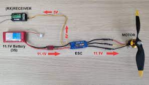
An Electronic Speed Controller (ESC) is essential for controlling Brushless DC (BLDC) motors, providing precise speed and direction control in various applications such as drones, RC vehicles, and industrial equipment. Here’s how ESCs work with BLDC motors:
1. Signal Processing
The ESC receives commands from a controller (like a microcontroller or transmitter/receiver system) via a PWM (Pulse Width Modulation) signal. This signal dictates the desired speed and direction of the motor.
2. Commutation
BLDC motors require precise commutation (switching of current in the motor windings) to generate the rotating magnetic field necessary for rotor movement. The ESC electronically commutates the motor by sequentially energizing the stator coils in the correct sequence based on rotor position feedback.
3. Rotor Position Sensing
To accurately commutate the motor, some ESCs use sensorless techniques that estimate rotor position based on back EMF (Electromotive Force) detection, while others employ sensors (such as Hall effect sensors) to directly measure rotor position.
4. Speed Control
The ESC adjusts the speed of the BLDC motor by varying the amplitude and timing of the current pulses sent to the motor windings. This control allows for precise speed regulation and response to changing load conditions.
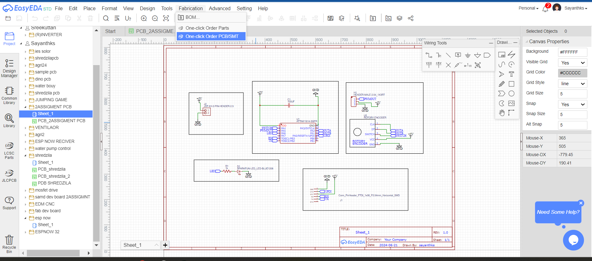
BUIDLING THE PCB
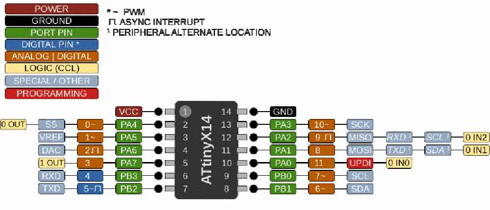
PCB Design with ATtiny1614 Microcontroller
Components Used:
ATtiny1614 Microcontroller: An 8-bit microcontroller with 16 KB Flash memory, commonly used in embedded systems.
By following these steps in EasyEDA, you can effectively design a PCB for programming with the ATtiny1614 microcontroller, ensuring proper component placement, routing, and design validation.
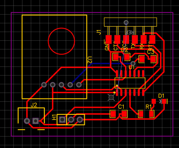
Converting Gerber to PNG Using OurPCB's Gerber Viewer
To convert Gerber files to PNG format, you can use OurPCB's Gerber Viewer tool. This tool allows you to visualize and convert Gerber files into more accessible image formats like PNG.
Steps to Convert Gerber to PNG:
Upload Gerber Files:
Go to Ourlabs Gerber Viewer website or platform.
Upload your Gerber files (.gbr, .gtl, .gbl, etc.) to the viewer.
View and Verify Layers:
Use the Gerber Viewer interface to view each layer of your PCB design.
Verify that all layers are correctly displayed and oriented.
Convert to PNG:
Locate the option or tool in the Gerber Viewer to export or convert the displayed layers to PNG.
Specify the resolution or settings for the PNG output if applicable.
Download PNG Files:
Once the conversion process is complete, download the PNG files generated from your Gerber layers.
The PNG files will represent each layer of your PCB design as an image file.
Converting Gerber files to PNG using OurPCB's Gerber Viewer tool simplifies the process of visualizing and sharing PCB designs. It allows you to inspect design layers and communicate design intent effectively.
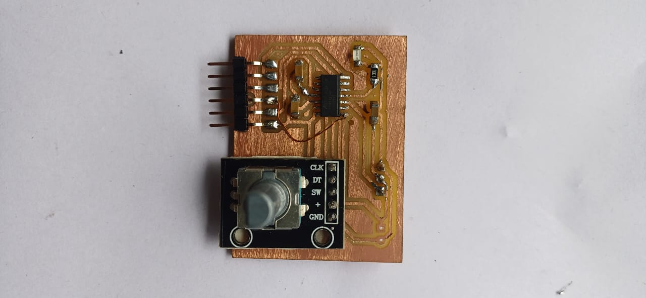
PRODUCTION
then i used fab modes to send the files to the milling machine and milled the pcb and assembled it
Controlling ESC with PWM
To control an ESC with PWM, a microcontroller or dedicated PWM signal generator sends pulses to the ESC. The width of each pulse (duty cycle) determines the motor speed.
    // Example code for controlling ESC with PWM
    #include <Servo.h>
      Servo esc;       // Create a servo object to control the ESC
      int ledPin = 2;  // LED pin

      void setup() {
        esc.attach(1);            // Attach ESC signal to pin 9
        pinMode(ledPin, OUTPUT);  // Set LED pin as output
          esc.writeMicroseconds(2000);  // Send 1000us pulse width
          delay(2000);
            esc.writeMicroseconds(1000);  // Send 1000us pulse width
            delay(1000);


      }

      void loop() {
        // Arm the ESC
        esc.writeMicroseconds(1000);  // Send 1000us pulse width
        digitalWrite(ledPin, HIGH);   // Turn on LED
        delay(2000);                  // Wait for ESC to arm

        // Increase throttle gradually
        for (int throttle = 1000; throttle <= 2000; throttle += 10) {
          esc.writeMicroseconds(throttle);  // Set throttle
          delay(20);                        // Delay between increments
        }
        delay(2000);  // Hold throttle at maximum

        // Decrease throttle gradually
        for (int throttle = 2000; throttle >= 1000; throttle -= 10) {
          esc.writeMicroseconds(throttle);  // Set throttle
          delay(20);                        // Delay between decrements
        }
        esc.writeMicroseconds(1000);  // Set throttle back to minimum
        digitalWrite(ledPin, LOW);    // Turn off LED
        delay(2000);                  // Wait before repeating
      }
ESC Control Code Explanation
Setup Function (setup())
Initialization:
Connects the ESC signal to pin 1 of the Arduino.
Sets pin 2 as an output for controlling an LED.
ESC Initialization:
Sends a signal (pulse) to the ESC:
Initially, a 2000 microsecond pulse (2 milliseconds) to initialize the ESC.
After a delay of 2 seconds, sends a 1000 microsecond pulse to arm the ESC.
Loop Function (loop())
Arming the ESC:
Sends a 1000 microsecond pulse to arm the ESC, turning on an LED for visual indication.
Waits for 2 seconds to ensure the ESC is ready.
Throttle Control:
Increasing Throttle:
Gradually increases the throttle from low to high:
Starts from 1000 microseconds and increments by 10 microseconds every 20 milliseconds until it reaches 2000 microseconds (maximum throttle).
Holds maximum throttle for 2 seconds.
Decreasing Throttle:
Gradually decreases the throttle from high to low:
Starts from 2000 microseconds and decrements by 10 microseconds every 20 milliseconds until it returns to 1000 microseconds.
Resets the throttle to 1000 microseconds, effectively stopping the motor (if connected).
Turns off the LED.
Loop Execution:
Repeats the throttle control sequence after a 2-second delay.