This week as just amazing from the globel classs it self i had thet understandging that we will b e doing a lot of hands on stuff this week and yes indeed we did we primerly focused on cutting 2d shapes from vinyal stikers and cardbord along with that this week we also did a groups assigmennt that helped the entire team to have fun and was a good start for the comming weeks
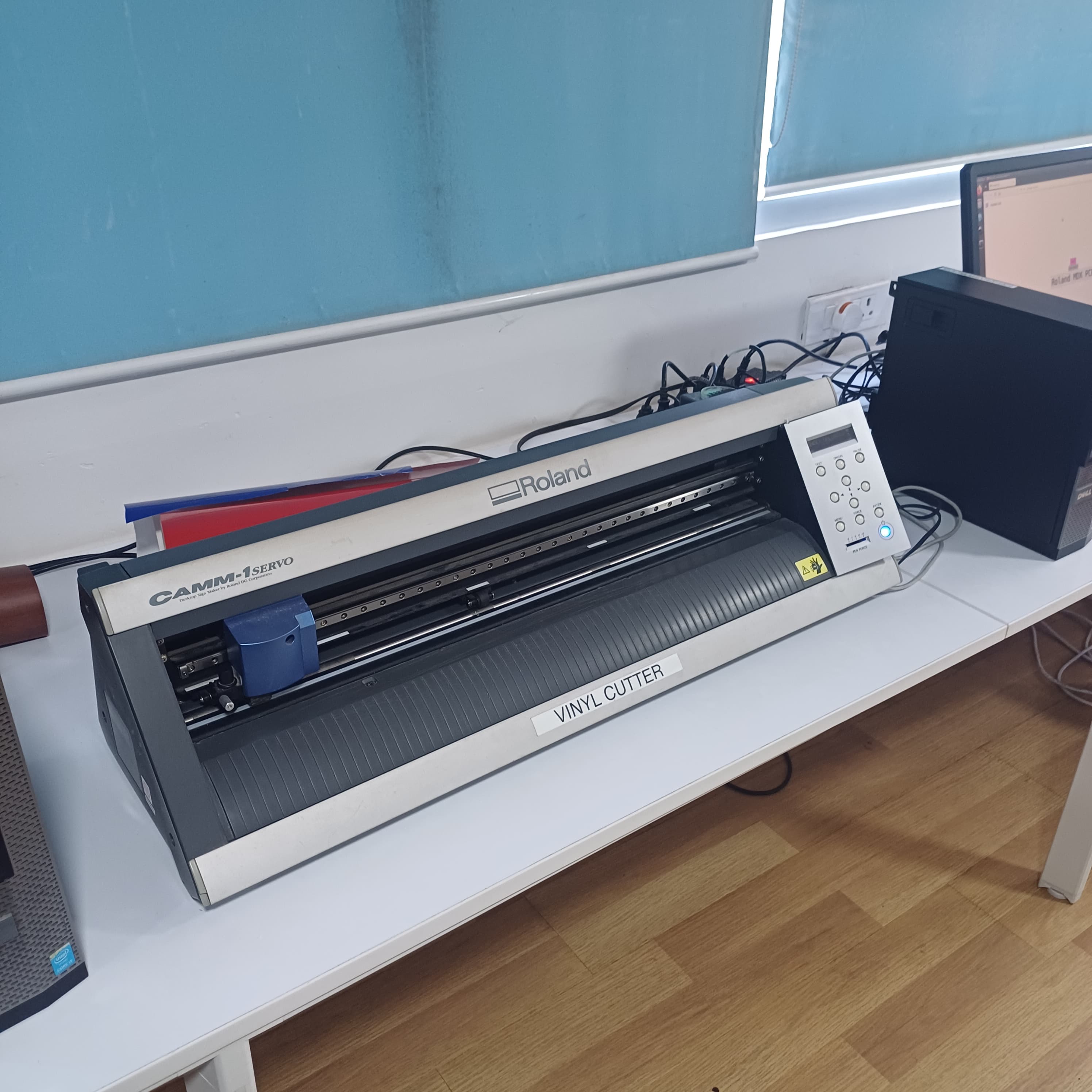
the first machine that us was introduced was the vinyl cutter it used a plastic vinyall shhet as the stock materil and used a thin metal knife to cut the material it was a 2 axis machine with pasive knife controlls and the make is,The machine referred to is the Roland GS24. This vinyl cutter is well-known for its precision cutting capabilities and user-friendly interface. It has been widely used in various industries for cutting vinyl sheets and other similar materials with high accuracy.
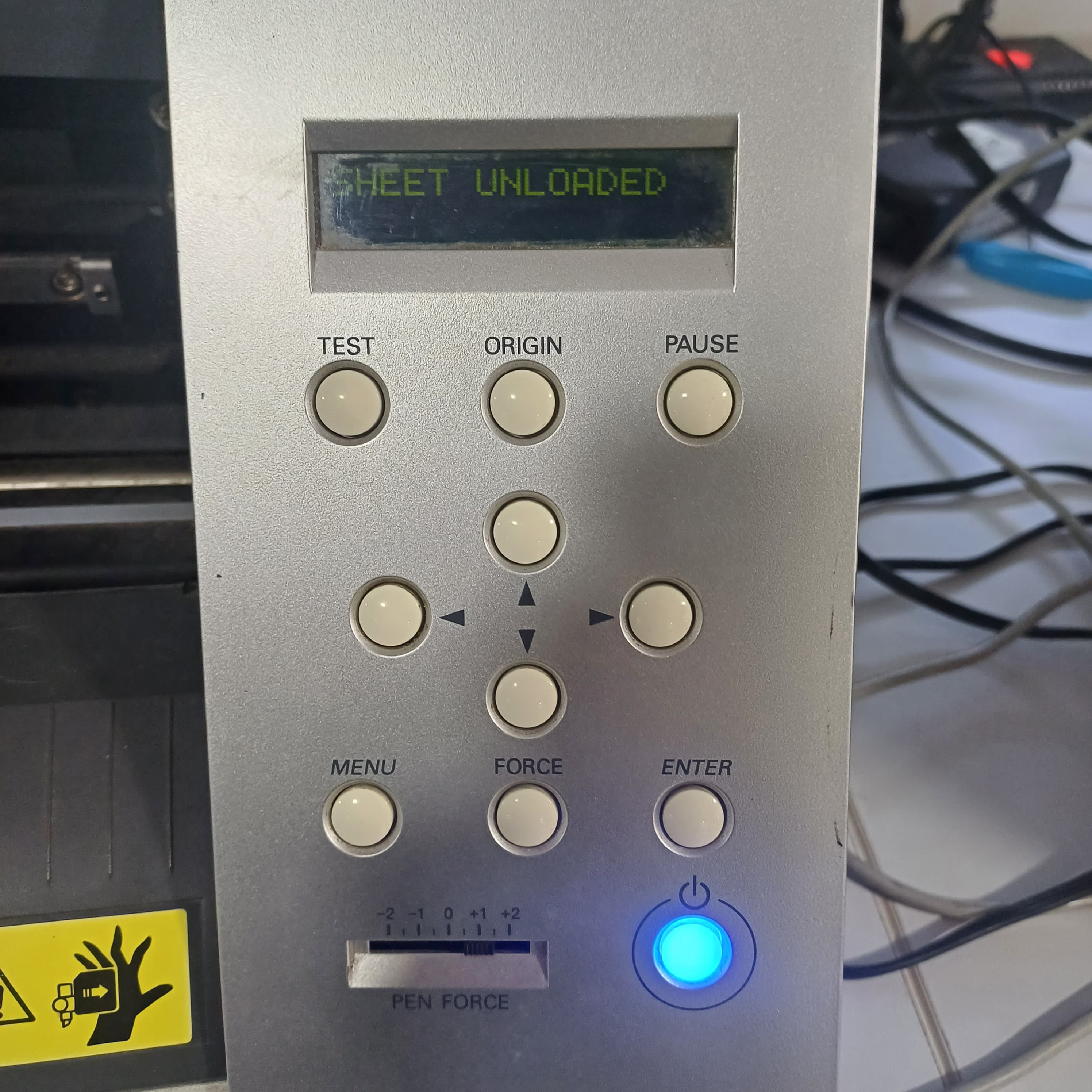
in oder to cut a test part there was a button wicth when clicked will cut a sample round with a squre inside ,the machine also fetures knife force adjustmenst xy jogging switches and orgin set button
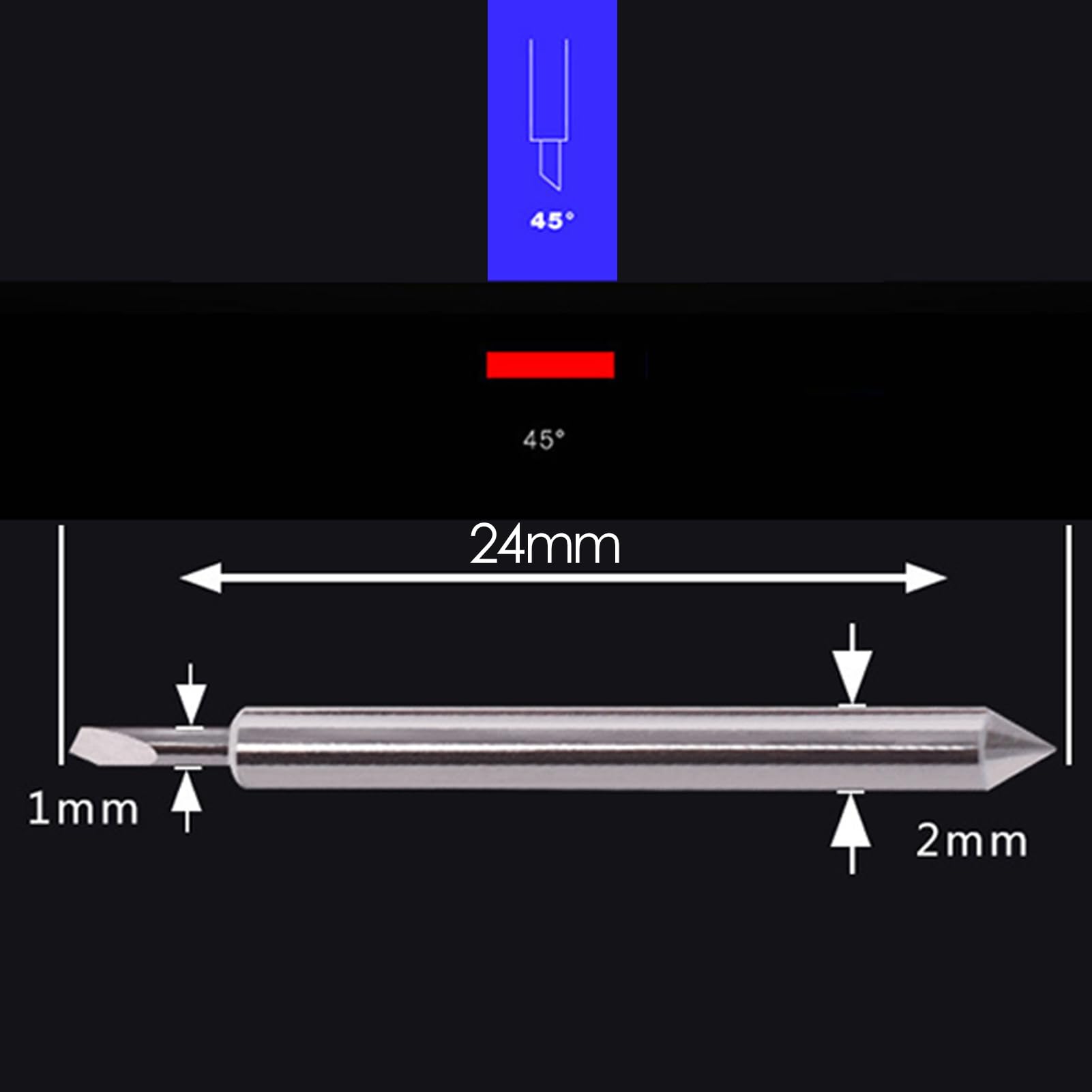
The blade of a vinyl cutter machine is a small, precise cutting tool designed to slice through vinyl and other thin materials with high accuracy. Here's how it works:
The blade is typically made of durable, high-quality steel to maintain sharpness and precision over time. It is small and pointed, often with an angled tip to facilitate clean cuts. The blade is mounted in a holder that allows it to rotate freely, ensuring it can adjust its orientation as it follows the cutting path.
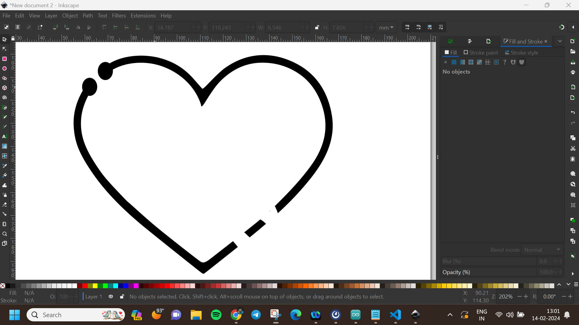
File > Import and select the JPEG image you want to convert.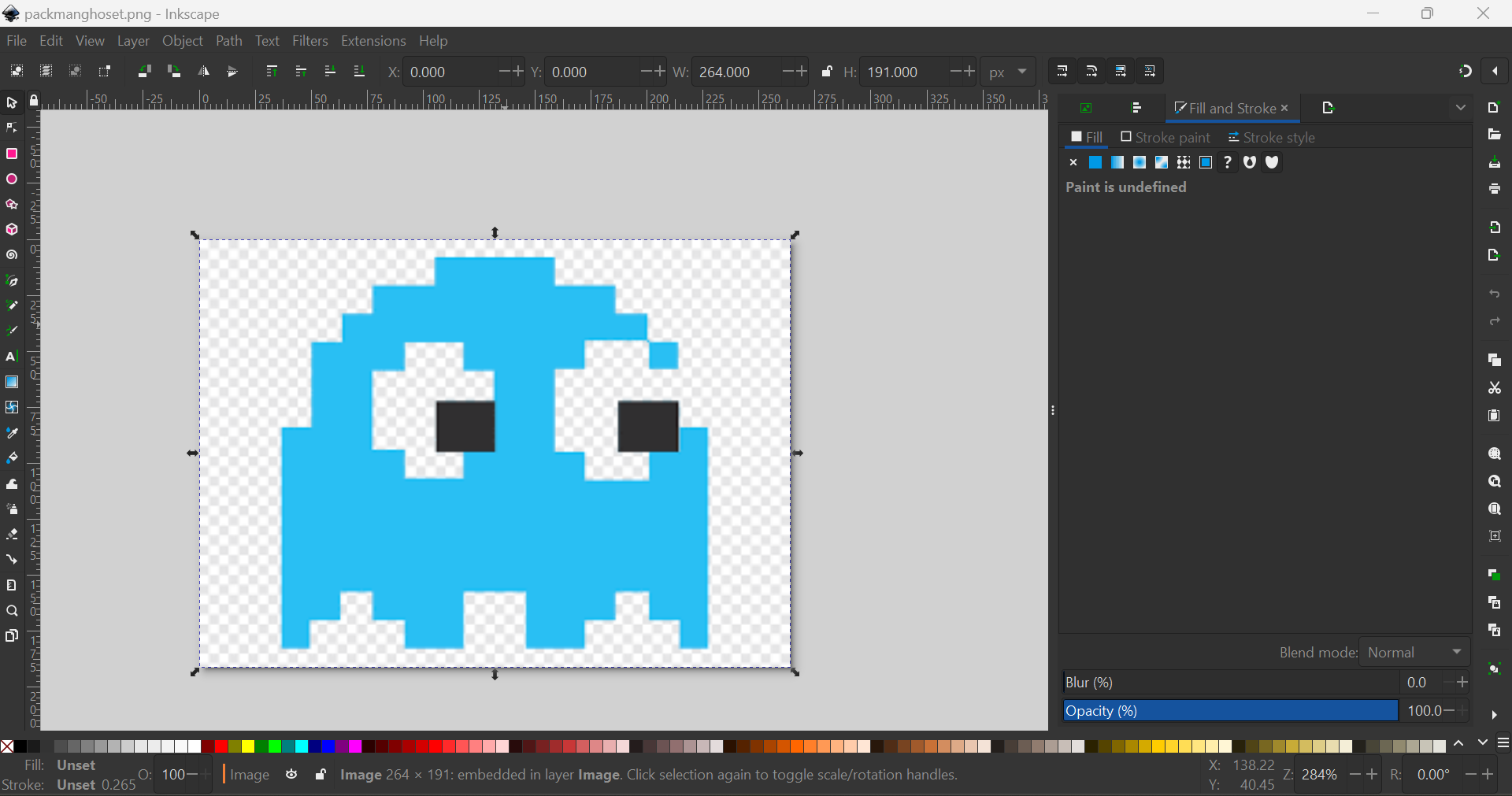
Path > Trace Bitmap to open the Trace Bitmap dialog.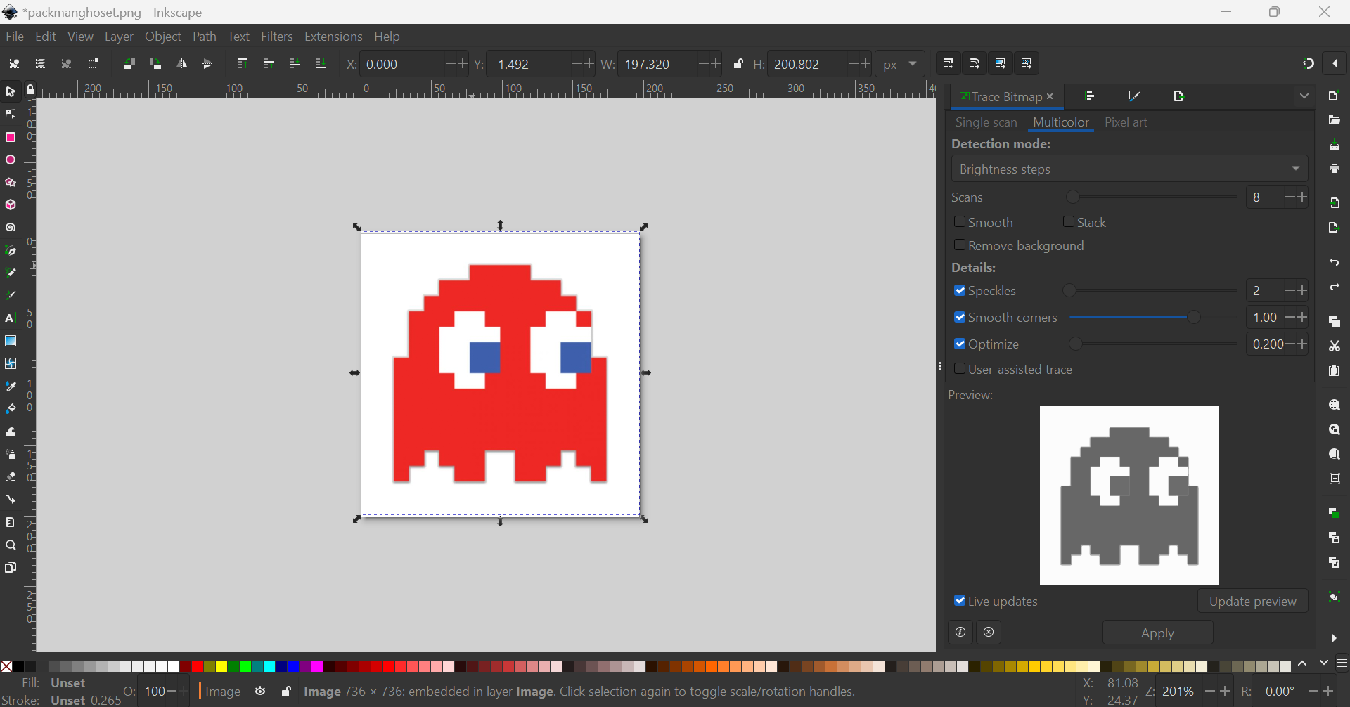
Node Tool to edit the nodes and paths of the vector image to refine the design.Fill and Stroke dialog (Shift + Ctrl + F).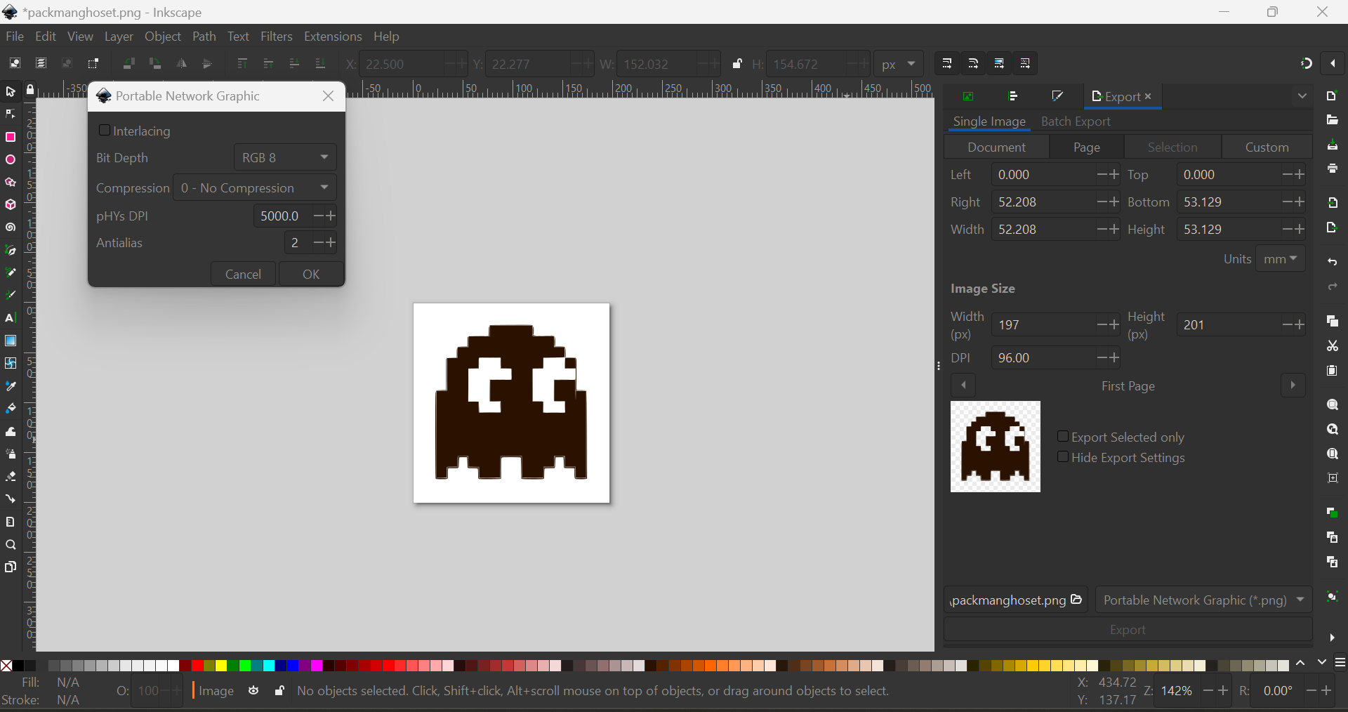
File > Export PNG Image (Shift + Ctrl + E).input format and select SVG.output format and select vinylcutter.load .svg and choose your Pac-Man SVG file.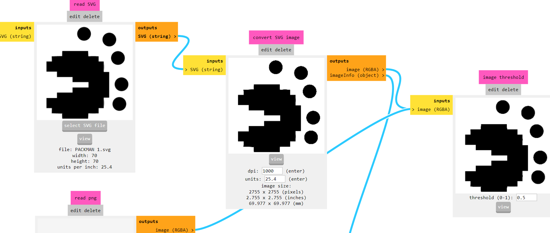
calculate to generate the toolpath for the vinyl cutter.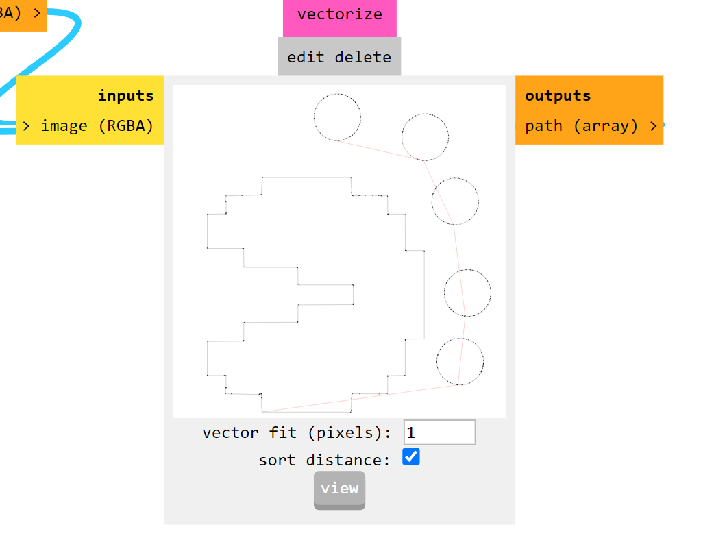
send in FabModules to start the cutting process.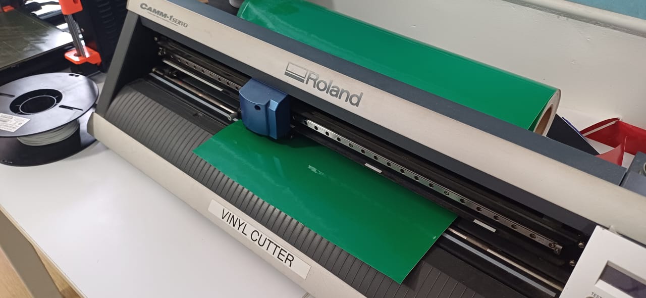
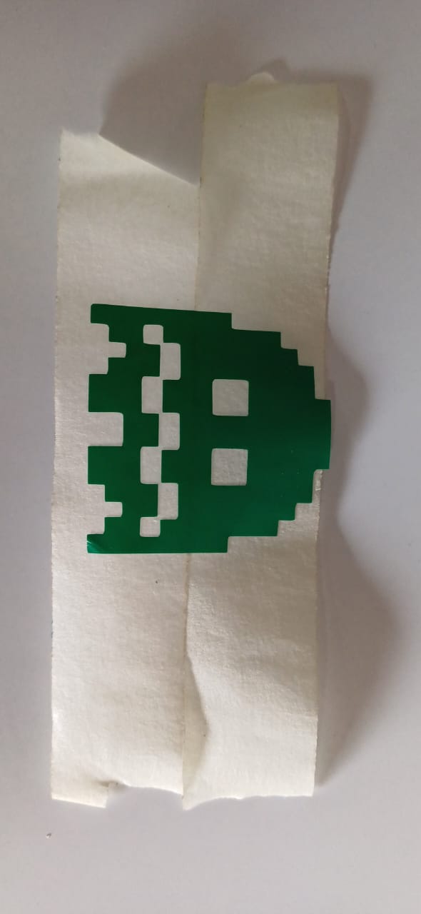
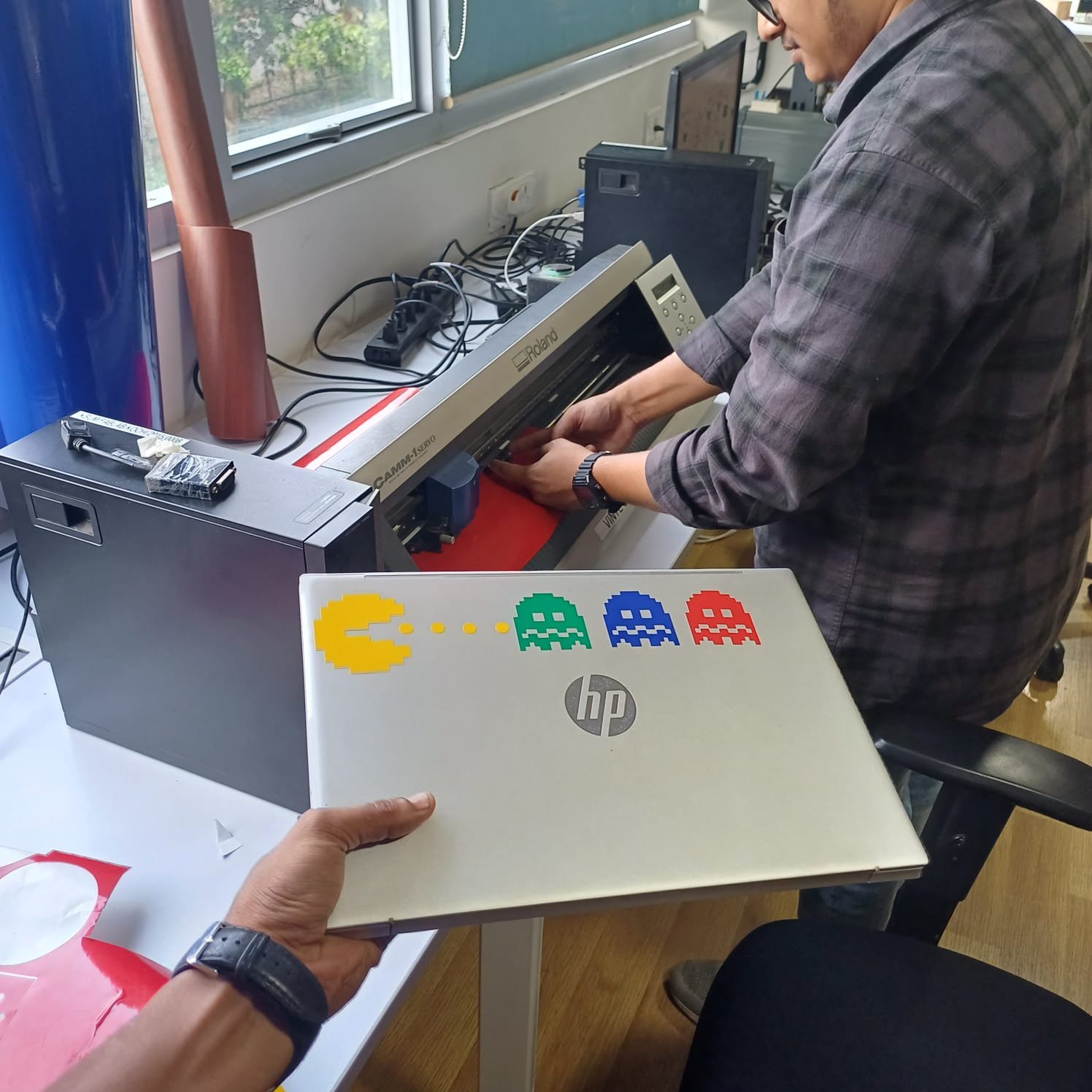
then i simply pealled the sticker out of it using tweezers and used masking tape to trasfer the stiker to my laptop i cut diffrent colors and charecters of packman it was stuck on my laptop
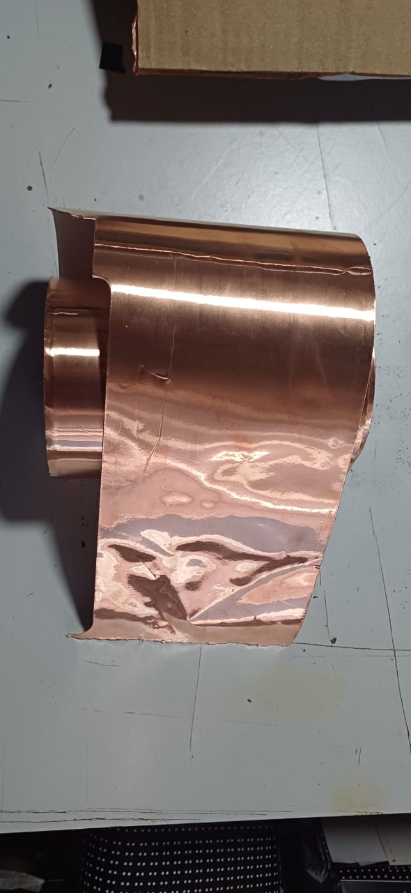
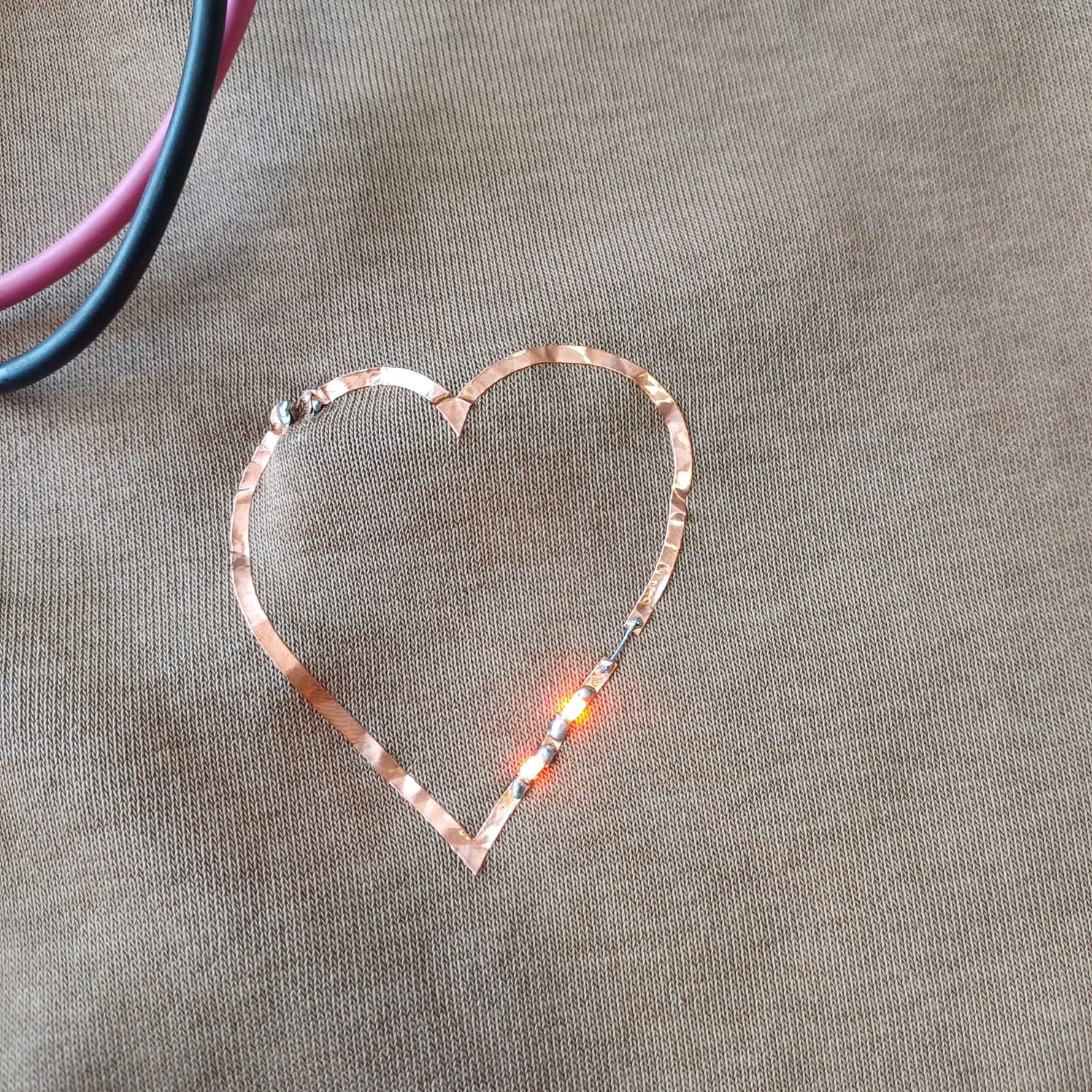
the i moved on to bit of a chalnging task using the copper stiker to make a warable pcb stiker i drew a simple heart shape and made it to attach a 1206 led on it
then using the fab nods send the files to the Roland vinyal cutter and set the knife cutting force to 100gf to get a clean cut, then i carefully moved to stiking it to my fevorite hoddies
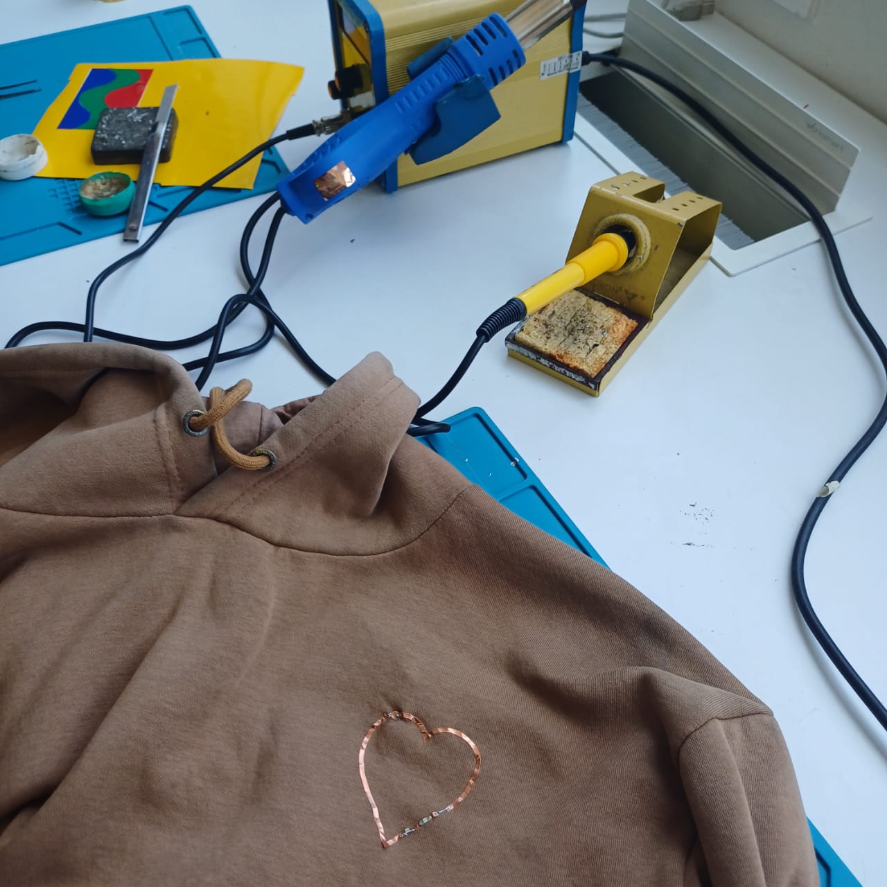
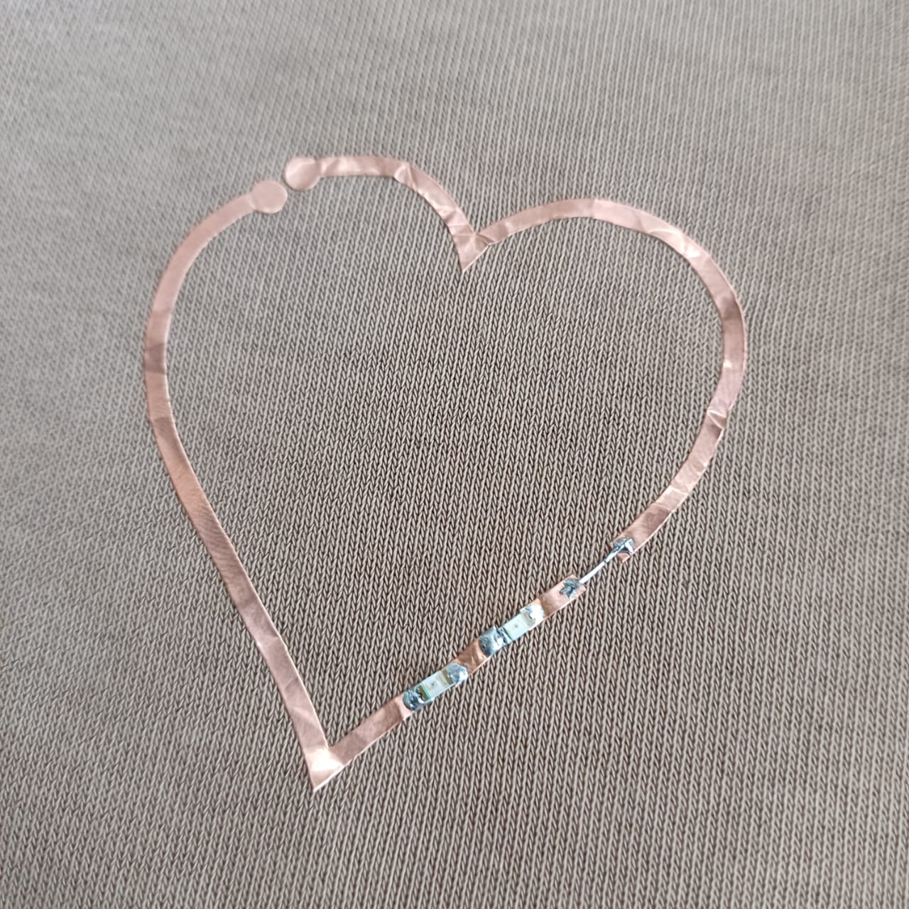
then using the soldering station i solderd 2 1206 package led to the circit and connected it with the powersupply setting the voltage to be 5v volla we have light

So as our second assignment, we were tasked with building a press-fit construction kit. Before diving into the individual projects, we conducted a group assignment to determine the clearances and dimensions needed to achieve a press-fit finger joint.
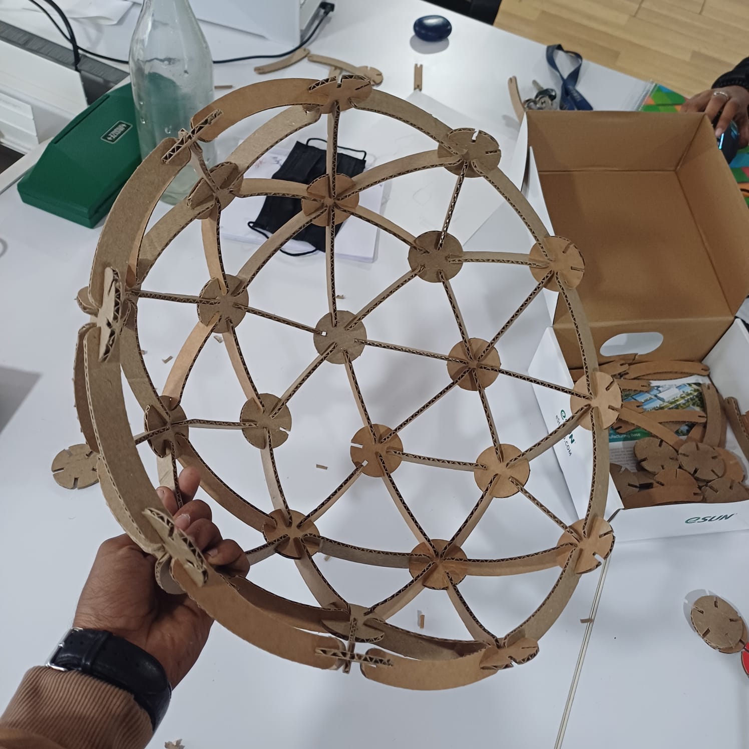
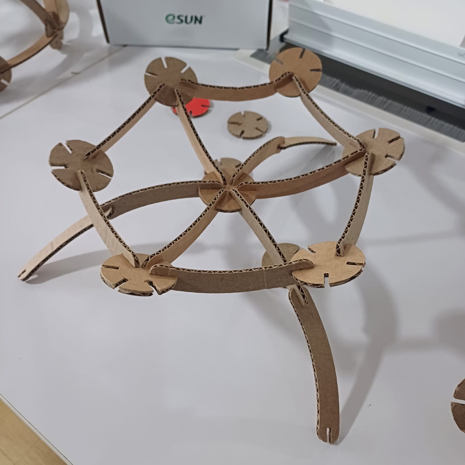
After understanding the necessary clearances, I fired up the Fusion 360 environment to start designing. I decided to create a geodesic dome kit that could be rearranged into various shapes. Using Fusion 360’s parametric design tools, I defined different parameters such as circle diameter, slot size, and slot diameter. These parameters allowed me to maintain consistency throughout the design, even when changing the size of the parts.
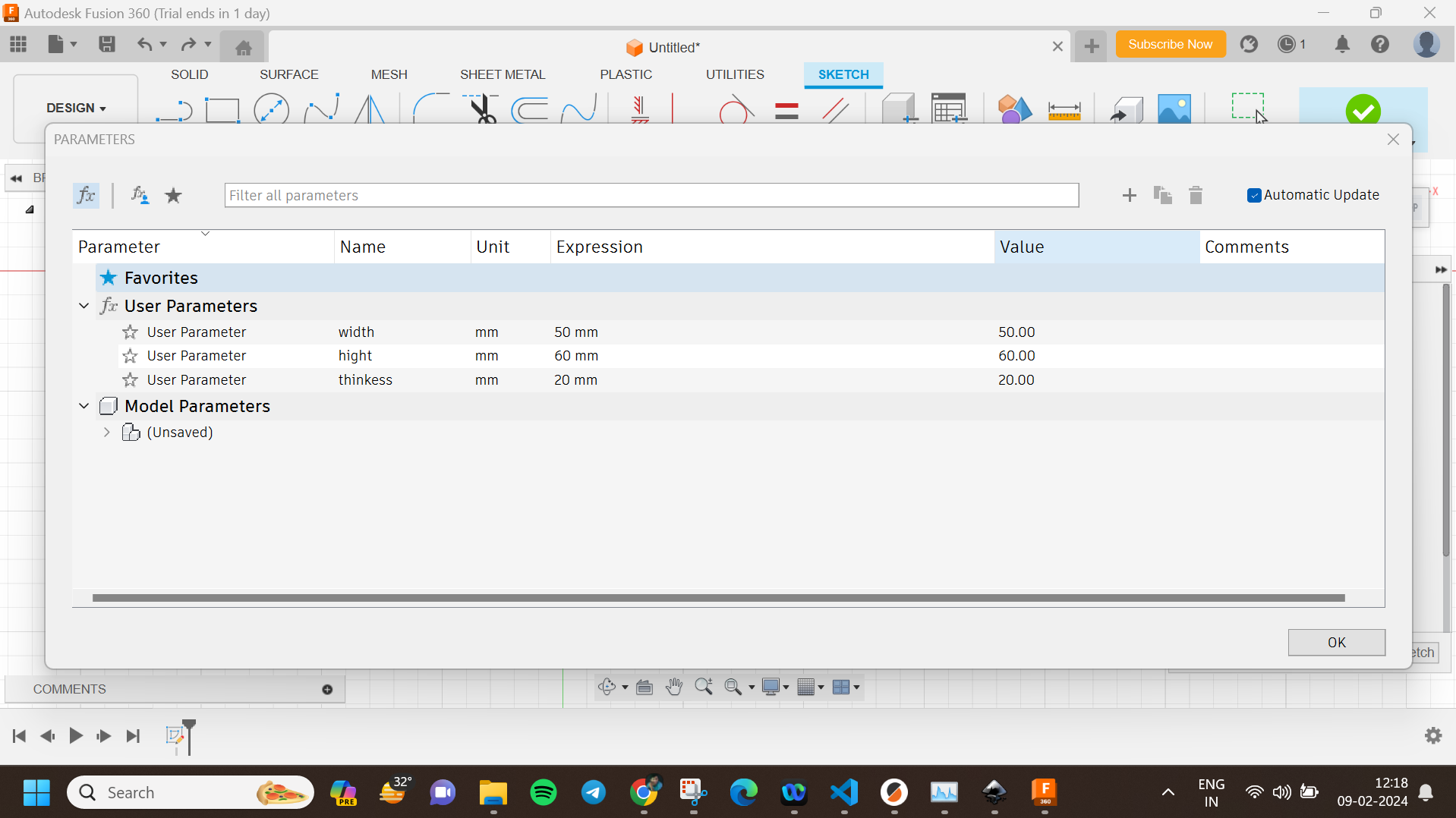
Step 1: Setting Up Parameters
I began by defining key parameters in Fusion 360. This included the circle diameter for the nodes, the slot size for the connecting slots, and the slot diameter. These parameters were set up in the ‘Change Parameters’ window, allowing for easy adjustments. Here are the parameters I used:
Step 2: Creating the Sketch
Next, I created a new sketch and began drawing the basic shapes of the parts. Using the line and circle tools, I sketched the parts with dimensions linked to the parameters I defined earlier. This included the circles for the nodes and the slots for the connections. I used constraints to ensure the design remained symmetrical and aligned.
Step 3: Extruding the Sketch
After finalizing the sketch, I used the extrude tool to convert the 2D sketch into 3D parts. The extrude feature was also parametrically linked to maintain the thickness of the parts consistent across the design. This helped in visualizing the actual 3D shapes and ensuring the slots would fit properly.
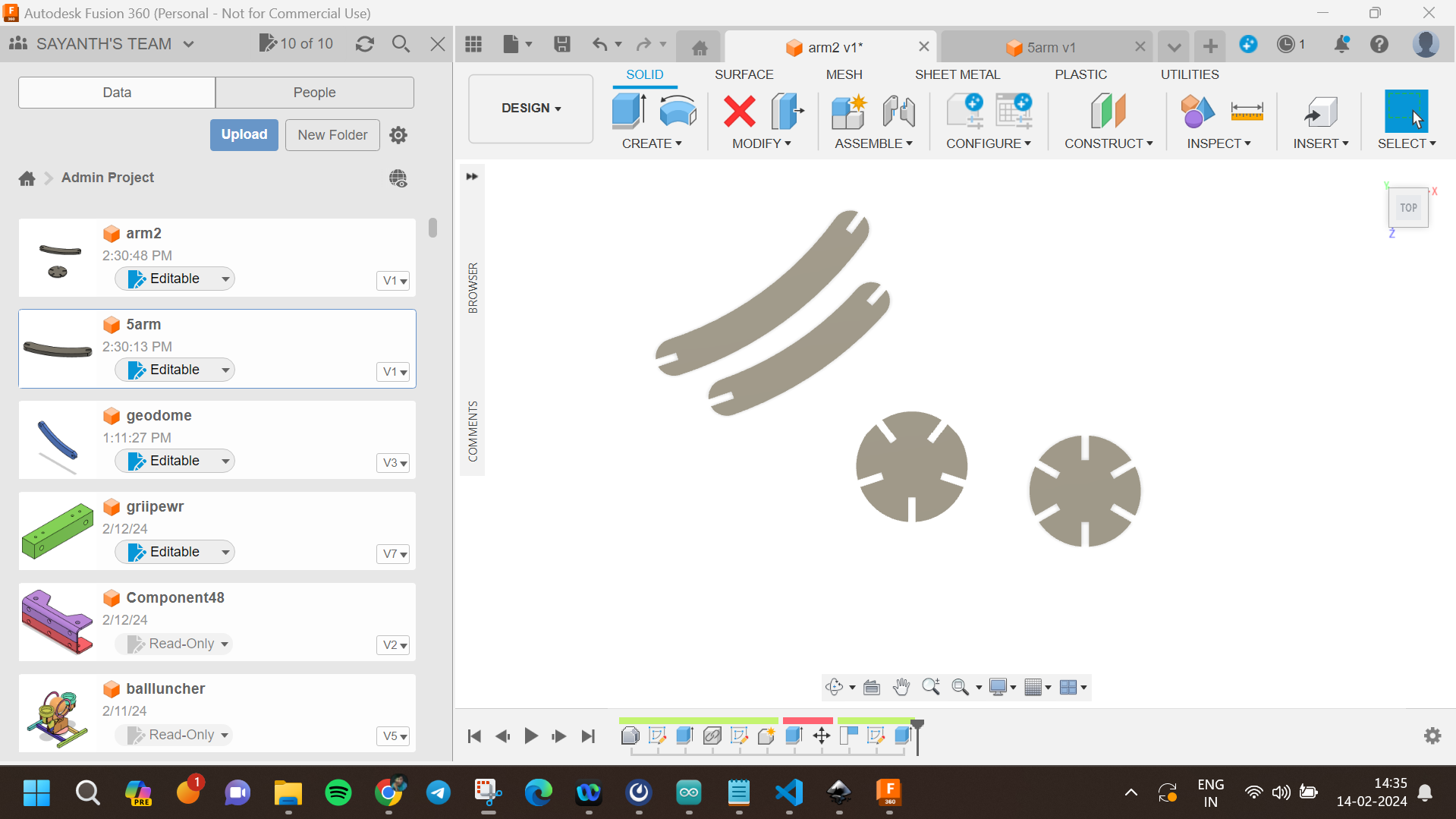
Step 4: Creating the Assembly
Once the parts were extruded, I assembled them virtually to check the fitting. Using the 'Assemble' tool in Fusion 360, I created joints between the parts to ensure they would press-fit together as intended. This step was crucial in identifying any potential fitting issues and making necessary adjustments.
Step 5: Adjusting Parameters
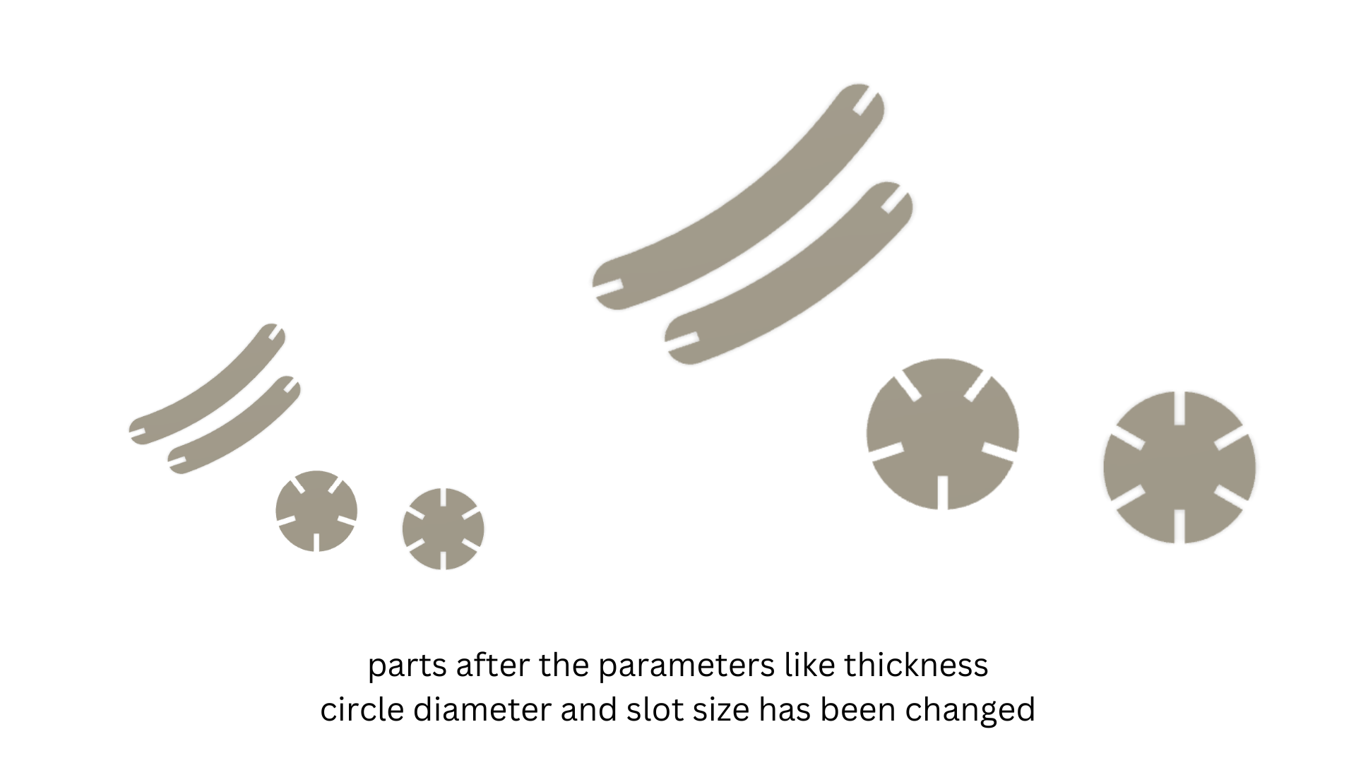
One of the significant advantages of parametric design is the ability to make adjustments easily. I tested different sizes by changing the parameters. For example, increasing the 'CircleDiameter' parameter automatically adjusted all the parts of the design to maintain proportionality. Similarly, changing the 'SlotSize' parameter ensured that all slots were adjusted uniformly, maintaining the press-fit integrity.
During this process, I observed how changes in parameters affected the overall design:
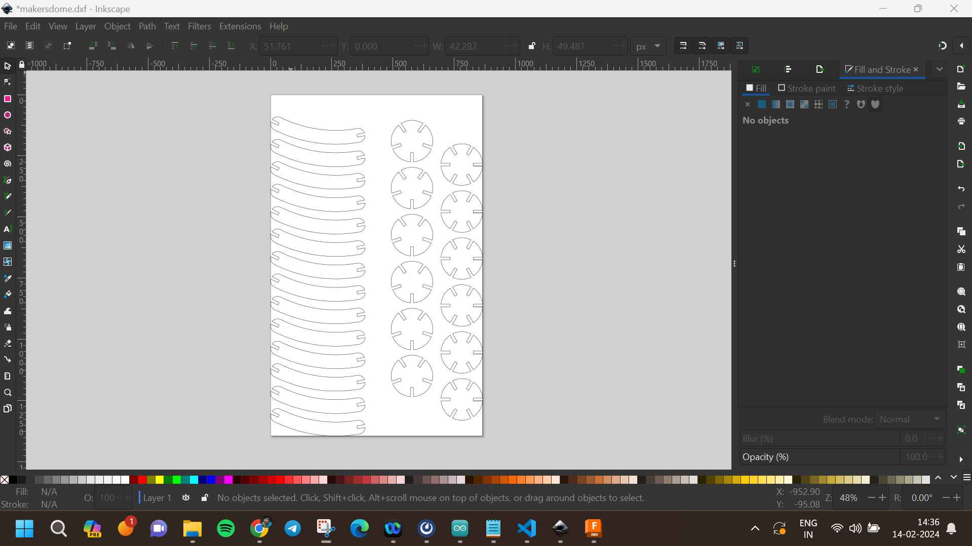
After finalizing the design, I settled on four parts to be cut. I used the projection tool to import the outer sketch of the drawing into Inkscape. In Inkscape, I nested the parts using the align and distribute tool, ensuring minimal material waste and optimal layout for laser cutting. I saved the nested design as a DXF file and transferred it to a flash drive for laser cutting.
With the design ready, I moved on to understanding the laser machines in our lab. Unfortunately, all the machines were either damaged or under maintenance. Despite this, I learned about the basic working principles of laser cutters. To complete the group assignments, we used a laser cutter from a nearby lab, allowing us to cut and assemble our press-fit construction kits.
The ProTech Speedy 400 is a versatile laser cutting and engraving machine known for its precision, speed, and reliability. It is designed for industrial and professional use, offering advanced features to meet various manufacturing and customization needs.
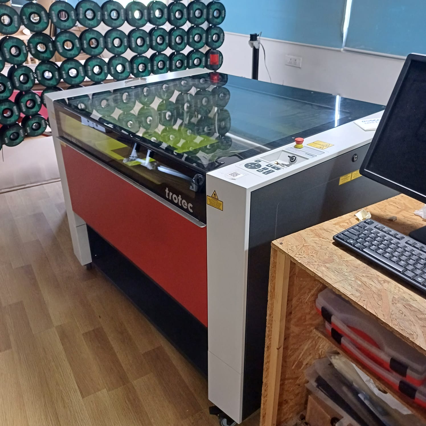
The ProTech Speedy 400 is used in various industries and applications, including:
and then used the control pannal to jog the machine and set the autofocus fuction and also i was introduced to the software as well named trotec job control and did a cut and engarve as a part of the group project sadly the machine was damaged and wasent cutting well so i moveed on to zund cutting machine
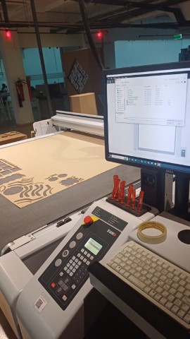
The Zund digital cutter is like a high-tech craft machine. It uses a computer to cut out shapes from different materials like paper, fabric, or plastic with extreme accuracy. It's super precise and fast, making it perfect for industries like packaging and signage. With its easy-to-use software named cut editor and cut queue, we can create intricate designs and turn them into real products in no time.
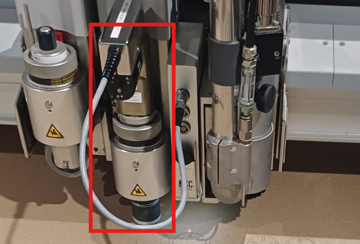
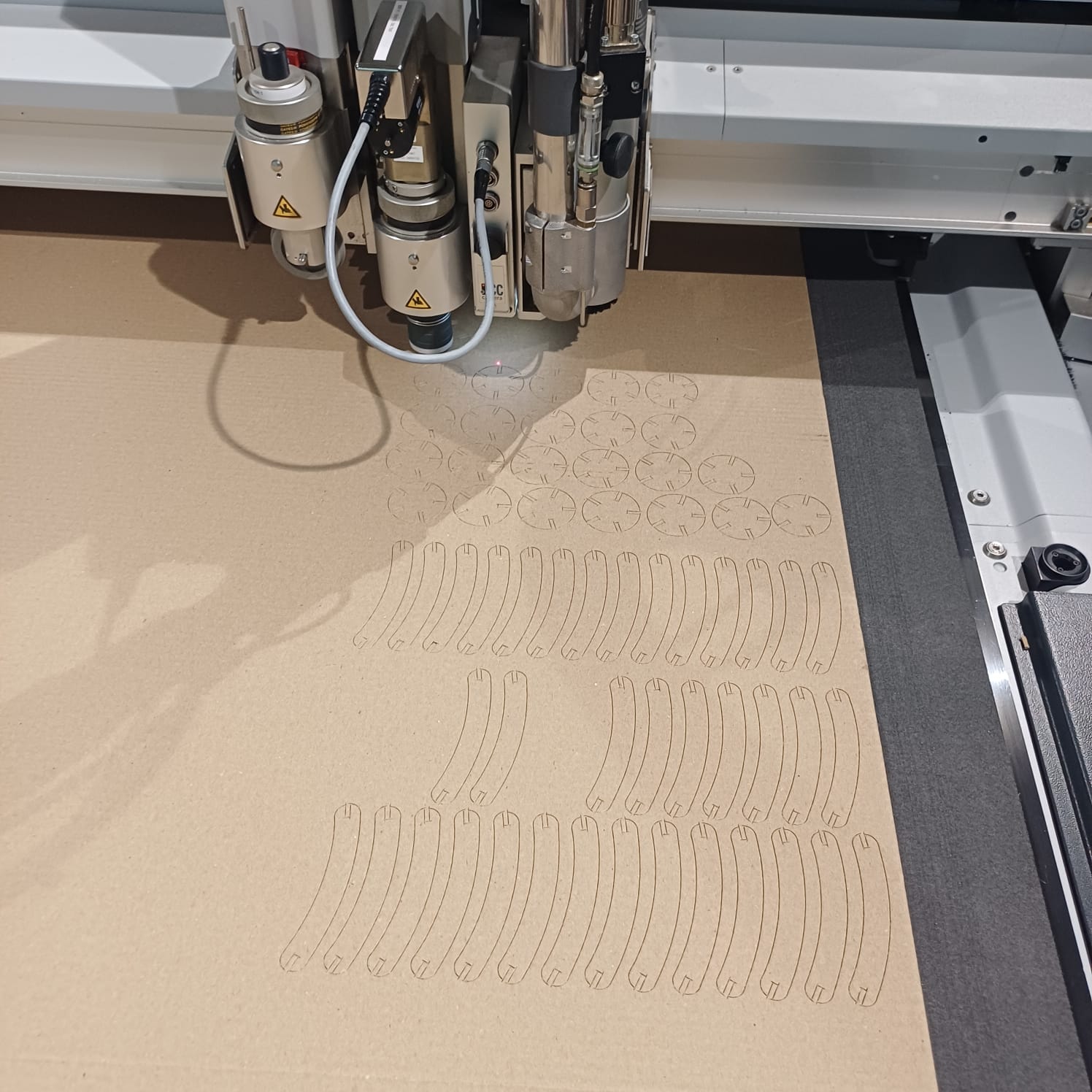
zund has mutliple head that suports multiple machinig oprations and it is a key feture of teh machien and in taht 3 units i uesd teh osilating knife module to cut the cardboard
then i loded the file to zunds computer via flash drive and loded the cut editor sodtware and setup the file setting offsets and doing design corrections
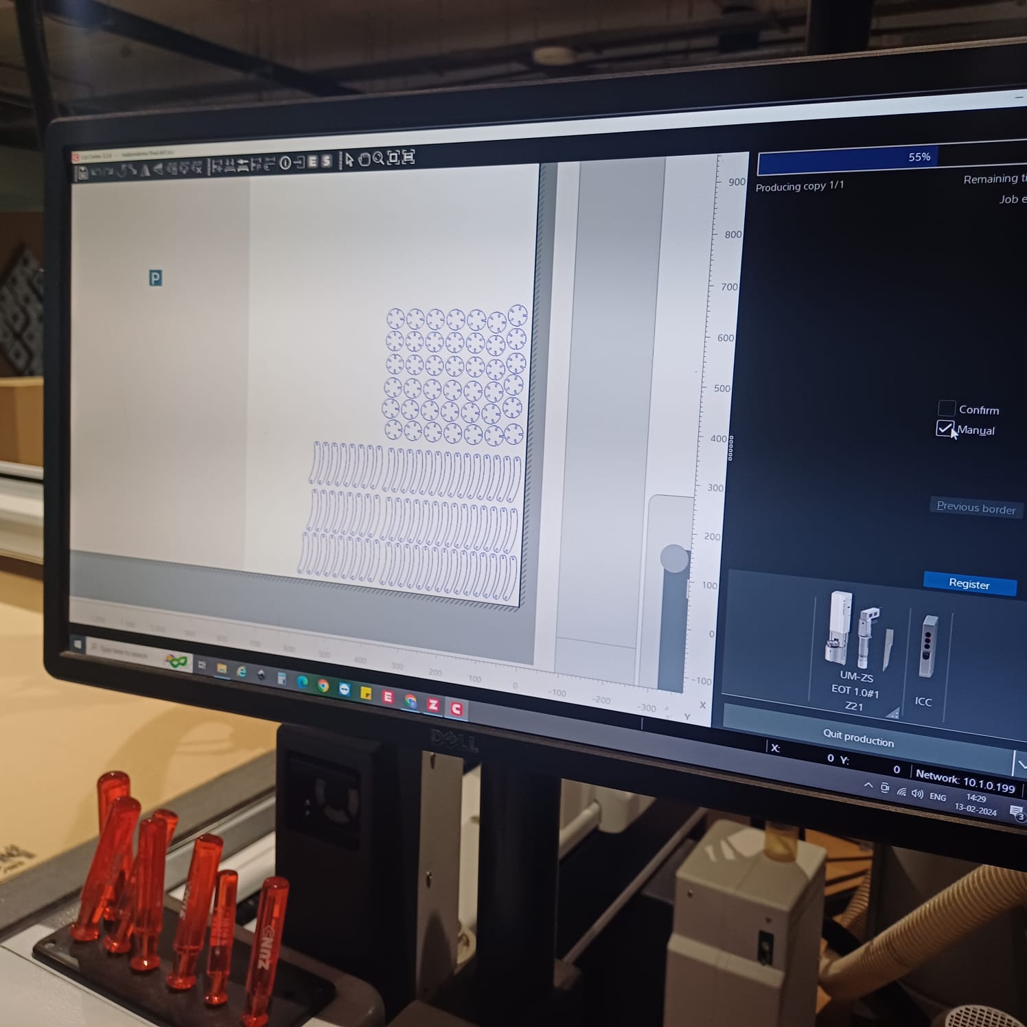
then i send the file to server and loded it on cut queue and set the tool bed offsets and send the file and brought the machine online and set the coreners using manula s well as auto mode to maximise on material used the the zund started cuuting
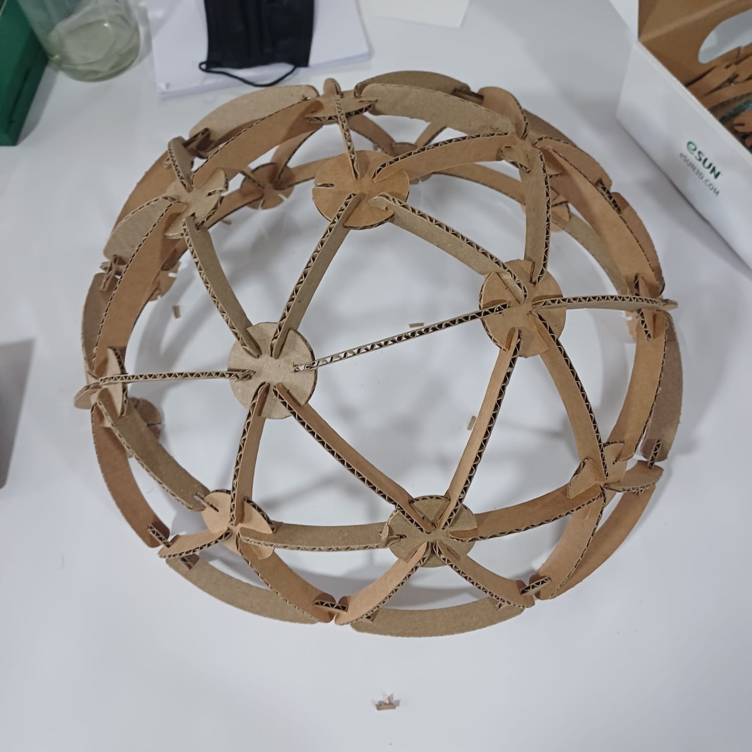
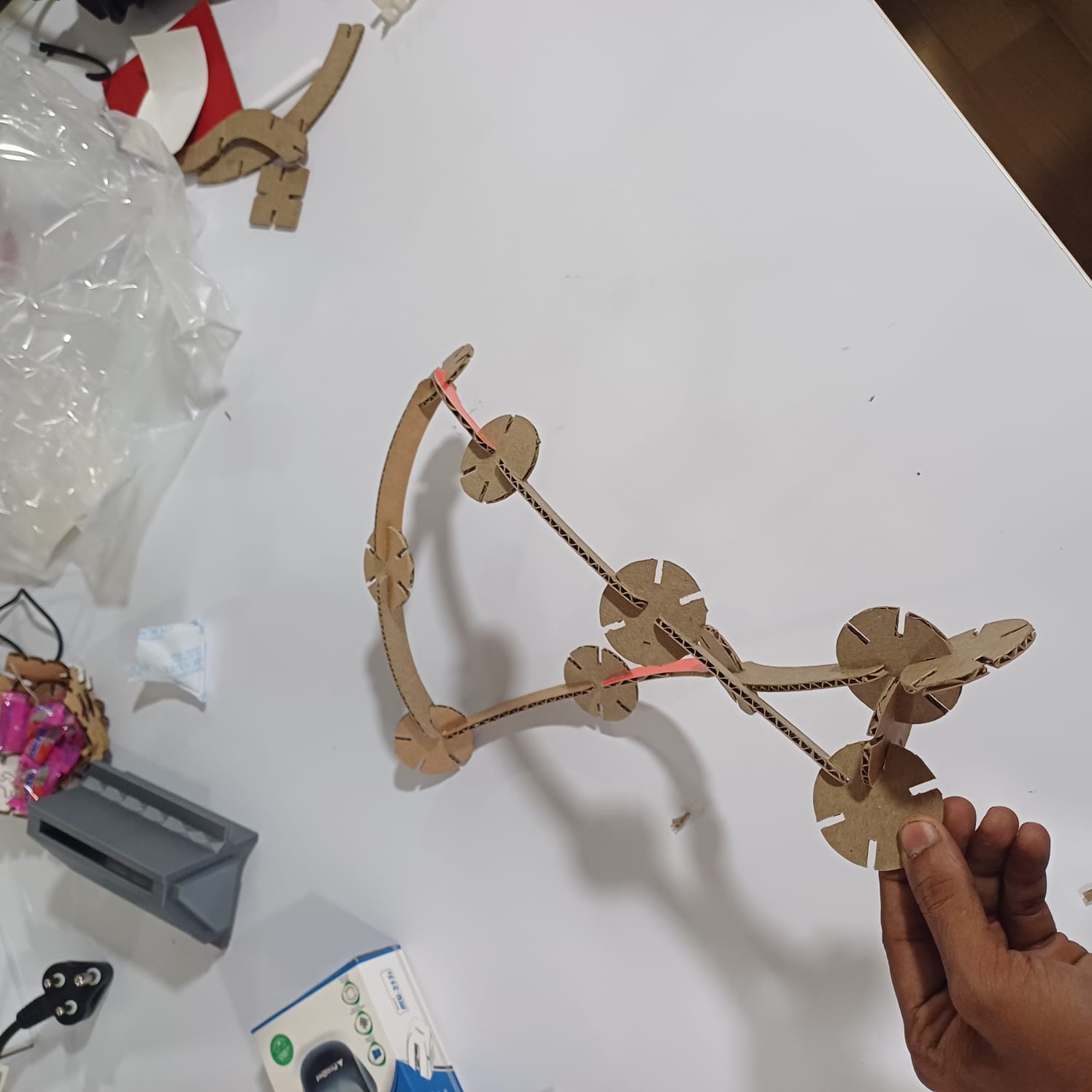
after that i stared assemblying the dome and i did select the dome as a remebrnce to my first startup named MAKERSDOME,onece the dome was finhisned i moved to other shapes as well like a flower holder, and a kind of a dna strcture..
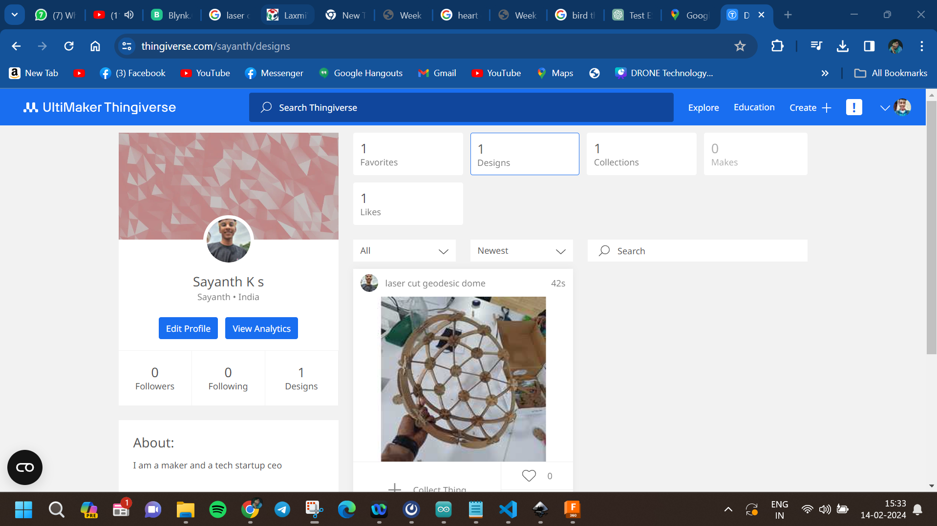
then i uploded the files to my thingiverse page so anyone can try it out