This week, I decided to develop a jumping game using Python and interface it with my hardware. The focus of my project is on application development and interfacing. I plan to create a game where the player can control a character's jumping actions using physical hardware components. This involves integrating input from the hardware into the game's controls, providing a more interactive and immersive experience for the player.
THE IDEA
The concept for my project is to develop a jumping game that utilizes an accelerometer connected to the game via Bluetooth. The accelerometer will detect when the player jumps, and this action will be mirrored in the game, causing the character to jump as well. By integrating hardware and software through Bluetooth communication, the game will offer a dynamic and interactive experience where physical movements directly influence gameplay.
PYTHON
I had some previous experinece in python and using pygame so i used into my advantage in this week here are the few notes about python and using it or devlopeing interfaces
Python is a versatile, high-level programming language known for its readability and simplicity, supporting multiple programming paradigms. Its extensive standard library and active community make it popular for interface development. For graphical user interfaces (GUIs), Python offers Tkinter for small to medium applications, PyQt or PySide for complex desktop applications, and Kivy for multitouch applications across multiple platforms. In web development, Flask is ideal for small to medium applications and APIs, while Django suits large, scalable web applications. Command-line interfaces (CLIs) can be created with argparse or Click, and APIs can be developed using FastAPI or Django REST Framework. Python's ease of learning, rapid development capabilities, extensive libraries, and strong community support make it an excellent choice for developing various types of interfaces, from simple GUIs to complex web applications and APIs.
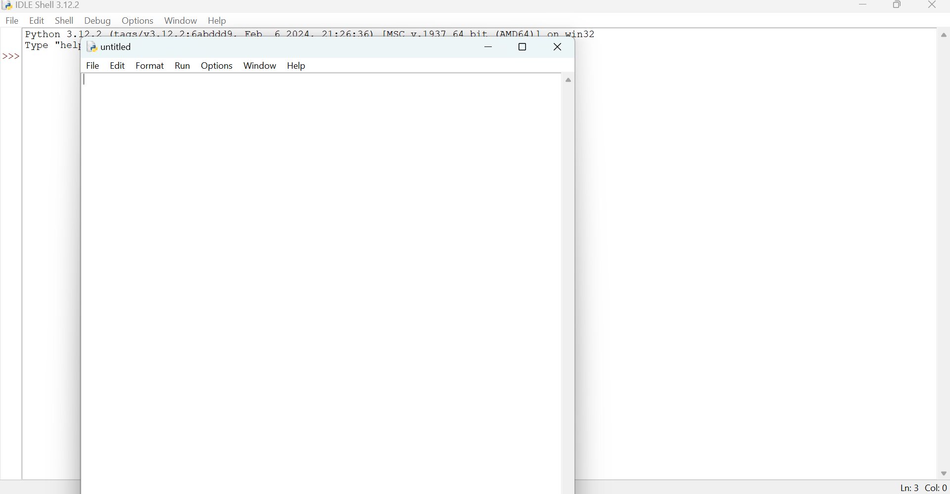
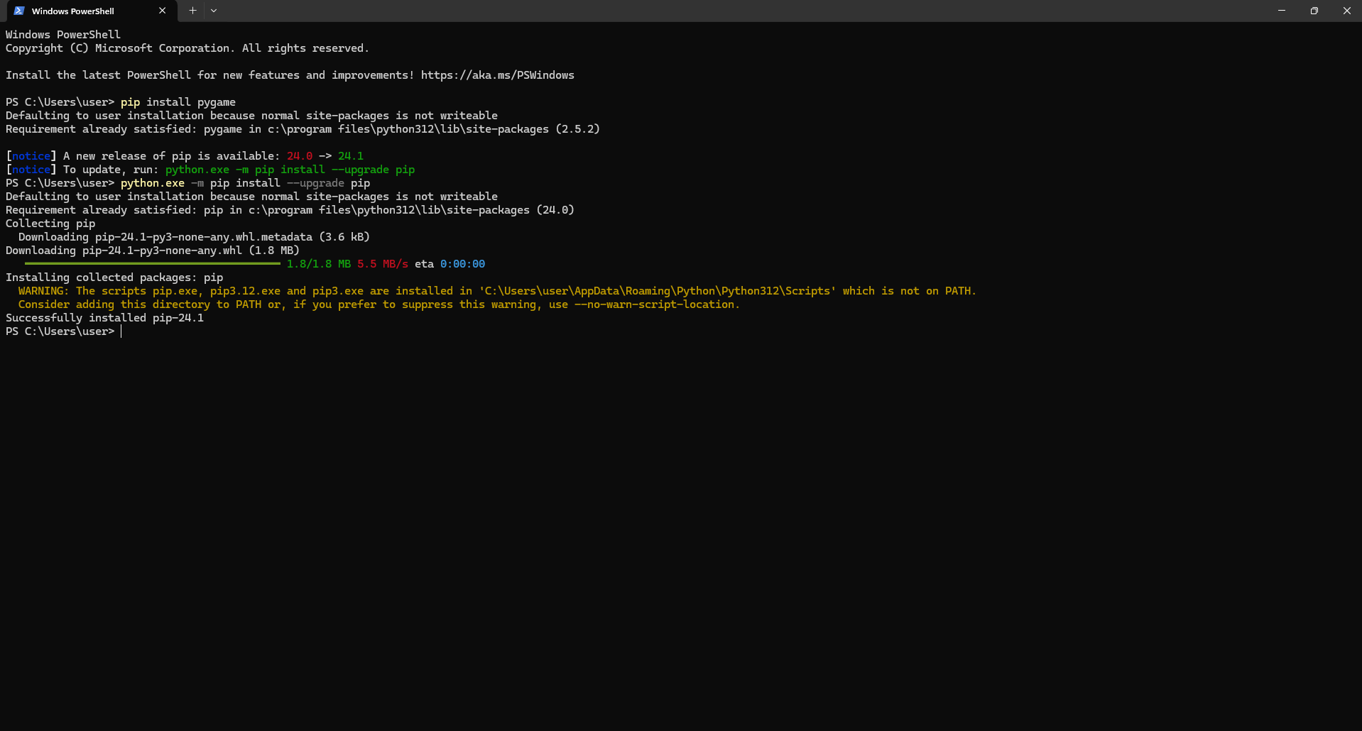
I had python installed in my system i have run teh python version 3.12.2 and i use pip isntallation using termainal to get the nessesry liberies added to python
CREATION OF THE GAME
"Jumping Beans" is an endless runner game where players control a jumping bean character, navigating through a vibrant world filled with obstacles and love signs. The objective is to collect as many love signs as possible while avoiding obstacles to achieve the highest score. Players can make the bean jump by pressing the spacebar, timing their jumps to avoid obstacles and collect love signs strategically. As players progress, the game becomes progressively challenging with faster obstacles and more intricate patterns. When the player collides with an obstacle, the game ends, and they have the option to restart and try again.
Pygame Overview
Pygame is a cross-platform set of Python modules designed for creating video games. It provides functionality for handling various aspects of game development such as graphics, sound, input handling, and more. Here's an overview of Pygame and its key features:
Graphics: Pygame provides tools for drawing shapes, images, and text on the screen. Developers can create visually appealing games by manipulating pixels, drawing primitives, loading and displaying images, and rendering fonts.
Sound and Music: With Pygame, developers can incorporate sound effects and music into their games. It supports various audio formats and provides functions for playing, pausing, stopping, and controlling the volume of sound elements.
Input Handling: Pygame allows developers to handle user input such as keyboard, mouse, and joystick events. This enables game interactivity by responding to player actions like key presses, mouse clicks, and joystick movements.
Game Physics: Although Pygame doesn't have built-in physics engines, developers can implement basic physics simulations for game elements like gravity, collision detection, and object movement using Pygame's built-in functions and mathematical operations.
Game Loop: Pygame operates within a main game loop, where the game continuously updates its state, processes user input, and renders graphics. This loop ensures smooth and consistent gameplay by maintaining a consistent frame rate.
Cross-Platform: Pygame is compatible with multiple platforms, including Windows, macOS, and Linux, making it accessible to a wide range of developers.
Community and Documentation: Pygame has an active community of developers who contribute tutorials, examples, and support to help others learn and develop games. The official Pygame documentation provides detailed explanations of Pygame's functions and modules, making it easy for developers to get started.
Open Source: Pygame is an open-source project, allowing developers to access and modify its source code freely. This fosters innovation and collaboration within the community, enabling developers to create diverse and unique games.
Jumping Beans Game Plan
Initialize Pygame and Set Screen Dimensions:
Start by importing the Pygame library and initializing it.
Define the screen width and height.
Define Colors:
Define colors that will be used in the game.
Player Variables:
Set up variables for the player, such as its radius, initial position, speed, and jump properties.
Obstacle Variables:
Define variables related to obstacles, including their radius and speed.
Love Sign Variables:
Set up variables for love signs, including their radius and speed.
Lists for Obstacles and Love Signs:
Create empty lists to hold instances of obstacles and love signs.
Load Music and Sound Effects:
Load the music for the game, as well as sound effects for jumping, collecting love signs, and game over.
Initialize the Screen:
Set up the game window and its caption.
Define Functions:
create_obstacle(): Creates a new obstacle and adds it to the list.
create_love(): Creates a new love sign and adds it to the list.
reset_game(): Resets all game variables to their initial values.
Main Game Loop:
Start the main game loop, which will continue until the player quits the game.
Event Handling:
Handle user events, such as quitting the game or pressing keys for jumping and restarting.
Game Logic:
Apply gravity to the player.
Move the player and handle jumping.
Move obstacles and check for collisions with the player.
Move love signs and check for collisions with the player.
Create new obstacles and love signs with certain probabilities.
Update the screen with the player, obstacles, love signs, and score.
Display Game Over Screen:
When the game is over, display the "Game Over" text and instructions to restart.
Quit Pygame and Exit:
Properly quit Pygame and exit the program.
Jumping Beans Code Breakdown
1. Importing Libraries
import pygame
import sys
import random
2. Initializing Pygame
pygame.init()
3. Screen Dimensions and Colors
SCREEN_WIDTH = 1200
SCREEN_HEIGHT = 600

WHITE = (255, 255, 255)
BLACK = (0, 0, 0)
RED = (255, 102, 102)
GREEN = (102, 204, 102)
BLUE = (102, 178, 255)
4. Player and Object Variables
These variables define the properties of the player, obstacles, and love signs.
running: Indicates if the game is running.
game_over: Indicates if the game is over.
score: Stores the player's score.
loading_progress: Tracks loading progress (unused).
9. Event Handling
Handles quitting the game and restarting.
10. Game Logic
Applies gravity to the player.
Checks for player collision with obstacles and love signs.
Updates player and object positions.
Generates new obstacles and love signs randomly.
11. Drawing
Clears the screen.
Draws the player, obstacles, love signs, and score.
Updates the display.
12. Game Over Screen
Displays "Game Over" message and instructions to restart.
13. Quit Pygame
pygame.quit()
sys.exit()
PYTHON CODE
import pygame
import sys
import random
# Initialize Pygame
pygame.init()
# Screen dimensions
SCREEN_WIDTH = 1200
SCREEN_HEIGHT = 600
# Colors
WHITE = (255, 255, 255)
BLACK = (0, 0, 0)
RED = (255, 102, 102) # Light Red
GREEN = (102, 204, 102) # Light Green
BLUE = (102, 178, 255) # Light Blue
# Player variables
player_radius = 25
player_x = 50
player_y = SCREEN_HEIGHT - player_radius * 2
player_y_speed = 0
gravity = 1
jump_force = -15
max_jump_count = 2
jump_count = 0
is_jumping = False
# Obstacle variables
obstacle_radius = 15
obstacle_speed = 5
# Love sign variables
love_radius = 15
love_speed = 3
# List to hold the obstacles and love signs
obstacles = []
loves = []
# Load music
pygame.mixer.music.load('jump_sound.wav') # Jump sound
collect_sound = pygame.mixer.Sound('collect_sound.wav') # Love sign collect sound
game_over_sound = pygame.mixer.Sound('game_over_sound.wav') # Game over sound
# Initialize the screen
screen = pygame.display.set_mode((SCREEN_WIDTH, SCREEN_HEIGHT))
pygame.display.set_caption("Jumping Beans")
clock = pygame.time.Clock()
# Function to create a new obstacle
def create_obstacle():
obstacle_x = SCREEN_WIDTH
obstacle_y = SCREEN_HEIGHT - obstacle_radius * 2
obstacles.append(pygame.Rect(obstacle_x, obstacle_y, obstacle_radius * 2, obstacle_radius * 2))
# Function to create a new love sign
def create_love():
love_x = SCREEN_WIDTH + love_radius * 2 # Start from the right side of the screen
love_y = random.randint(0, SCREEN_HEIGHT - love_radius * 2)
loves.append(pygame.Rect(love_x, love_y, love_radius * 2, love_radius * 2))
# Function to reset the game
def reset_game():
global player_y, player_y_speed, obstacles, loves, game_over, jump_count, score
player_y = SCREEN_HEIGHT - player_radius * 2
player_y_speed = 0
obstacles = []
loves = []
game_over = False
jump_count = 0
score = 0
# Main game loop
running = True
game_over = False
score = 0
loading_progress = 0
while running:
for event in pygame.event.get():
if event.type == pygame.QUIT:
running = False
elif event.type == pygame.KEYDOWN:
if event.key == pygame.K_SPACE and not game_over:
if jump_count < max_jump_count:
player_y_speed = jump_force * 1.5
jump_count += 1
pygame.mixer.music.play() # Play jump sound
if not is_jumping:
is_jumping = True
player_y_speed = jump_force
elif event.key == pygame.K_r and game_over:
reset_game()
if not game_over:
# Apply gravity
player_y_speed += gravity
player_y += player_y_speed
# Check if the player is on the ground
if player_y >= SCREEN_HEIGHT - player_radius * 2:
player_y = SCREEN_HEIGHT - player_radius * 2
player_y_speed = 0
is_jumping = False
jump_count = 0
# Move the obstacles
for obstacle in obstacles:
obstacle.x -= obstacle_speed
# Check collision with player
if obstacle.colliderect(pygame.Rect(player_x, player_y, player_radius * 2, player_radius * 2)):
game_over = True
game_over_sound.play() # Play game over sound
# If obstacle moves off the screen, remove it
if obstacle.right < 0:
obstacles.remove(obstacle)
# Move the love signs
for love in loves:
love.x -= love_speed
# Check collision with player
if love.colliderect(pygame.Rect(player_x, player_y, player_radius * 2, player_radius * 2)):
score += 1
loves.remove(love)
collect_sound.play() # Play love sign collect sound
# If love sign moves off the screen, remove it
if love.right < 0:
loves.remove(love)
# Create new obstacles and love signs
if random.randint(0, 200) < 1:
create_obstacle()
if random.randint(0, 100) == 0:
create_love()
# Clear the screen
screen.fill(WHITE)
# Draw the player
pygame.draw.circle(screen, GREEN, (player_x + player_radius, player_y + player_radius), player_radius)
# Draw the obstacles
for obstacle in obstacles:
pygame.draw.circle(screen, RED, obstacle.center, obstacle_radius)
# Draw the love signs
for love in loves:
pygame.draw.circle(screen, BLUE, love.center, love_radius)
# Display score
font = pygame.font.SysFont(None, 24)
score_text = font.render("Score: " + str(score), True, BLACK)
screen.blit(score_text, (10, 10))
# Update the display
pygame.display.update()
# Cap the frame rate
clock.tick(30)
else:
# Game over screen
screen.fill(WHITE)
font = pygame.font.SysFont(None, 50)
text = font.render("Game Over", True, BLACK)
text_rect = text.get_rect(center=(SCREEN_WIDTH // 2, SCREEN_HEIGHT // 2 - 50)) # Center vertically and horizontally
screen.blit(text, text_rect)
restart_text = font.render("Press 'R' to restart", True, BLACK)
restart_text_rect = restart_text.get_rect(center=(SCREEN_WIDTH // 2, SCREEN_HEIGHT // 2 + 50)) # Center vertically and horizontally
screen.blit(restart_text, restart_text_rect)
pygame.display.update()
pygame.quit()
sys.exit()
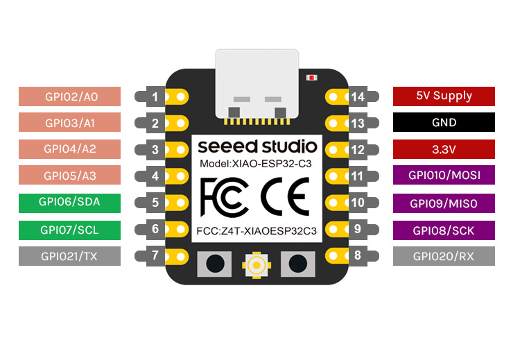
XIAO ESP32 C3
The Xiao ESP32-C3 is a compact and powerful microcontroller board based on the ESP32-C3 chip. It features a 32-bit RISC-V core with Wi-Fi and Bluetooth capabilities. With its small form factor and low power consumption, it's well-suited for embedded projects where space and energy efficiency are crucial. The board provides GPIO pins for interfacing with external components, making it ideal for sensor integration and control applications. Additionally, its support for Bluetooth Low Energy enables easy communication with other devices, such as smartphones or PCs. Overall, the Xiao ESP32-C3 offers a versatile platform for developing projects that require wireless connectivity and sensor interaction.
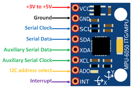
MPU6050
The MPU6050 is a popular accelerometer and gyroscope sensor module often used in motion sensing applications. It features a 3-axis accelerometer and a 3-axis gyroscope, allowing it to measure acceleration and rotation in three dimensions.
The MPU6050 communicates with microcontrollers via I2C (Inter-Integrated Circuit) protocol, making it easy to interface with various development boards like the Xiao ESP32-C3. By reading the sensor's data, you can detect changes in orientation, tilt, and motion.
For the jumping game project, the MPU6050 will be used to detect the player's jumps by monitoring changes in acceleration. When the player jumps, the accelerometer will register the sudden upward acceleration, which will be interpreted by the microcontroller (Xiao ESP32-C3) to trigger the character's jump in the game.
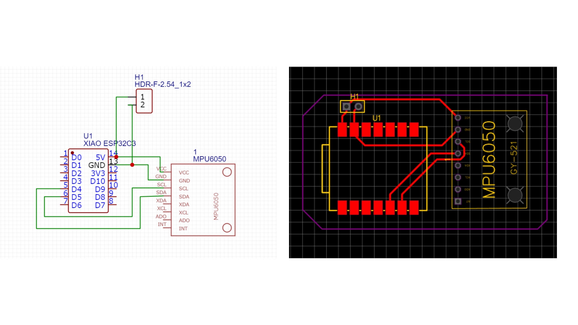
Designing PCB for ESP-NOW Communication using EasyEDA
Circuit Design
For your jumping game project, you can design a simple PCB using EasyEDA to connect the Xiao ESP32-C3 and the MPU6050 sensor. Here's a basic circuit design:
Xiao ESP32-C3:
Connect the power and ground pins of the Xiao ESP32-C3 to the corresponding power and ground rails on the PCB.
Connect the I2C pins (SCL and SDA) of the Xiao ESP32-C3 to the corresponding pins of the MPU6050 sensor.
Add decoupling capacitors (100nF) between the power and ground pins of the ESP32-C3.
MPU6050 Sensor:
Connect the VCC pin of the MPU6050 to the 3.3V power rail.
Connect the GND pin of the MPU6050 to the ground rail.
Connect the SCL pin of the MPU6050 to the ESP32-C3's SCL pin.
Connect the SDA pin of the MPU6050 to the ESP32-C3's SDA pin.
Add pull-up resistors (4.7kΩ) between the SCL and SDA pins of the MPU6050 and the 3.3V power rail.
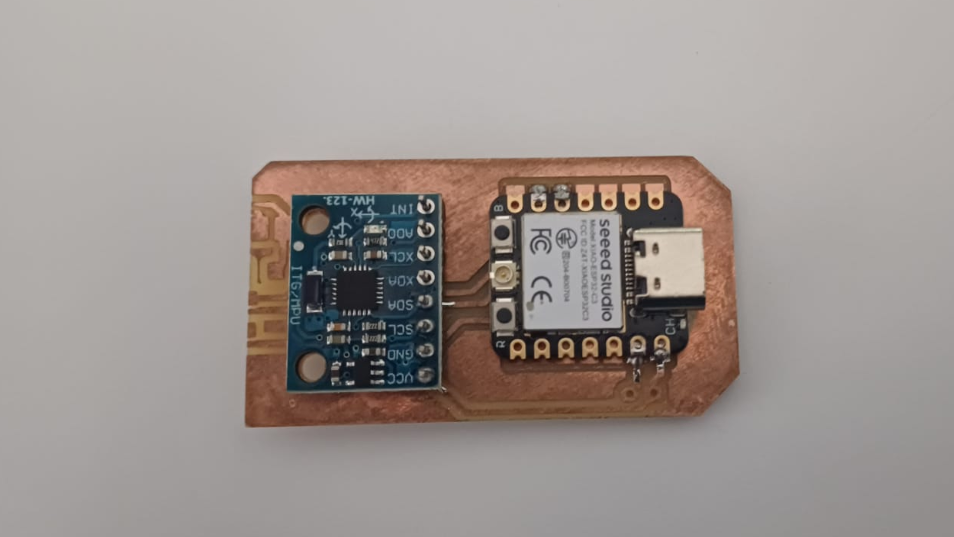
PRODUCTION
After designing the PCB layouts for the project using EasyEDA, I exported the Gerber files and converted them into PNG images of the pads, traces, and drill holes using our lab's Gerber to PNG converter tool. These images were essential for visualizing the PCB design before manufacturing. Then, following the fabrication methods discussed during the Embedded Production Week, I used the PNG files to mill my PCB on the Modela milling machine. This fabrication process allowed me to create precise and customized PCBs for my project.
ASSEMBLY
After finalizing the PCB designs, I generated a Bill of Materials (BOM) using EasyEDA's built-in BOM generator. This BOM listed all the components needed for the project. Next, I requested the components using the Fab Stash, our lab's inventory management app, ensuring I had all the necessary parts for assembly.
With the components in hand, I proceeded to solder the two PCBs together. Following the soldering process, I verified the connections and tested the functionality This involved checking for proper signal transmission between the sender and receiver devices and ensuring that the LEDs responded accordingly to the transmitted data. Through careful
you can refference week9 to get more info on how to oused EASY EDA to create the PCB
XIAO ESP32C3 CODE
Libraries:
BleKeyboard: Library for emulating a Bluetooth keyboard.
Adafruit_MPU6050 and Adafruit_Sensor: Libraries for interfacing with MPU6050 accelerometer and gyroscope sensor.
Wire: I2C communication library.
Initialization:
BleKeyboard bleKeyboard: Object for Bluetooth keyboard emulation.
Adafruit_MPU6050 mpu: Object for MPU6050 sensor.
Serial.begin(115200): Initializes serial communication for debugging.
bleKeyboard.begin(): Initializes Bluetooth keyboard.
Setup Function:
Initializes serial communication and BLE keyboard.
Initializes MPU6050 sensor and sets its accelerometer range to 8G.
Loop Function:
Continuously reads accelerometer data from the MPU6050 sensor.
Checks the Z-axis acceleration value.
If the Z acceleration is above 1 m/s^2, it means a jump is detected.
It sends a space key press to the BLE keyboard using bleKeyboard.print(" ").
After a small delay (delay(10)), it releases all keys using bleKeyboard.releaseAll().
Output:
The Z-axis acceleration value is printed to the serial monitor.
If a jump is detected, "Jump detected" message is printed to the serial monitor.
Functionality:
The system interprets a jump detected by the MPU6050 sensor as a space bar press, effectively emulating a space key press on a Bluetooth keyboard.
CODE
            #include
                #include
                #include
                #include

                // Initialize Bluetooth keyboard and MPU6050 sensor objects
                BleKeyboard bleKeyboard;
                Adafruit_MPU6050 mpu;

                void setup() {
                  Serial.begin(115200);  // Start serial communication
                  Serial.println("Starting BLE work!");
                  bleKeyboard.begin();   // Initialize BLE keyboard

                  // Initialize MPU6050 sensor
                  if (!mpu.begin()) {    // Check if sensor initialization fails
                    Serial.println("Failed to find MPU6050 chip");
                    while (1) {
                      delay(10);
                    }
                  }
                  Serial.println("MPU6050 Found!");
                  mpu.setAccelerometerRange(MPU6050_RANGE_8_G);  // Set accelerometer range to 8G
                }

                void loop() {
                  // Get new sensor events with the readings
                  sensors_event_t a, g, temp;
                  mpu.getEvent(&a, &g, &temp);

                  // Print out the Z acceleration value
                  Serial.print("Acceleration Z: ");
                  Serial.print(a.acceleration.z);
                  Serial.println(" m/s^2");

                  // Check if Z acceleration is above 1 m/s^2
                  if (a.acceleration.z > 1) {
                    Serial.println("Jump detected");

                    // Press the space key
                    bleKeyboard.print(" ");
                    delay(10);  // Adjust if necessary
                    bleKeyboard.releaseAll();
                  }

                  delay(100);  // Delay to prevent rapid detection
                }
.png)