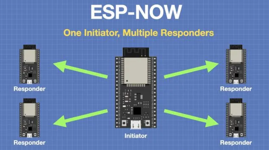
In this project, an ESP8266 development board acts as the master controller, communicating with two ESP-WROOM-02D modules configured as secondery nodes. The goal is to establish a wireless communication network using the ESP-NOW protocol, enabling remote control of devices connected to each ESP-WROOM-02D module. This project is intented for efficient and direct communication between the master and secondery nodes without the need for a traditional Wi-Fi network infrastructure. By leveraging ESP-NOW, the project achieves low-latency and reliable data transmission, making it suitable for applications requiring decentralized control or point-to-point communication scenarios.
In this project, an ESP8266 development board acts as the master controller, communicating wirelessly with two ESP8266 modules configured as secondary nodes. Each secondary node controls an LED. The master ESP8266 can remotely toggle these LEDs on or off based on commands transmitted over Wi-Fi using the ESP-NOW protocol.
i used the following documentations as references for ESPNOW
Each device participating in the ESP-NOW network needs to be initialized with the ESP-NOW protocol. One device typically acts as a sender (transmitter), while the other acts as a receiver. However, devices can also operate in both roles.
Devices need to register their MAC addresses with each other to establish a communication link. Once registered, devices can communicate directly without needing to know each other's IP addresses.
The sender prepares data to be transmitted, which can be in the form of packets. ESP-NOW supports both unicast (point-to-point) and broadcast communication. For unicast communication, the sender specifies the MAC address of the receiver. For broadcast, it sends data to a predefined broadcast MAC address.
The sender transmits data packets over the air using the ESP-NOW protocol. The receiver, listening for ESP-NOW packets, captures and processes the incoming data.
The receiver receives the data packets and processes the information contained within them. It can then perform actions based on the received data, such as displaying temperature and humidity readings on the OLED display.
ESP-NOW does not provide built-in acknowledgment of received packets. However, the application can implement its own acknowledgment mechanism if required.
ESP-NOW does not include error correction or retransmission mechanisms. Applications may need to handle packet loss or errors at a higher level if necessary.
Devices can operate in low-power modes, waking up periodically to send or receive data as needed. This allows for efficient use of battery-powered devices in IoT applications.
To design a PCB for the ESP WROOM-02D module using EasyEDA, follow these steps. The design includes the minimum circuit for the module, pull-up resistors, boot and flash buttons, an LED connected to pin 12 via a 1K resistor, extended VCC, GND, TX, and RX for programming using an FTDI breakout, and a 3.3V regulator IC with 100uF capacitors.
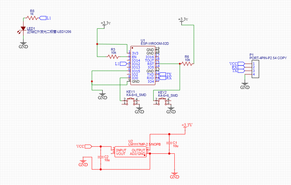
To know more about PCB design using EasyEDA, please look up my week 9 tutorial.
After finalizing the PCB designs, I generated a Bill of Materials (BOM) using EasyEDA's built-in BOM generator. This BOM listed all the components needed for the project. Next, I requested the components using the Fab Stash, our lab's inventory management app, ensuring I had all the necessary parts for assembly.
| Number | Part Name | Specification | Quantity |
|---|---|---|---|
| 1 | Capacitor | 10uF | 2 |
| 2 | Switch | K4-6×6_SMD | 2 |
| 3 | Connector | PORT-4PIN-P2.54 | 1 |
| 4 | Resistor | 10kΩ | 2 |
| 5 | Resistor | 1kΩ | 1 |
| 6 | ESP Module | ESP-WROOM-02D | 1 |
| 7 | Voltage Regulator | LM1117MP-2.5/NOPB | 1 |
| 8 | LED | LED1206-RD | 1 |
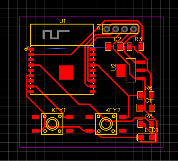
After designing the PCB layouts for my ESP-NOW communication project using EasyEDA, I exported the Gerber files and converted them into PNG images of the pads, traces, and drill holes using our lab's Gerber to PNG converter tool. These images were essential for visualizing the PCB design before manufacturing. Then, following the fabrication methods discussed during the Embedded Production Week, I used the PNG files to mill my PCB on the Modela milling machine. This fabrication process allowed me to create precise and customized PCBs for my project, ensuring proper connectivity and functionality of the ESP-NOW communication system.
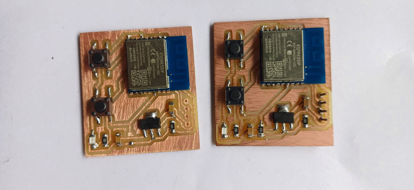
With the components in hand, I proceeded to solder the two PCBs together. Following the soldering process, I verified the connections and tested the functionality of the ESP-NOW communication system. This involved checking for proper signal transmission between the sender and receiver devices and ensuring that the OLED display showed accurate temperature and humidity readings. Through careful assembly and testing, I successfully completed the project, readying it for deployment in my IoT application.
To send messages between WROOM-02DA boards, each board needs a unique MAC address. Below is the Arduino code that retrieves the MAC address of an WROOM-02DA board:
#include <WiFi.h>
#include <esp_wifi.h>

void readMacAddress(){
  uint8_t baseMac[6];
  esp_err_t ret = esp_wifi_get_mac(WIFI_IF_STA, baseMac);
  if (ret == ESP_OK) {
    Serial.printf("%02x:%02x:%02x:%02x:%02x:%02x\n",
                  baseMac[0], baseMac[1], baseMac[2],
                  baseMac[3], baseMac[4], baseMac[5]);
  } else {
    Serial.println("Failed to read MAC address");
  }
}

void setup(){
  Serial.begin(115200);

  WiFi.mode(WIFI_STA);
  WiFi.begin();

  Serial.print("[DEFAULT] WROOM-02DA  Board MAC Address: ");
  readMacAddress();
}

void loop(){
  // Empty loop
}
The provided Arduino code retrieves the MAC address of an WROOM-02DA board using the ESP-IDF (Espressif IoT Development Framework) library functions:
#include <WiFi.h> and #include <esp_wifi.h>: Include the necessary libraries for WiFi and ESP-IDF functions.void readMacAddress(): Function to read and print the MAC address of the WROOM-02DA board.esp_err_t ret = esp_wifi_get_mac(WIFI_IF_STA, baseMac);: Retrieve the MAC address of the WROOM-02DA board in station mode (WIFI_IF_STA) and store it in the baseMac array.if (ret == ESP_OK): Check if the MAC address retrieval was successful.Serial.printf("%02x:%02x:%02x:%02x:%02x:%02x\n", baseMac[0], baseMac[1], baseMac[2], baseMac[3], baseMac[4], baseMac[5]);: Print the MAC address in hexadecimal format.Serial.println("Failed to read MAC address");: Print an error message if reading the MAC address fails.void setup(): Arduino setup function where serial communication is initialized and WiFi mode is set to station mode (WIFI_STA).void loop(): Arduino loop function, which remains empty in this example as the code executes once during setup.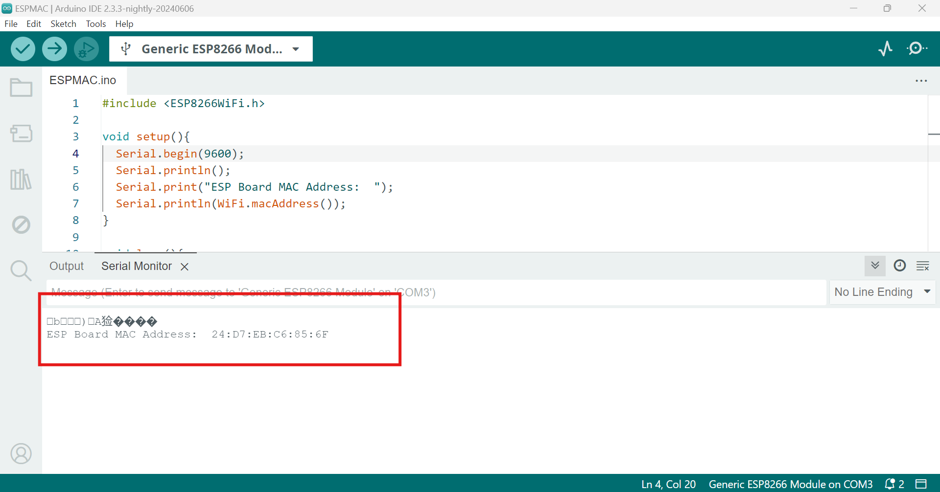
        #include <ESP8266WiFi.h>
        #include <espnow.h>

        // Replace with receiver MAC Addresses
        uint8_t slave1Address[] = {0xDC, 0x4F, 0x22, 0x62, 0xFA, 0x0A};
        uint8_t slave2Address[] = {0xDC, 0x4F, 0x22, 0x62, 0xF9, 0xFA};

        typedef struct struct_message {
          char message[32];
        } struct_message;

        struct_message myData;

        void OnDataSent(uint8_t *mac_addr, uint8_t sendStatus) {
          Serial.print("Last Packet Send Status: ");
          if (sendStatus == 0){
            Serial.println("Delivery success");
          } else {
            Serial.println("Delivery fail");
          }
        }

        void setup() {
          Serial.begin(115200); // Initialize serial communication for debugging

          WiFi.mode(WIFI_STA); // Set ESP8266 as a Wi-Fi station

          if (esp_now_init() != 0) {
            Serial.println("Error initializing ESP-NOW");
            return;
          }

          esp_now_set_self_role(ESP_NOW_ROLE_CONTROLLER); // Set device role
          esp_now_register_send_cb(OnDataSent); // Register callback for send status

          esp_now_add_peer(slave1Address, ESP_NOW_ROLE_SLAVE, 1, NULL, 0); // Add Slave 1 as a peer
          esp_now_add_peer(slave2Address, ESP_NOW_ROLE_SLAVE, 1, NULL, 0); // Add Slave 2 as a peer
        }

        void loop() {
          static int state = 0;
          static String ledStatus;

          if (Serial.available() > 0) {
            if (state == 0) {
              ledStatus = Serial.readStringUntil('\n');
              if (ledStatus == "1" || ledStatus == "0") {
                ledStatus.toCharArray(myData.message, 32);
                Serial.println("Enter node number to send to (1, 2, or A):");
                state = 1;
              } else {
                Serial.println("Invalid LED status. Please enter 1 (on) or 0 (off).");
              }
            } else if (state == 1) {
              String node = Serial.readStringUntil('\n');

              if (node == "1") {
                esp_now_send(slave1Address, (uint8_t *) &myData, sizeof(myData));
                Serial.println("Sent data to Slave 1");
              } else if (node == "2") {
                esp_now_send(slave2Address, (uint8_t *) &myData, sizeof(myData));
                Serial.println("Sent data to Slave 2");
              } else if (node == "A") {
                esp_now_send(slave1Address, (uint8_t *) &myData, sizeof(myData));
                esp_now_send(slave2Address, (uint8_t *) &myData, sizeof(myData));
                Serial.println("Sent data to both Slaves");
              } else {
                Serial.println("Invalid node number. Please enter 1, 2, or A.");
              }

              state = 0;
            }
          }
        }
Includes necessary libraries for ESP8266 Wi-Fi functionality and ESP-NOW communication.
Defines MAC addresses of the two ESP8266 modules (slave1Address and slave2Address) that will receive data.
Defines a struct_message structure with a message array to store data that will be sent.
Callback function triggered after data is sent, indicating the delivery status via Serial monitor.
Initializes the ESP8266 module:
OnDataSent callback function.slave1 and slave2) as peers.Continuously checks for input from the Serial monitor:
              #include <ESP8266WiFi.h>
              #include <espnow.h>

              // Structure example to receive data
              typedef struct struct_message {
                char message[32];
              } struct_message;

              // Create a struct_message called myData
              struct_message myData;

              const int ledPin = 12; // Change to your actual LED pin

              // Callback function that will be executed when data is received
              void OnDataRecv(uint8_t *mac, uint8_t *incomingData, uint8_t len) {
                // Copy received data into myData structure
                memcpy(&myData, incomingData, sizeof(myData));

                // Print received data details
                Serial.print("Bytes received: ");
                Serial.println(len);
                Serial.print("Message: ");
                Serial.println(myData.message);

                // Control LED based on the received message
                if (String(myData.message) == "1") {
                  digitalWrite(ledPin, HIGH); // Turn on LED
                } else if (String(myData.message) == "0") {
                  digitalWrite(ledPin, LOW); // Turn off LED
                }
              }

              void setup() {
                // Initialize Serial Monitor
                Serial.begin(115200);

                // Set device as a Wi-Fi Station
                WiFi.mode(WIFI_STA);

                // Initialize ESP-NOW
                if (esp_now_init() != 0) {
                  Serial.println("Error initializing ESP-NOW");
                  return;
                }

                // Set device role as a slave and register callback function for received data
                esp_now_set_self_role(ESP_NOW_ROLE_SLAVE);
                esp_now_register_recv_cb(OnDataRecv);

                // Initialize LED pin as output
                pinMode(ledPin, OUTPUT);
              }

              void loop() {
                // Empty loop as all functionality is handled in the callback function
              }
Includes necessary libraries for ESP8266 Wi-Fi functionality and ESP-NOW communication.
#include <ESP8266WiFi.h>
#include <espnow.h>
Defines a structure struct_message to encapsulate received data with a message field of maximum 32 characters.
typedef struct struct_message {
  char message[32];
} struct_message;
Defines myData to store incoming data and ledPin to specify the digital pin connected to an LED.
struct_message myData;
const int ledPin = 12; // Change to your actual LED pin
Executed when data is received via ESP-NOW. Copies received data into myData structure and controls the LED based on the received message.
void OnDataRecv(uint8_t *mac, uint8_t *incomingData, uint8_t len) {
  memcpy(&myData, incomingData, sizeof(myData));
  Serial.print("Bytes received: ");
  Serial.println(len);
  Serial.print("Message: ");
  Serial.println(myData.message);

  if (String(myData.message) == "1") {
    digitalWrite(ledPin, HIGH);
  } else if (String(myData.message) == "0") {
    digitalWrite(ledPin, LOW);
  }
}
Initializes the ESP8266 module, sets up ESP-NOW communication, and configures the LED pin.
void setup() {
  // Initialize Serial Monitor
  Serial.begin(115200);

  // Set device as a Wi-Fi Station
  WiFi.mode(WIFI_STA);

  // Init ESP-NOW
  if (esp_now_init() != 0) {
    Serial.println("Error initializing ESP-NOW");
    return;
  }

  // Register for recv CB to get recv packet info
  esp_now_set_self_role(ESP_NOW_ROLE_SLAVE);
  esp_now_register_recv_cb(OnDataRecv);

  // Initialize LED pin
  pinMode(ledPin, OUTPUT);
}
Empty loop function as all functionality is handled in the callback function.
void loop() {
  // Empty loop as all functionality is handled in the callback function
}
OnDataSent) to monitor the transmission status of data packets.struct_message structure.esp_now_send function to transmit this data to the registered secondary nodes (slaves).slave1Address and slave2Address).OnDataSent callback function handles the acknowledgment and status of each data packet sent, printing "Delivery success" or "Delivery fail" based on the transmission outcome.OnDataRecv) to handle incoming data.OnDataRecv callback function is triggered upon receiving data. It extracts the received message from the data packet and processes it.myData.message) is interpreted to control an LED. If the message is "1", the LED is turned on; if "0", the LED is turned off.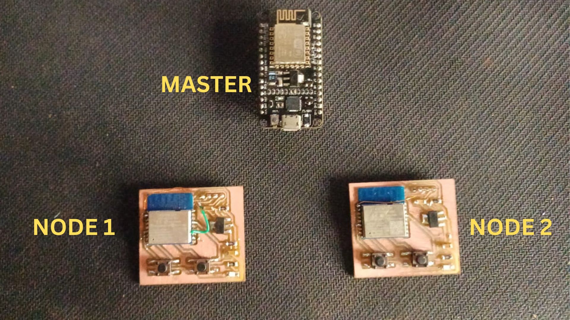
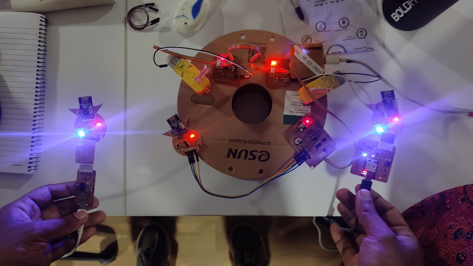
the above image shows how the nods are connected together i used one esp8266 as master node and 2 secondary nods wroom 2D module
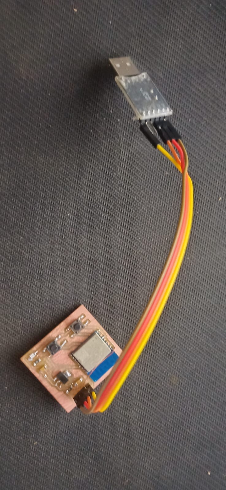
A USB to TTL (Transistor-Transistor Logic) converter is a device that allows a computer to communicate with serial devices using the USB port. It converts USB signals into TTL signals, which are commonly used in microcontroller and embedded system applications. This converter is essential for programming and debugging microcontrollers and other devices that use serial communication.
To program the ESP WROOM 2D module using a USB to TTL converter, connect the pins as follows:
| USB to TTL Converter Pin | ESP WROOM 2D Pin | Description |
|---|---|---|
| VCC | VCC | Provides power to the ESP WROOM 2D |
| GND | GND | Common ground connection |
| TXD | RXD | Transmit data from USB to TTL to RXD |
| RXD | TXD | Receive data from TXD to USB to TTL |
| DTR (optional) | EN | Used for auto-reset functionality |
| RTS (optional) | GPIO0 | Used to put the ESP in boot mode |
The USB TO TTL CONVERTER simplifies programming and debugging of microcontroller-based systems by converting USB signals to a format compatible with UART interfaces, easing hardware communication complexities.
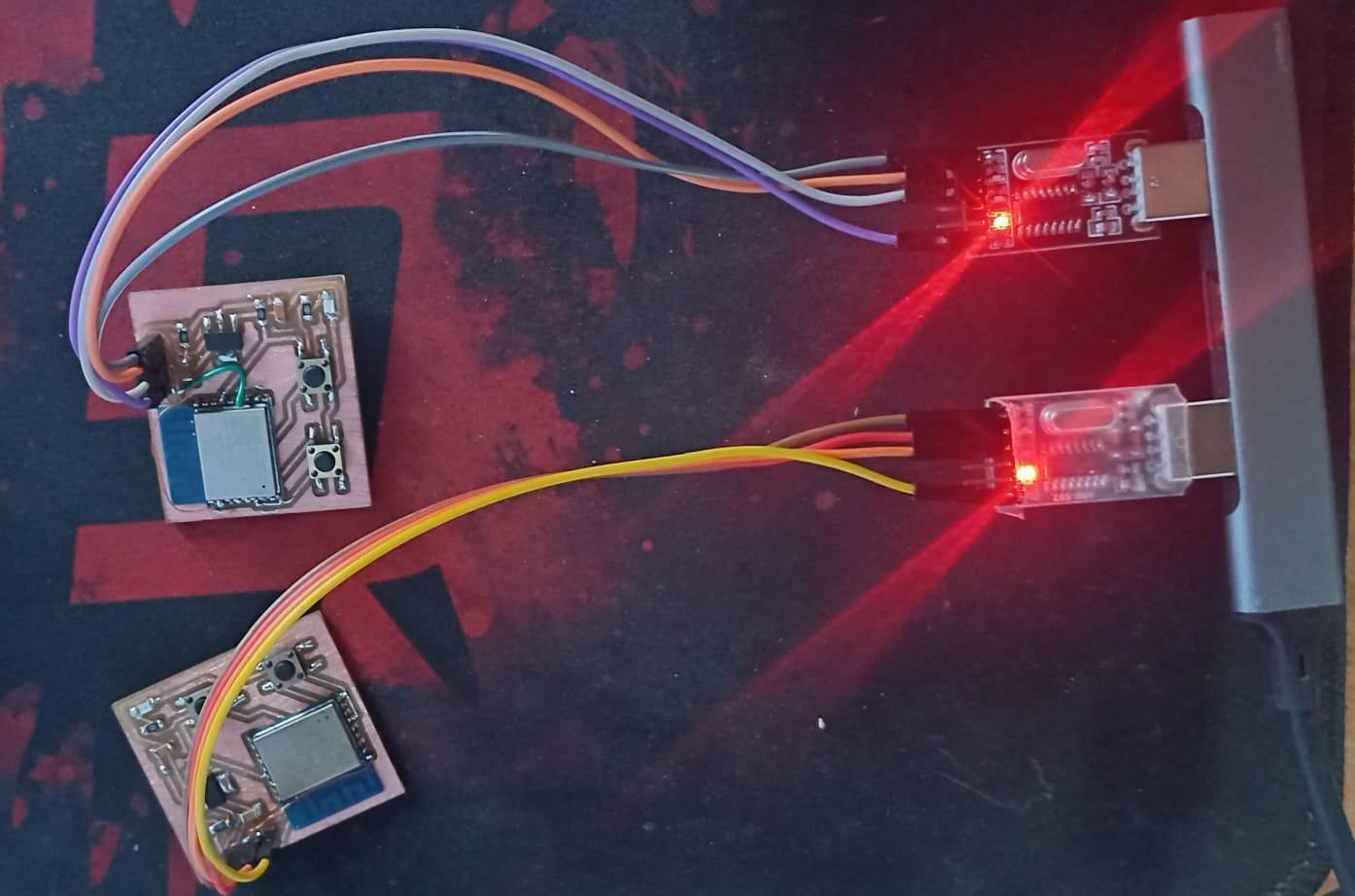
afetr uploaing the code i powerd up the esp 8266 master and opened serial moniter and started to send the data
 see the group assingment here