Week 10 Assignment
MACHINE WEEK
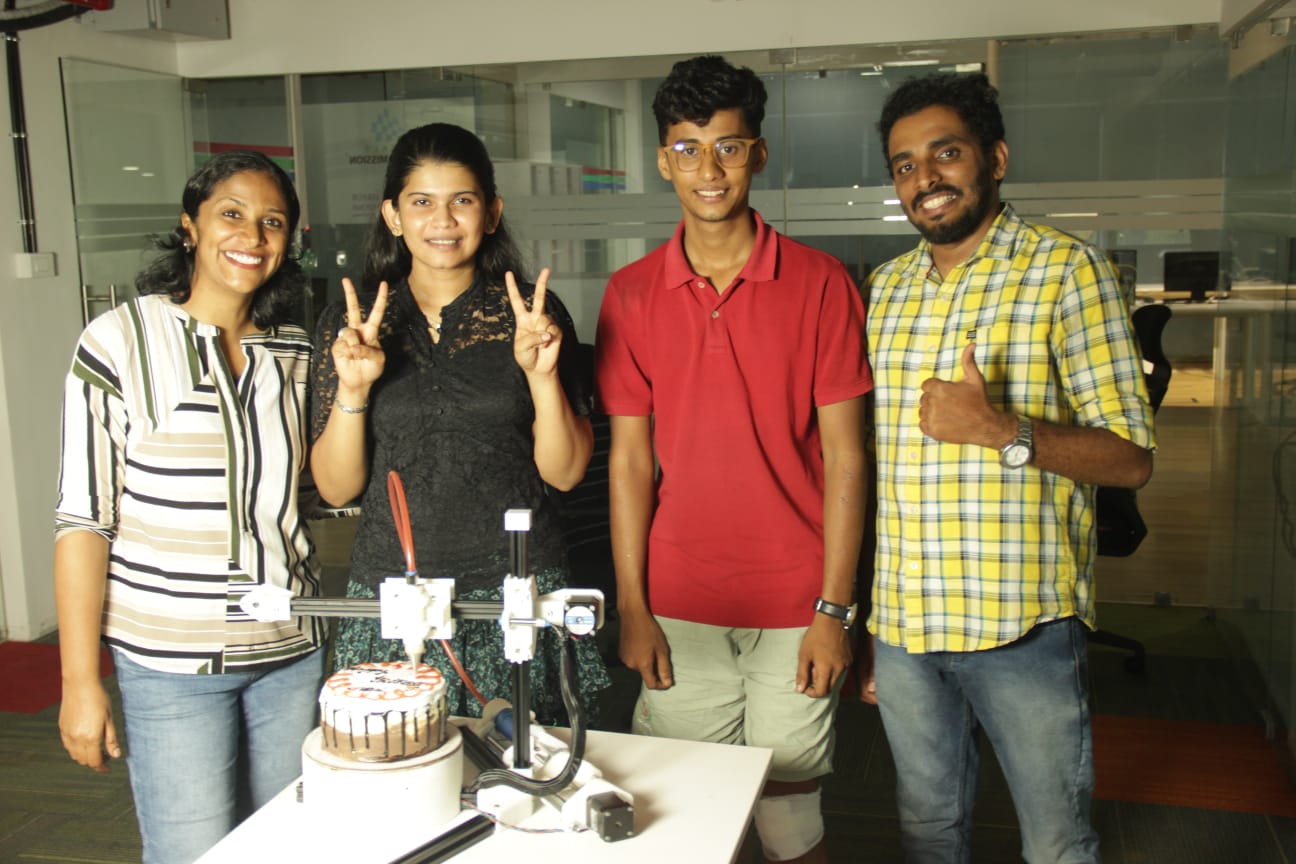
This week it is all about building a machine and we chose to build a cake decorating machine. I took up the challenge in coming up with the basic ideas and the entire product development cycle.
Group Assignmentlink to our group assignment
I came up with a basic idea and referenced it from a 3D printer that I saw.
Cakerator2000 Design Details
Design Overview
As the team lead, I spearheaded the development of the Cakerator2000, a state-of-the-art cake decorating machine that seamlessly blends engineering precision with a deep appreciation for baking. Our project emerged from a collective ambition to innovate and address the challenges faced by home bakers, particularly in achieving intricate and precise cake decorations.
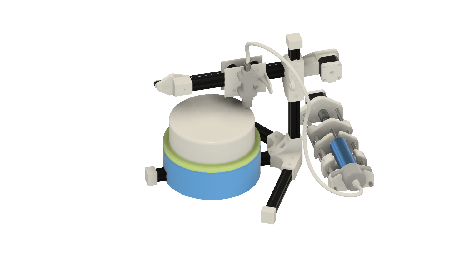
Structural Framework and 3D Printing
The structural framework of the Cakerator2000 incorporates a strategic use of 3D printed parts, chosen for their versatility and customization capabilities. We utilized 3D printing extensively, employing a 25% infill density and configuring structural parts with 6 parameters for robustness, while non-structural components were designed with 4 parameters to balance strength and weight.
Key Components
Turntable and Bearings
The entire turntable, a pivotal element for rotational movement, was 3D printed. This approach allowed us to achieve complex geometries and precise dimensions, ensuring stable and precise rotation. It operates smoothly on 608 bearings at the ends and a robust 6702 bearing in the center, essential for achieving uniform icing distribution on cakes of various sizes.
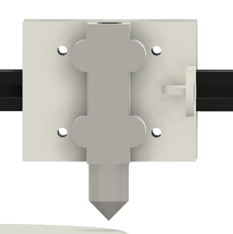
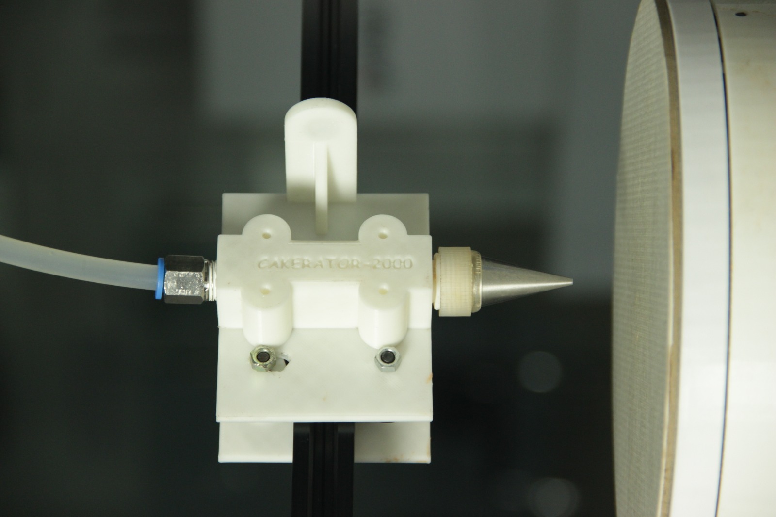
Plunger Mechanism and Nozzle Holder
The plunger mechanism, crucial for precise icing application, incorporates 3D printed components designed to support and guide the icing gun effectively. We integrated a custom nozzle holder, also 3D printed, equipped with a magnetic snap-on mechanism for quick and effortless nozzle changes. This innovative design enhances usability and maintenance efficiency during cake decorating sessions.
Drive Mechanism and Control Systems
Driving the rotational movement is a NEMA 17 stepper motor integrated with a precise spur gear mechanism. This combination provides reliable torque and precise angular control, facilitating consistent and accurate cake decoration.
For height adjustment (Z-axis), we implemented a manual control system with dual lock nuts, allowing fine adjustments tailored to different cake heights. Linear movement across the cake surface is facilitated by a carriage system using POM wheels and a timing belt with slotted belt tensioning, ensuring smooth operation and positional accuracy.
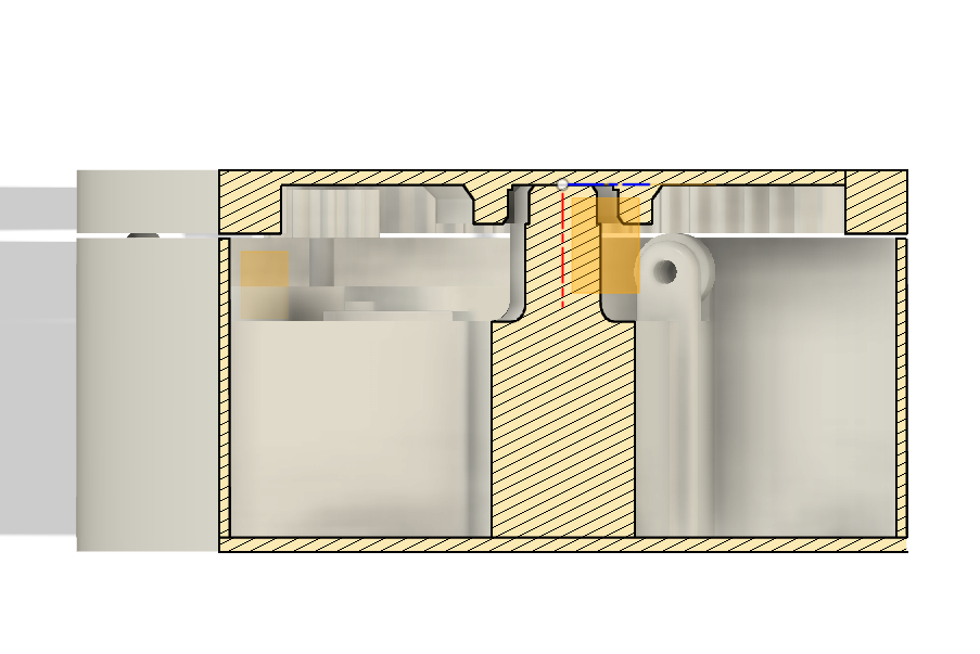
Icing Delivery System
Central to the Cakerator2000 is its sophisticated icing delivery system. I designed a specialized extruder mechanism that efficiently transfers icing from the reservoir through an 8mm nylon tube to the nozzle. This setup guarantees controlled and uniform icing application, enhancing both efficiency and the aesthetic quality of cake decorations.
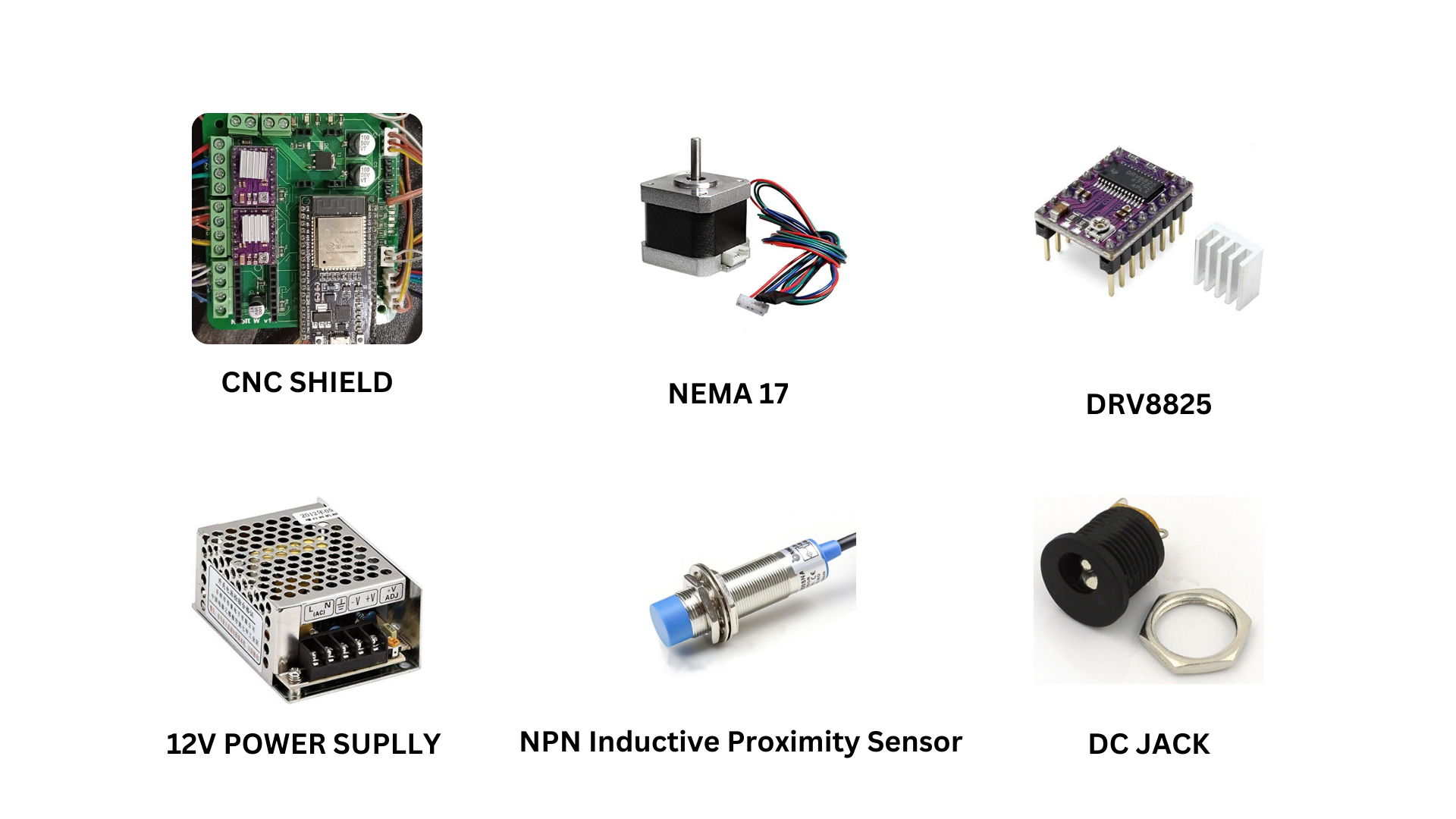
ELECTRONICS
After we assembled the structure, we added the necessary electronic parts and added the controller board, which is an ESP32-based CNC shield. We started the basic tests by sending out G-codes to draw test squares. The issue was that the icing was too thick because of the cold, so we resorted to using ketchup to simulate the icing.
| Component | Quantity | Description |
|---|---|---|
| NEMA 17 Stepper Motor | 3 | High-torque stepper motor for precise movement control |
| DRV8825 Motor Driver | 3 | Stepper motor driver for controlling NEMA 17 motors |
| ESP32-based CNC Shield | 1 | Control board for managing stepper motors and other peripherals |
| DC Jack | 1 | Power connector for the power supply |
| 12V 5A Power Supply | 1 | Power supply unit to provide sufficient power to the system |
| Inductive Sensor | 1 | Used as a limit switch for position sensing |
ASSEMBLY
We came together and assembled the entire unit. There were fitting issues which we solved by grinding and using hand tools.
TEST
We used the web interface of the ESP32 to send test G-codes to the machine and make it draw a square to test that the system is responding well. Eventually, we were able to crack it.
        G21         ; Set units to millimeters
        G90         ; Use absolute positioning

        G0 X0 Y0 Z0 ; Move to the origin
        G10 L20 P1 X0 Y0 Z0 ; Set the work coordinate system origin to the current position

        ; Now, the following movements will be based on this new origin
        G1 X50 Y0 F500 ; Draw a line to (50,0)
        G1 X50 Y50 F500 ; Draw a line to (50,50)
        G1 X0 Y50 F500 ; Draw a line to (0,50)
        G1 X0 Y0 F500 ; Draw a line back to the origin
FINAL OUTPUT
Then we proceeded to draw a simple cake decoration using Fusion and imported it to G-code. We uploaded it, also adding a line to set the extrusion length. We used a Python script to add it; it will calculate the feed rate using the travel distance from the travel distance of the X and Y axes.