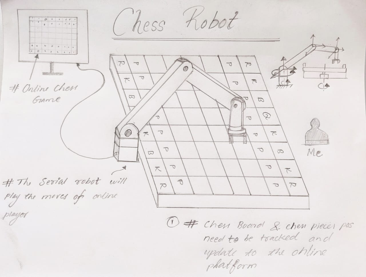
Online Chess to Offline Chess Converting Serial Robot
This project is designed to bridge the gap between digital and physical chess. The robot is programmed to replicate on a physical chessboard the moves made in an online game. This allows players to enjoy the tactile experience of traditional chess while benefiting from the convenience and wide player base of online platforms. Whether used for practice, exhibition, or just for fun, this project brings a new dimension to the timeless game of chess.
In addition, the chessboard also captures the moves made by the offline player and feeds them back into the online game. This two-way interaction ensures a seamless integration between the online and offline platforms, providing a truly immersive experience.
Robotic Assistant for Disabled Chess Players
This project aimed to make the game of chess more accessible to people with physical disabilities. This robotic assistant is equipped with voice control functions, allowing players to dictate their moves without having to physically move the pieces.
The assistant is designed to understand a wide range of voice commands, can recognize standard chess move notation, and is capable of accurately moving the pieces to the correct positions on the board. This allows players with disabilities to compete on an equal footing, removing physical limitations from the game.
Final Project Designs 1
➡️
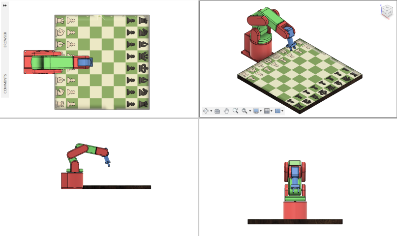
Design of Serial Robot in Fusion 360
I have decided to design my project in Fusion 360.
Open Fusion 360 and start a new design.
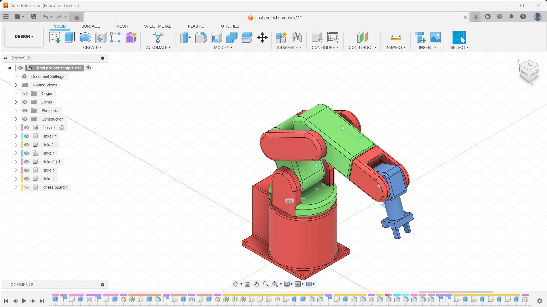
Each part and link are made using separate components from the “assemble section" 👉 "component". It helps us organize the drawings and designs .
Design the base or platform of the robotic manipulator. This may involve creating a solid body or assembly.
Model each joint and link of the manipulator based on the defined specifications. Use sketches, extrusions, and rotations to form the basic structure.
The base of the robotic arm is grounded. Revolute joints and rigid joints are added to the links of my robotic arm.
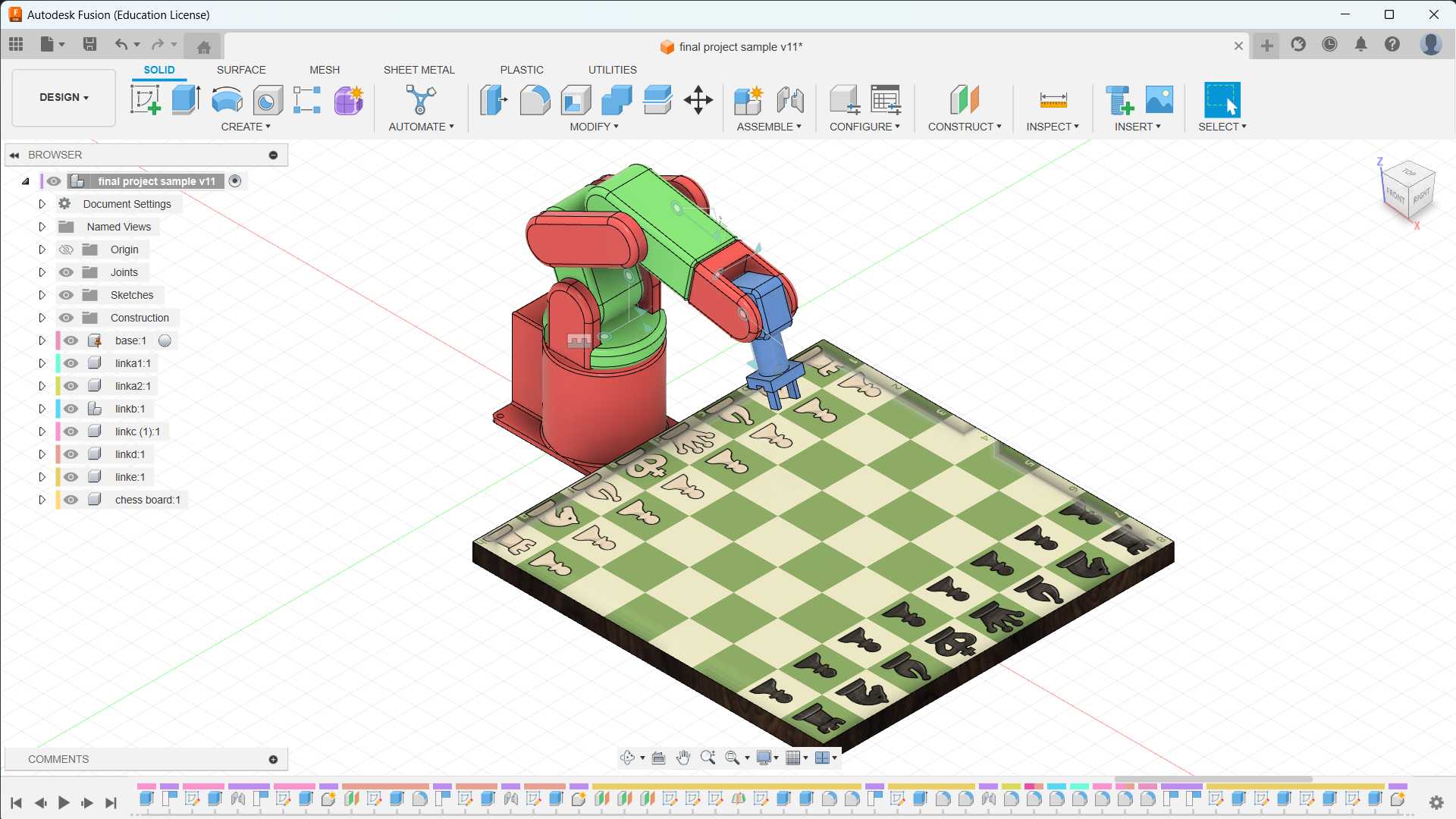
The image of the chess board is added from “insert menu” and “decal”. To change the material, select the “modify” menu and select “physical material".
To change the appearance, select the “modify” menu and select “Appearance” or press "A".
Changed the view from “single view” to “multiple view”
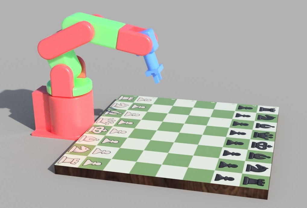
The workspace is changed from “Design” to "Render”, and select "In-Canvas Render” to render the CAD model.
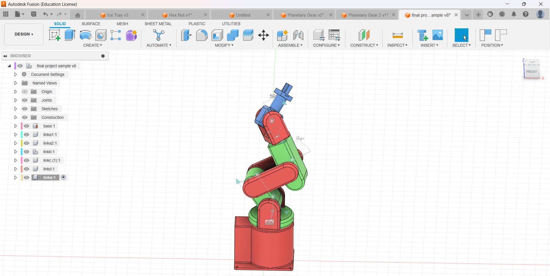
Animation in Fusion 360
Testing the NEMA 17 Stepper Motor
💡
During week 9, I decided to study and test the stepper motor for my X-Y CNC.
⬇️
Follow the link below to learn more about the testing of the Nema 17 stepper motor.
In week 9, I decided to develop a new board for exploring Nema 17 stepper motor. By designing a new board, I will get the best of both worlds by gaining expertise in PCB design using KiCAD.
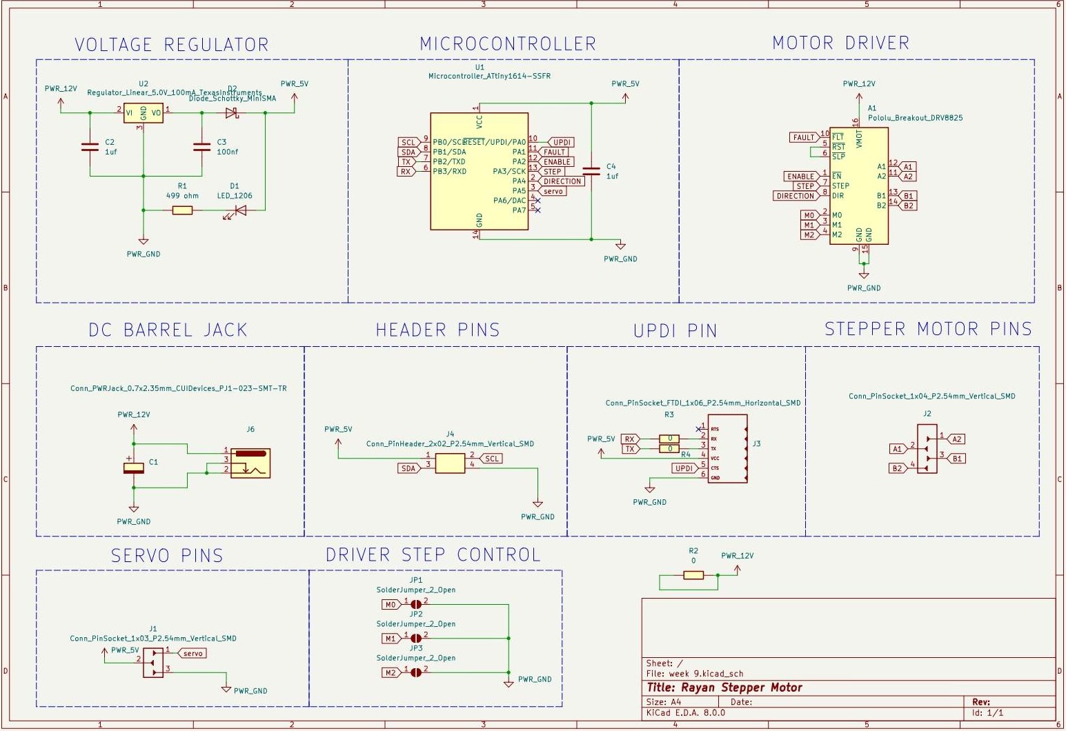
Schematic in KiCAD
⬇️
Check out the link below to learn more about PCB design using KiCAD.
The schematic diagram of the new board is shown below.
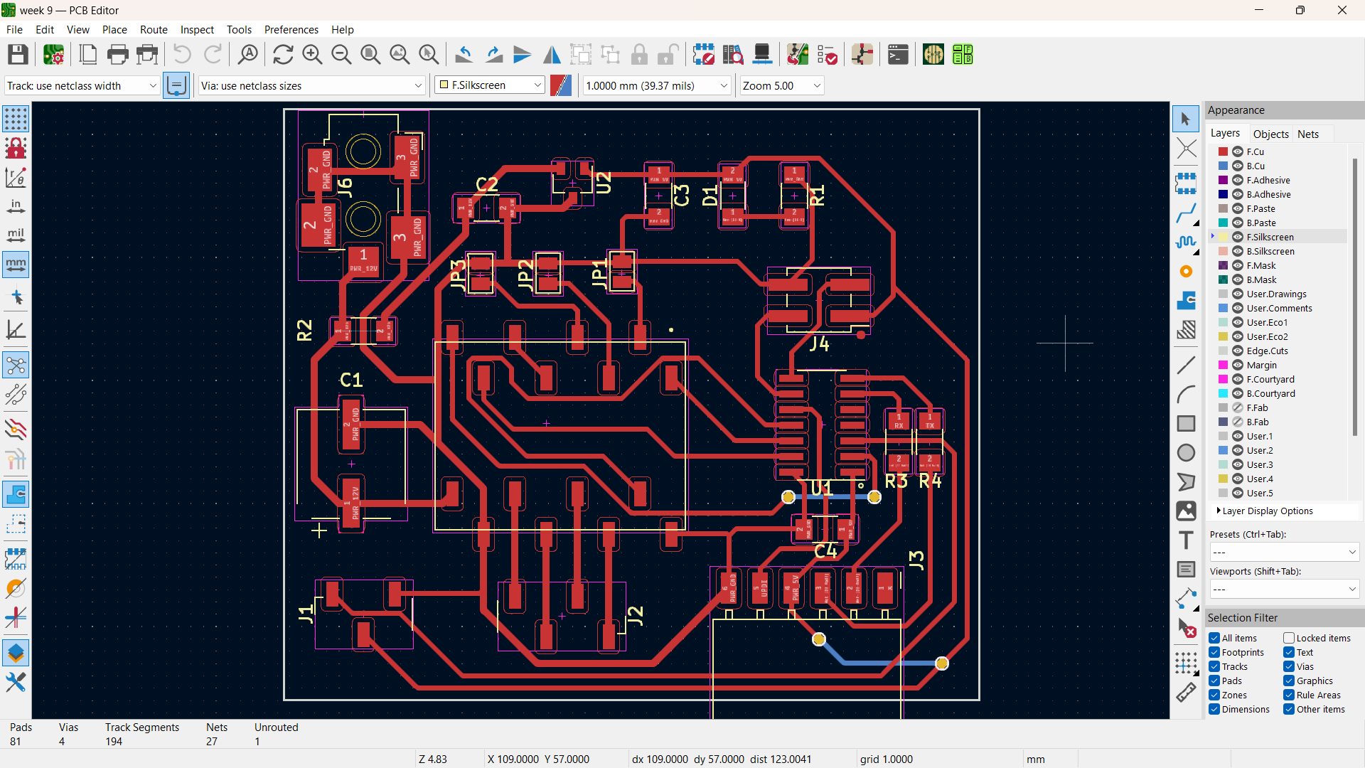
PCB Layout in KiCAD
🚨
Since the stepper motors are operated at 12 volts, the track width of the power increased to 0.6 mm, and the track width of the rest was set to 0.4 mm.
NEMA 17 with New Board
🚨
Before connecting the stepper motor, current limit need to be set on the motor driver.
🚨
This step is not very complicated but absolutely necessary to protect your stepper motor and the driver.
🚨
If you do not set an appropriate current limit, your motor can draw more current than it or your driver can handle, this is likely to damage one or both of them.
🚨
To set the current limit you need to measure a reference voltage and adjust the on-board potentiometer accordingly.
🚨
To measure the reference voltage, the driver needs to be powered. The DRV8825 only needs power via VMOT (8.2-45 V) and you need to apply 5 V to RST and SLP otherwise, the driver won’t turn on. It’s best to disconnect the stepper motor while you do this. Also, make sure the fault pin is set to high.
Current limit formula
💠
Current Limit = Vref × 2
🚨
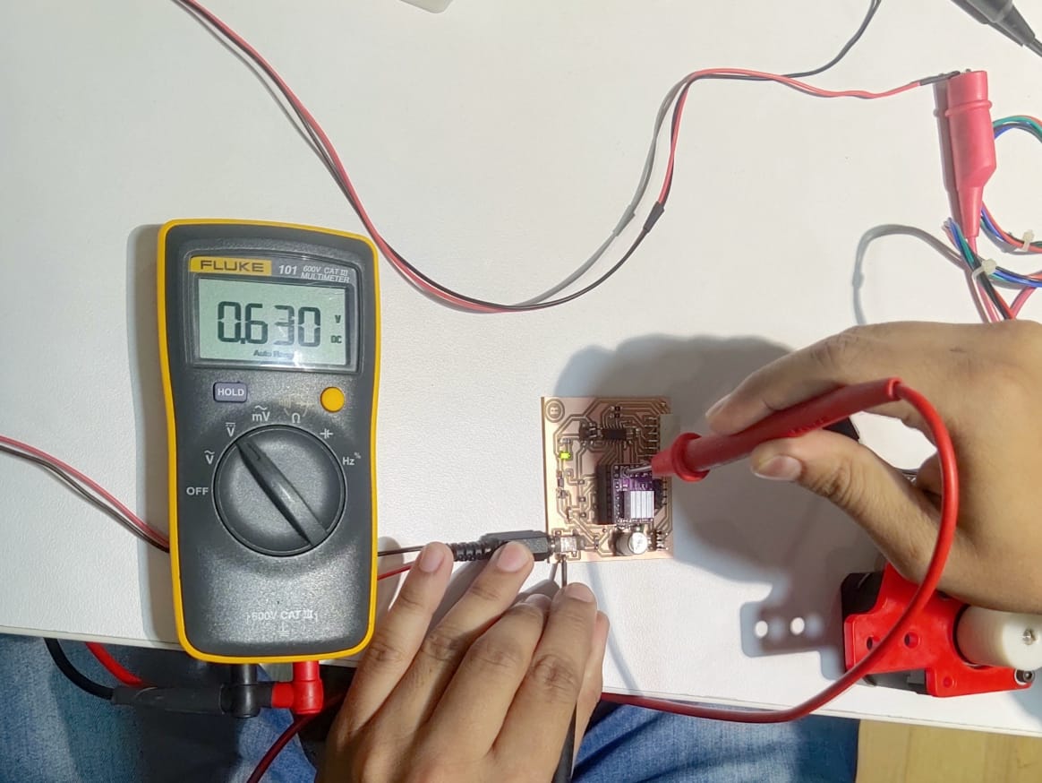
To select the right current limit, take a look at the datasheet of your stepper motor. In my case I = 1.2 A, so Vref = 0.6 V
🚨
Now you will need to measure the reference voltage (Vref) between the potentiometer and ground and adjust it to the value you calculated (for me, it is 0.6V).
🚨
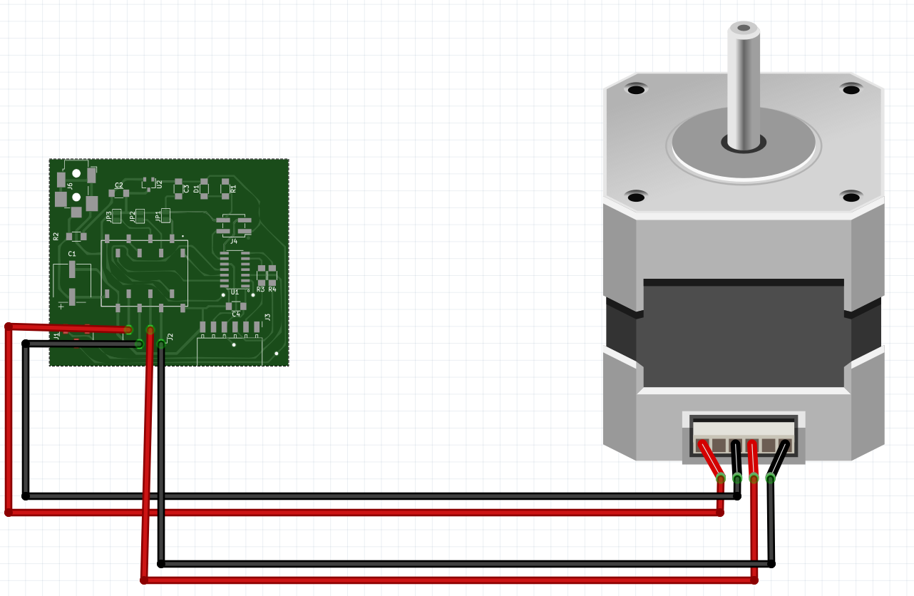
The picture below depicts the stepper motor and board connection.
😃
Final Result
Stepper motor code
const int dirPin = 0;
	const int stepPin = 10;
	const int faultPin = 8;
	const int enablePin = 9;
	const int stepsPerRevolution = 200;

	void setup()
	{
	  // Declare pins as Outputs
	  pinMode(stepPin, OUTPUT);
	  pinMode(dirPin, OUTPUT);
	  pinMode(faultPin, INPUT);
	  digitalWrite(faultPin, HIGH);
	}
	void loop()
	{
	  // Set motor direction clockwise
	  digitalWrite(dirPin, HIGH);

	  // Spin motor slowly
	  for(int x = 0; x < stepsPerRevolution; x++)
	  {
		digitalWrite(stepPin, HIGH);
		delayMicroseconds(2000);
		digitalWrite(stepPin, LOW);
		delayMicroseconds(2000);
	  }
	  delay(1000); // Wait a second

	  // Set motor direction counterclockwise
	  digitalWrite(dirPin, LOW);

	  // Spin motor quickly
	  for(int x = 0; x < stepsPerRevolution; x++)
	  {
		digitalWrite(stepPin, HIGH);
		delayMicroseconds(1000);
		digitalWrite(stepPin, LOW);
		delayMicroseconds(1000);
	  }
	  delay(1000); // Wait a second
	}
Molding and Casting Chess Piece
Chess Piece Design in Fusion 360
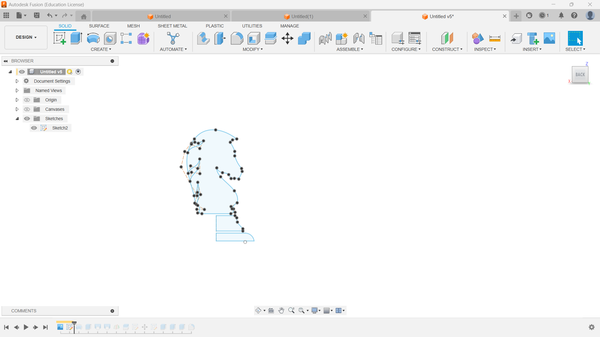
🚨
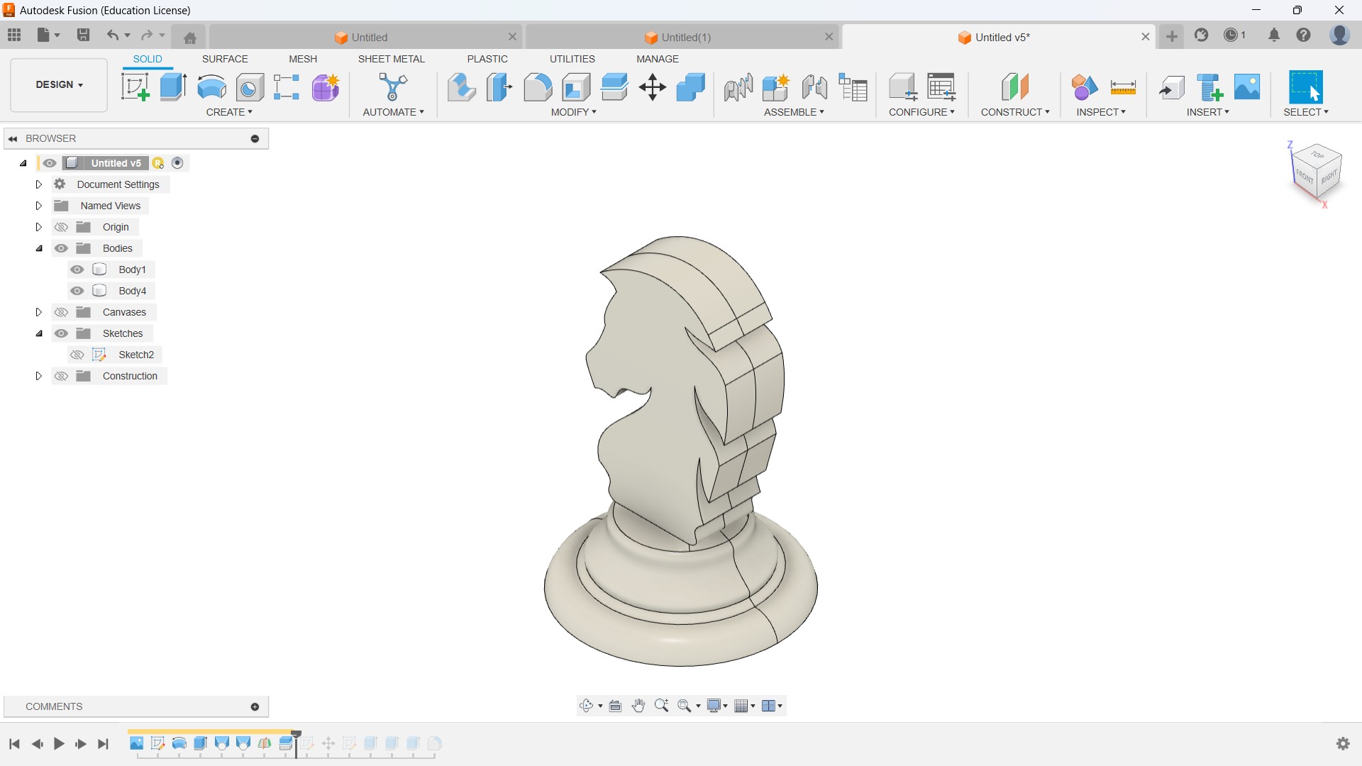
In week 12, I chose to cast a chess piece that would be useful for my final project as well, and I chose the knight because it is the most challenging part among other chess pieces. I started to design the sketch in Fusion 360.
⚠️
Always keep in mind the minimum diameter of the end mill available in our fab lab while designing the model.
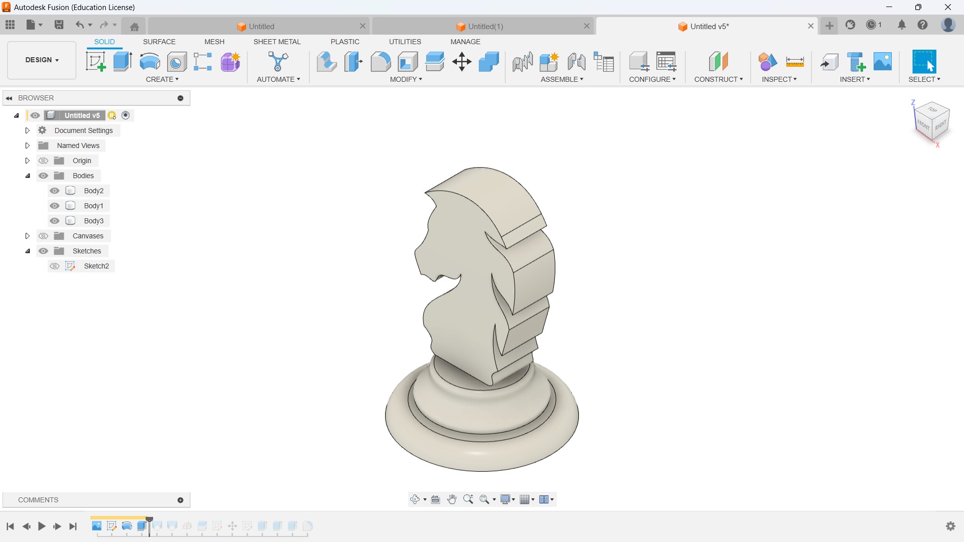
Later, I converted the sketch into 3D by extruding and revolving the sketch.
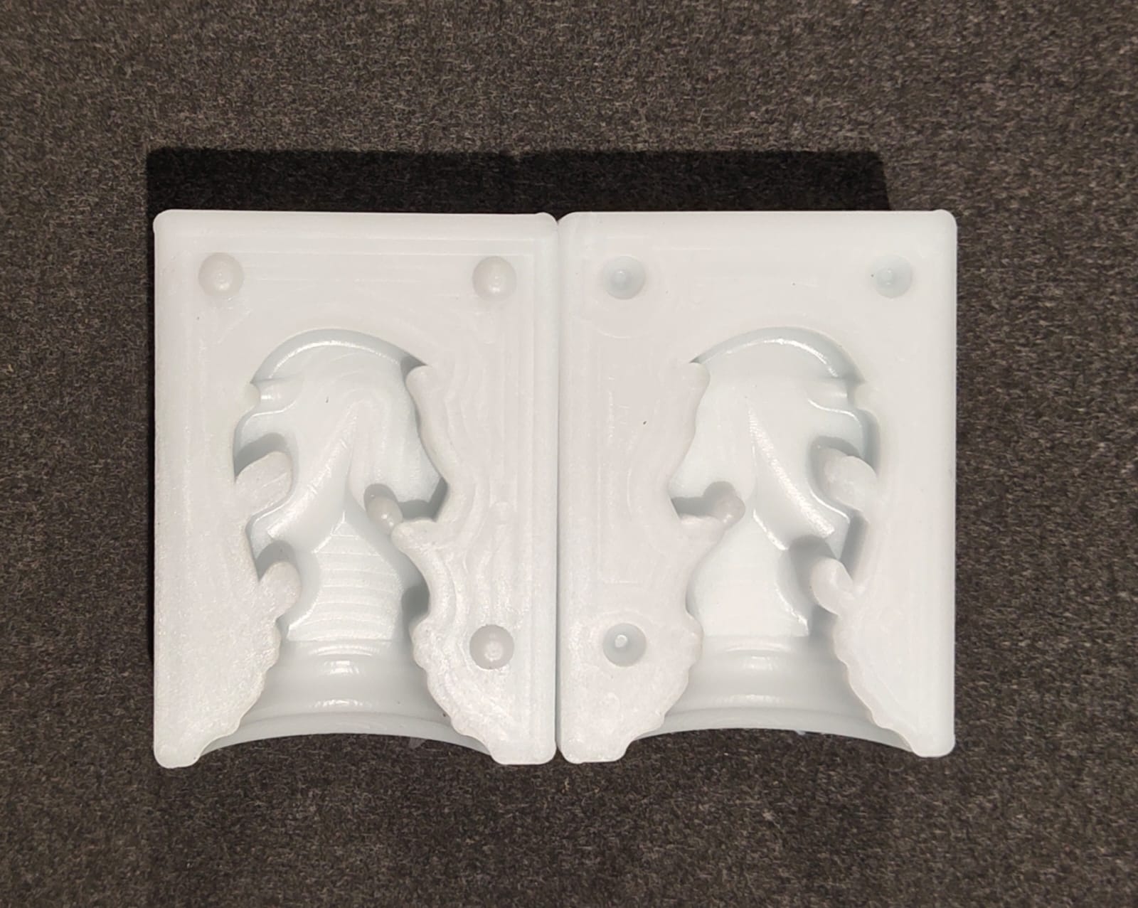
🚨
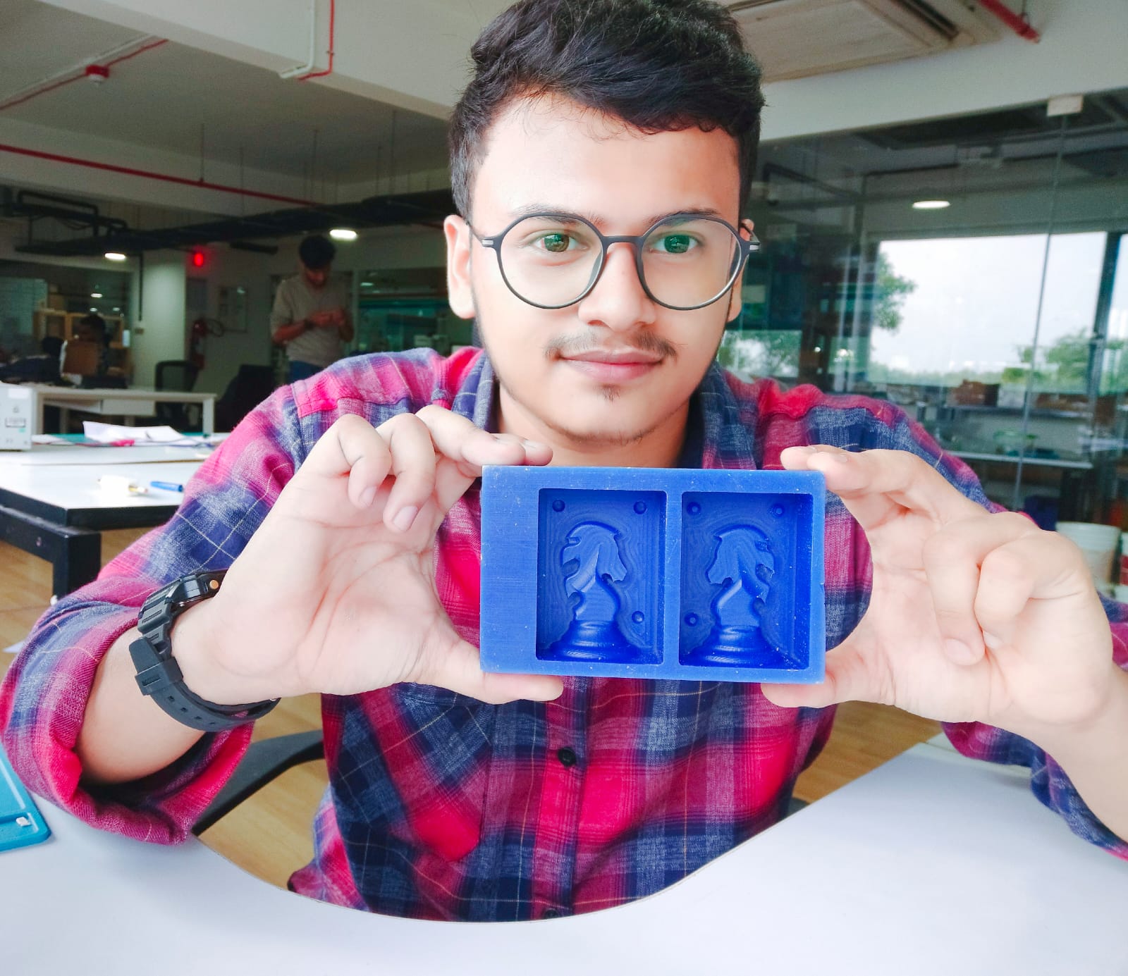
The first step in casting my piece is to create a positive part to create a negative mold. Compared to other chess pieces, I need to create a negative part for the knight because the other part is the mirror of the first part.
🚨
I created a mid-plane and split the body into two pieces.
Silicone Mold Casting
Knight Resin Casting
🚨
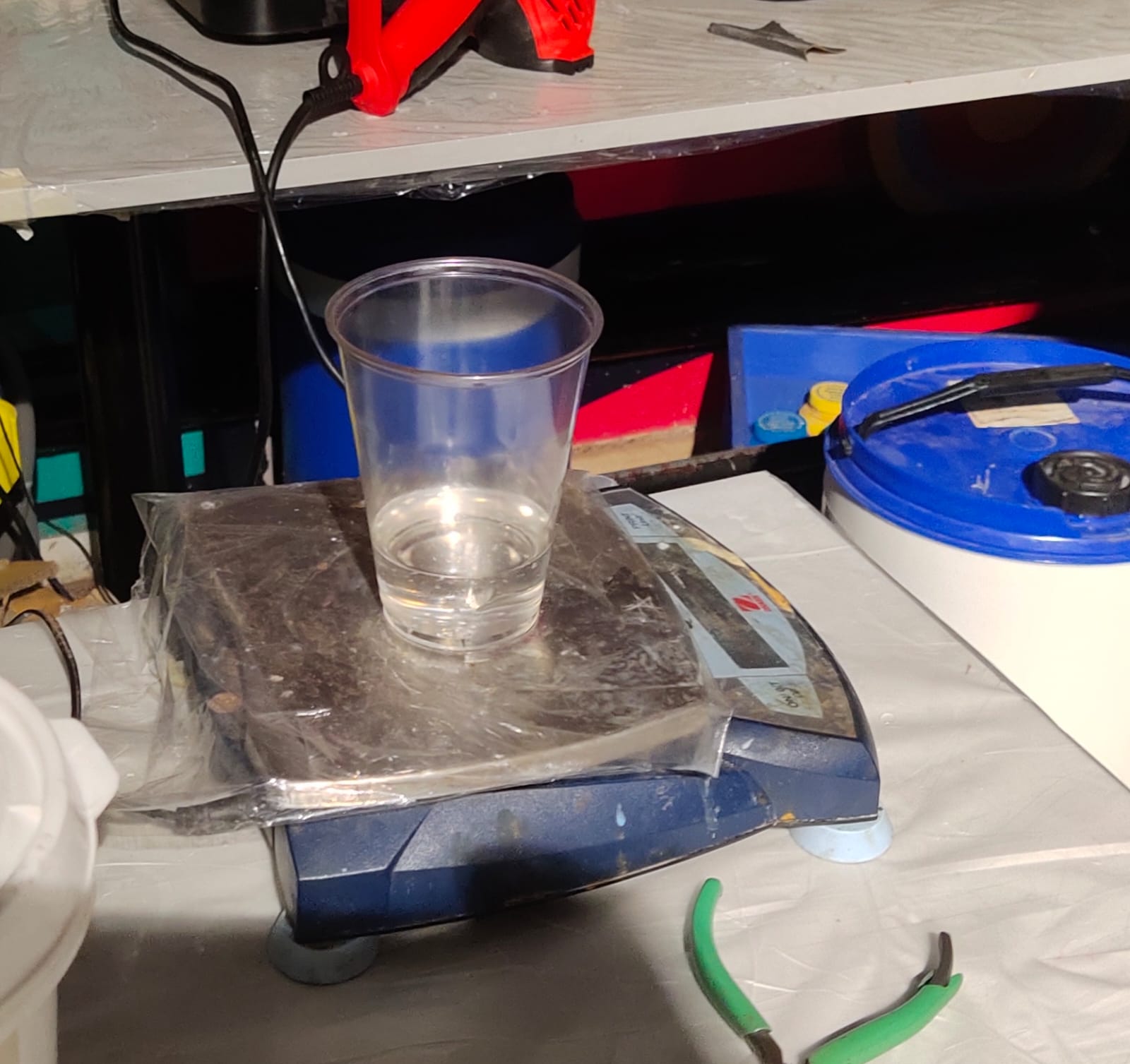
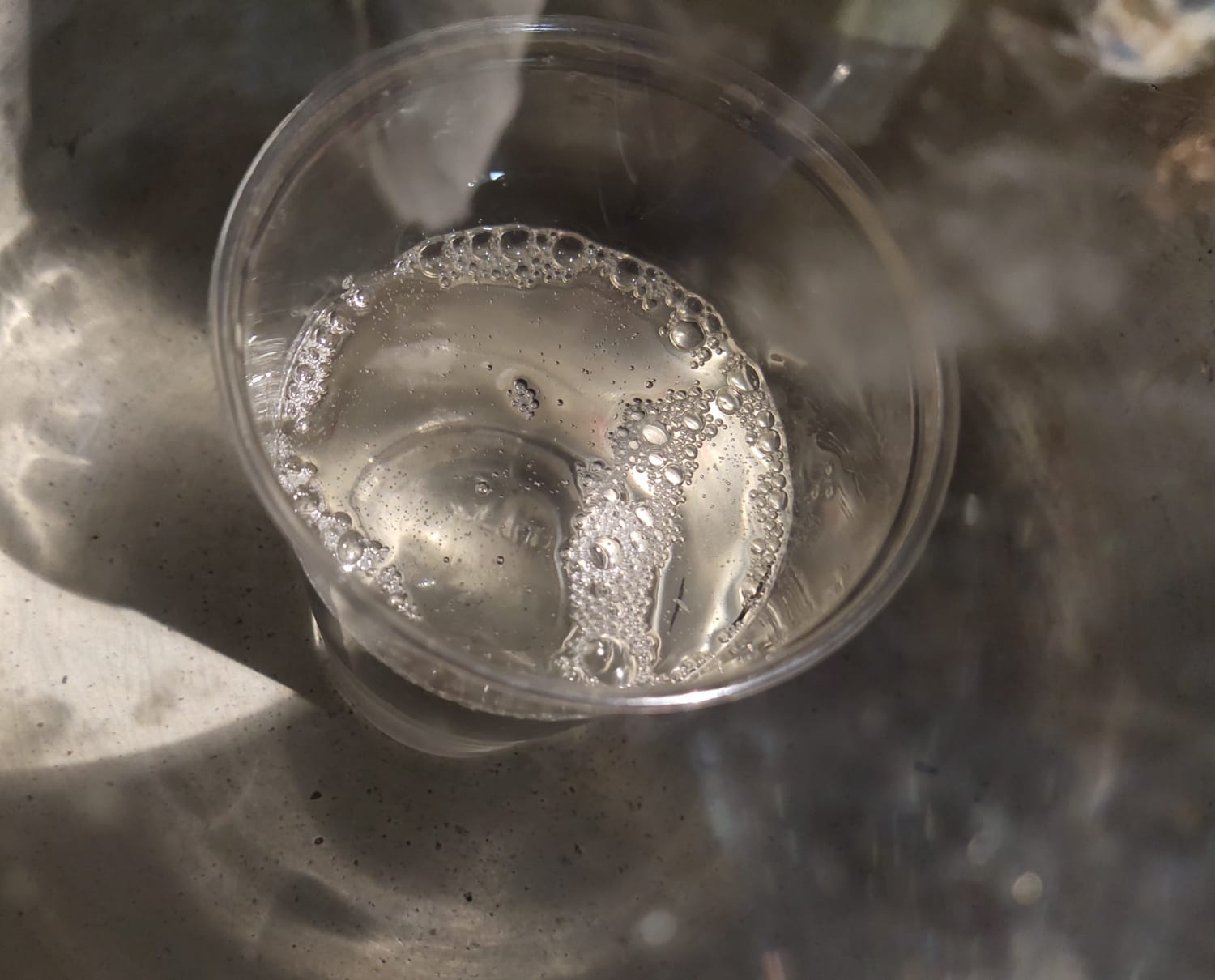
After using water to clean the mold, I added water to measure its volume and see whether any leaks were present.
🚨
To get the volume, I poured the water into a disposable transparent glass and marked the level. I considered adding a little extra water while measuring the volume.
🚨
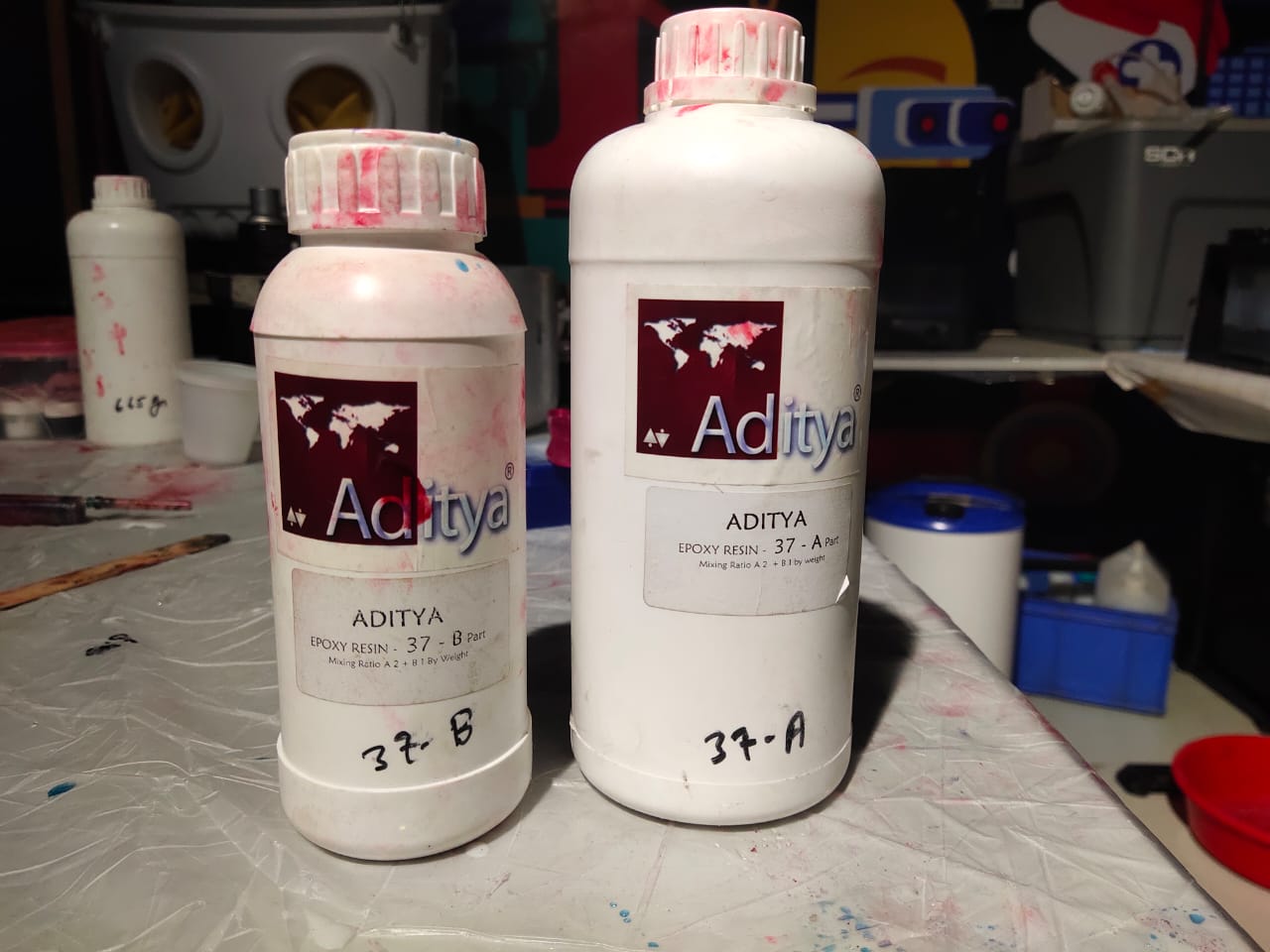
Aditya epoxy resin is the resin we use in our lab.
🚨
Epoxy resin comes in two parts: part A and part B. A2+B is the stated mixing ratio.
🧮
After mixing both parts, I need to get the volume which I marked on the glass. The amount of part A and part B resin is unknown to me. I considered amount of part B resin as X, so part A will be 2X.
🧮
Total weight = 2X + X= 3X
🧮
To get an approximate value I decided to take the total weight of the water instead of resin.
🧮
The volume of the water marked on the glass consists of the volume of the water of my peers.
🧮
So the total weight I got was 195 g.
🧮
Therefor X = 65. I added 130 g of part A and 65 g of part B and mixed properly.
🚨
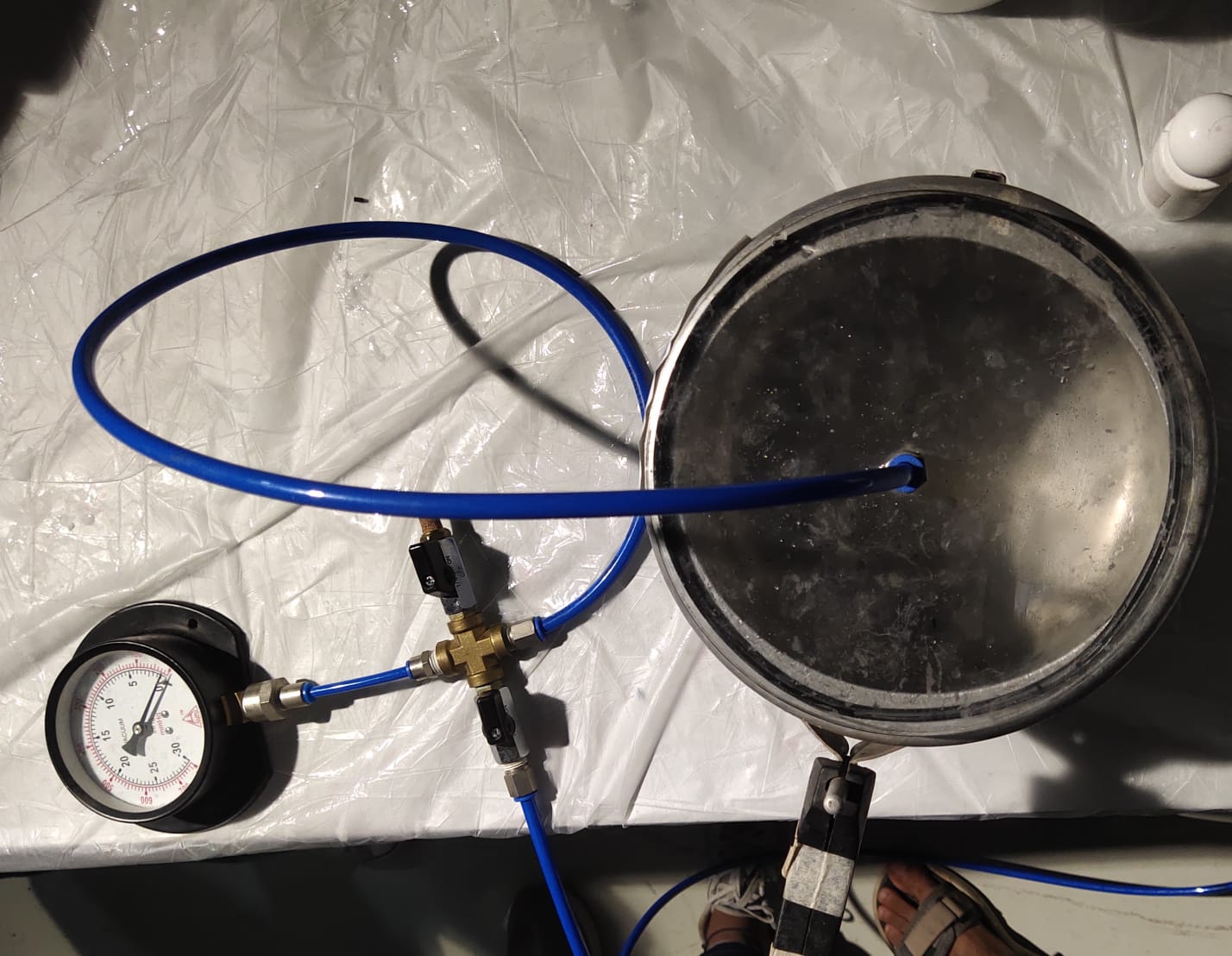
To remove the air bubbles from the resin my instructor recommended us to try out using the vacuum chamber.
🚨
The image below illustrates the mixed resin placed inside the vacuum chamber where the air bubbles are removed from the resin.
🚨
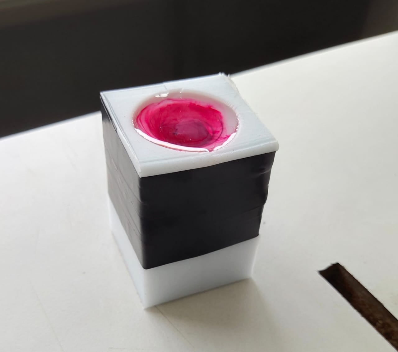
To eliminate the leakage, I used an insulation tap to combine the two molds properly.
🚨
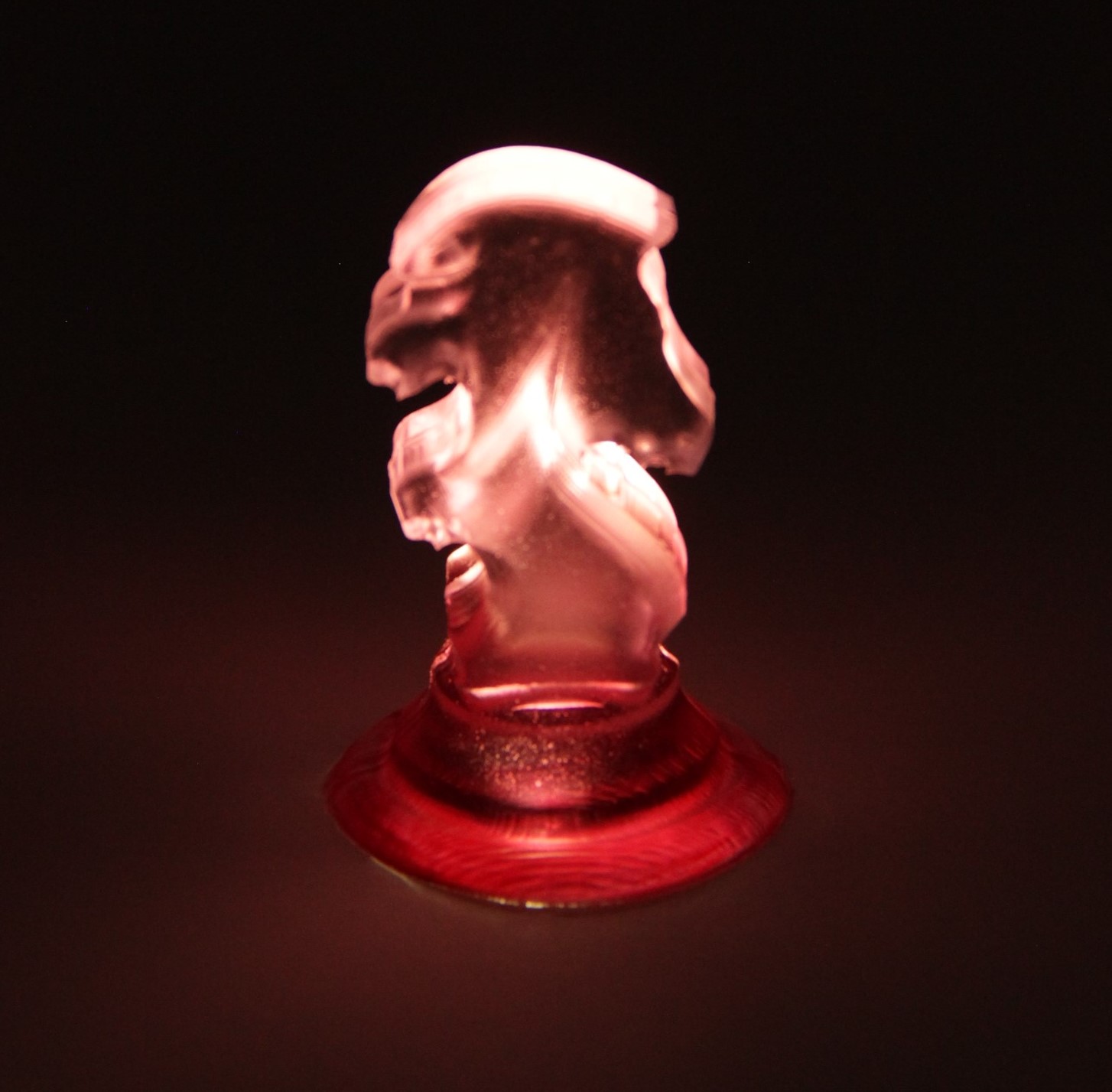
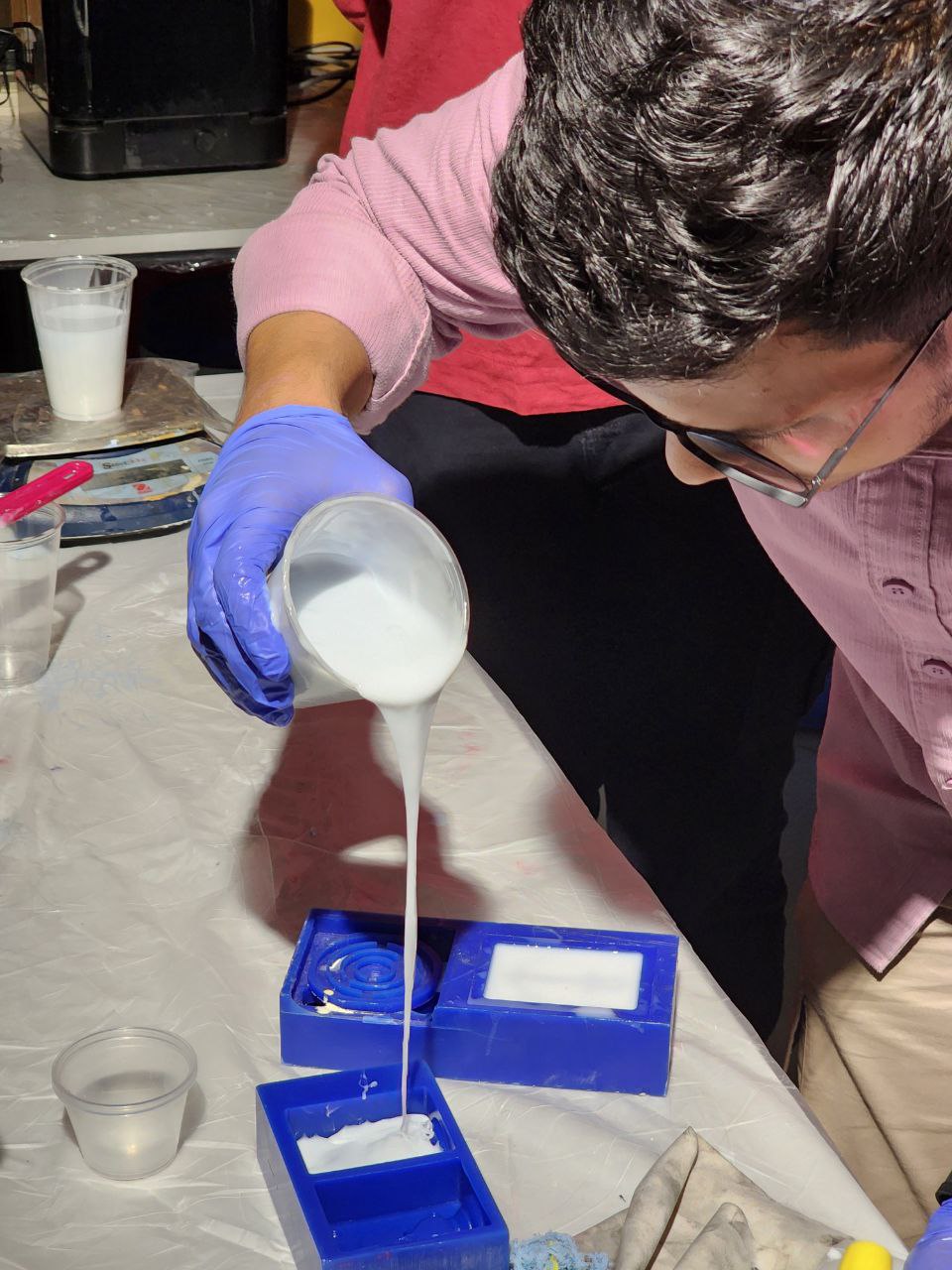
Finally, I poured the resin into the silicone mold. The resin takes around 24 hours to cure.
🚨
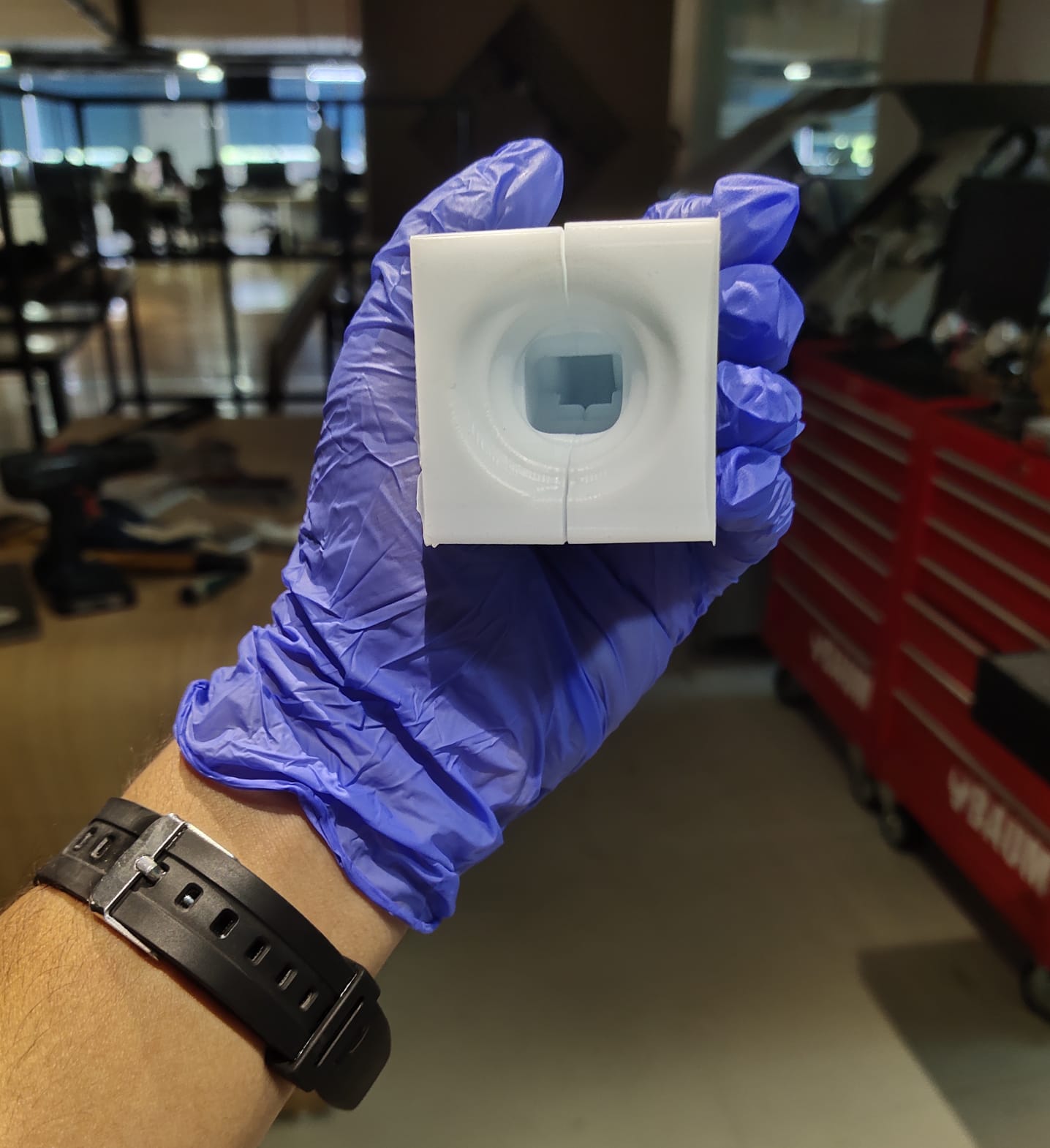
Finally, I got the result 🥹🥹🥹🥹🥹.
🚨
Final Result 🙂
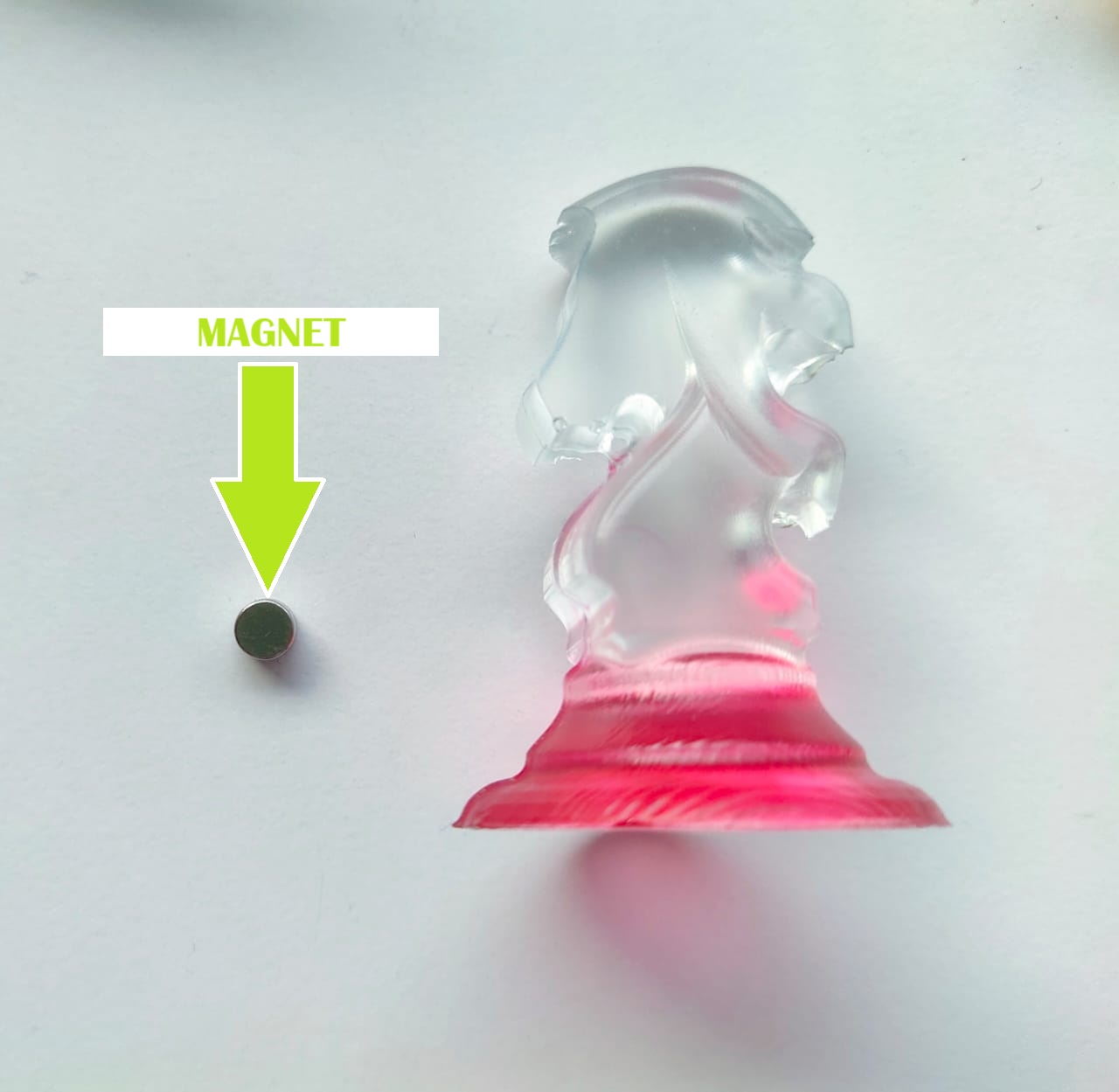
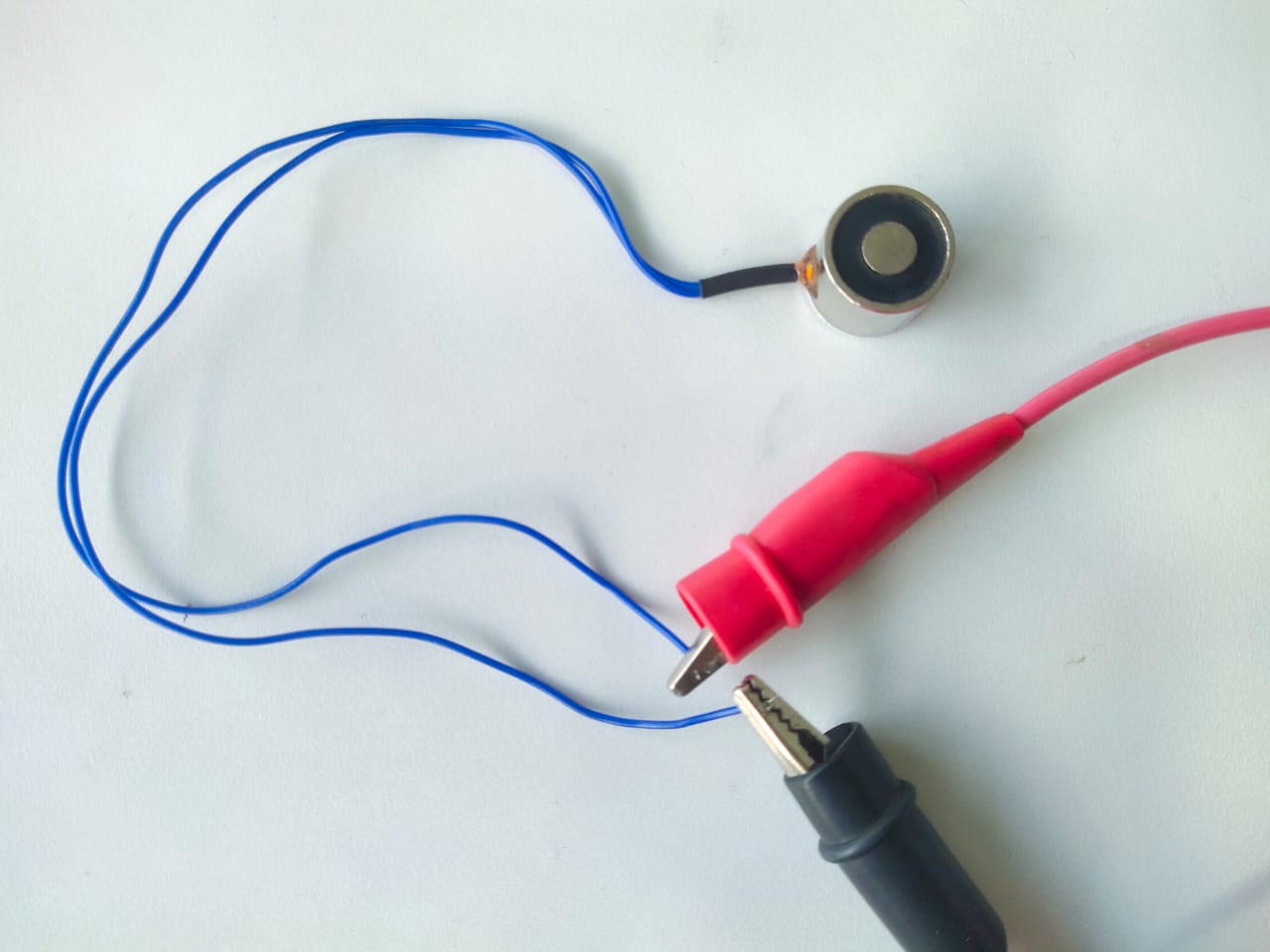
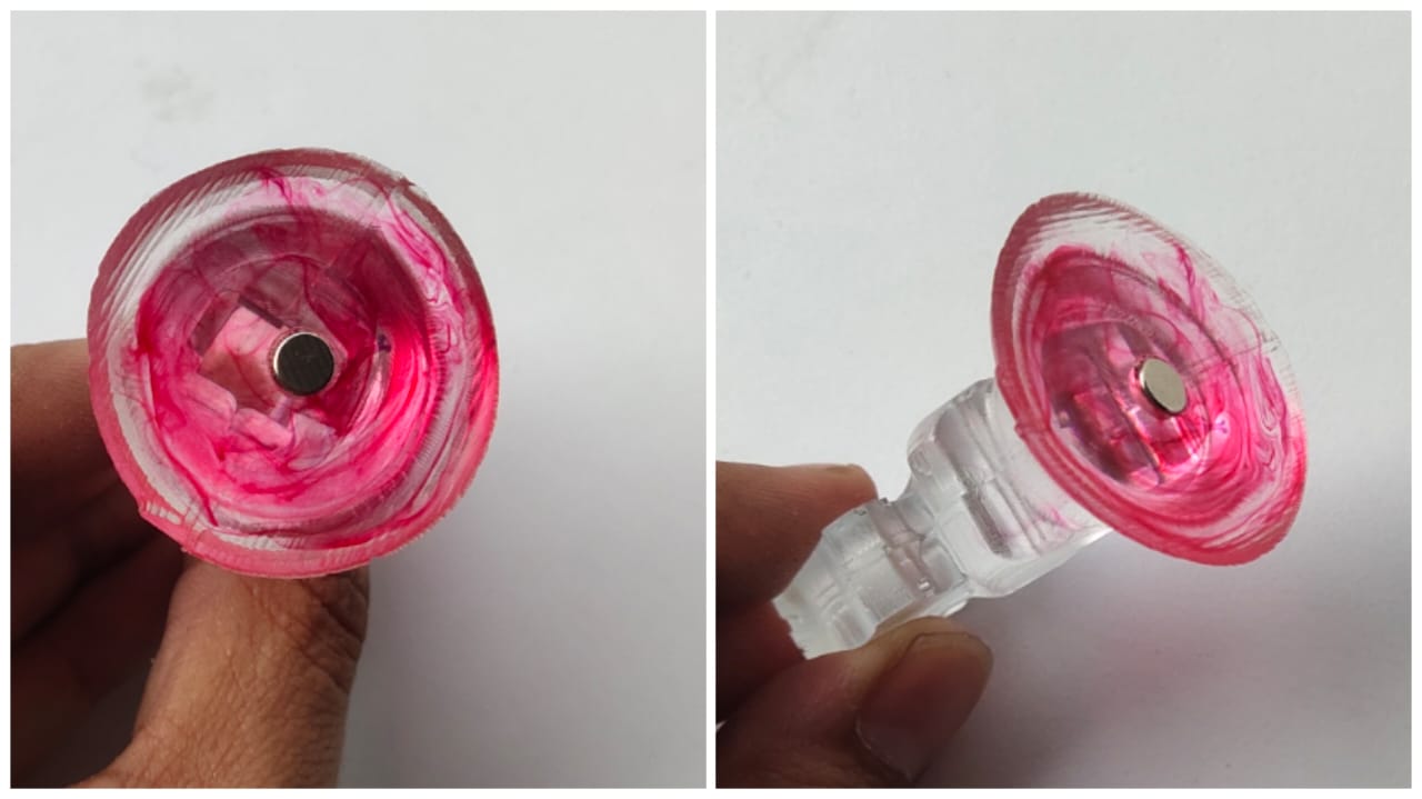
Chess Piece with an Electromagnet
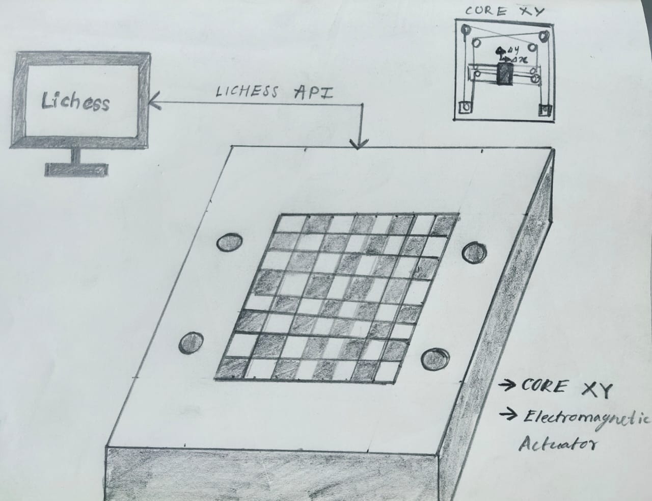
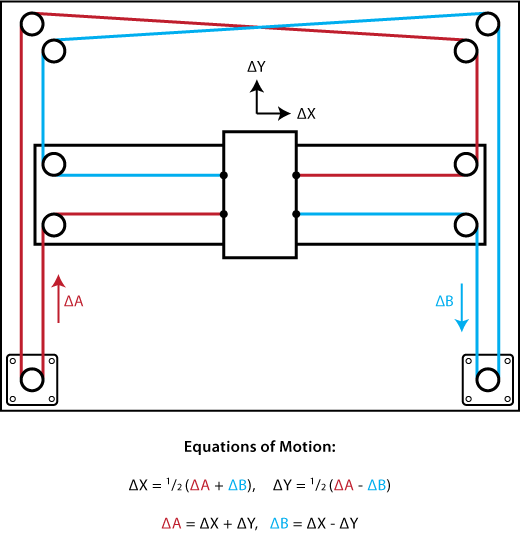
CoreXY Mechanism
CoreXY is a technique used to move the printhead of a 3D printer or the toolhead in CNC machines in the horizontal plane. The advantage of this technique is that the two motors used to perform the movement in the horizontal plane are stationary and do not have to move themselves, which can result in less moving mass.