Individual Assignment
Group Assignment
Table of Contents
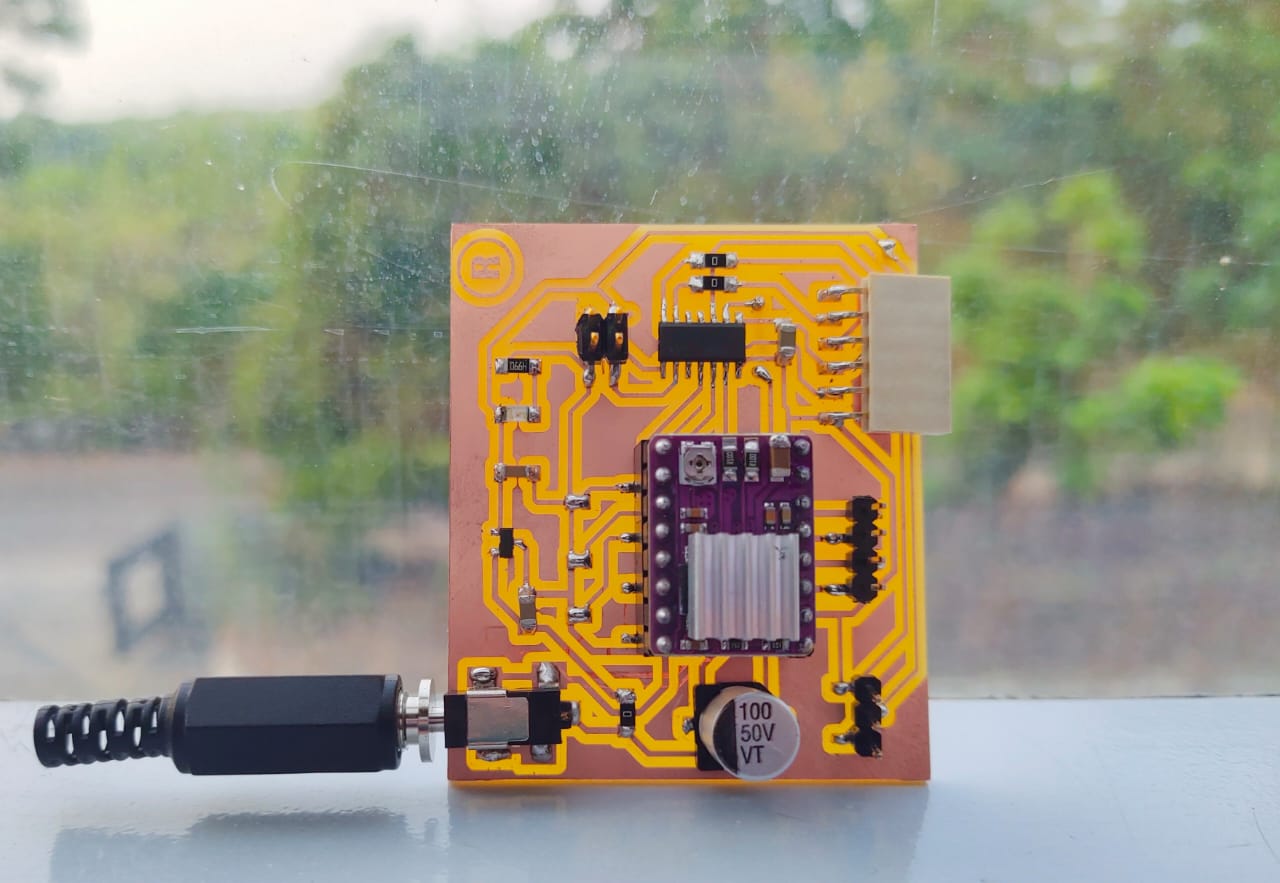
Hero Shot
Week 9 Work Plan
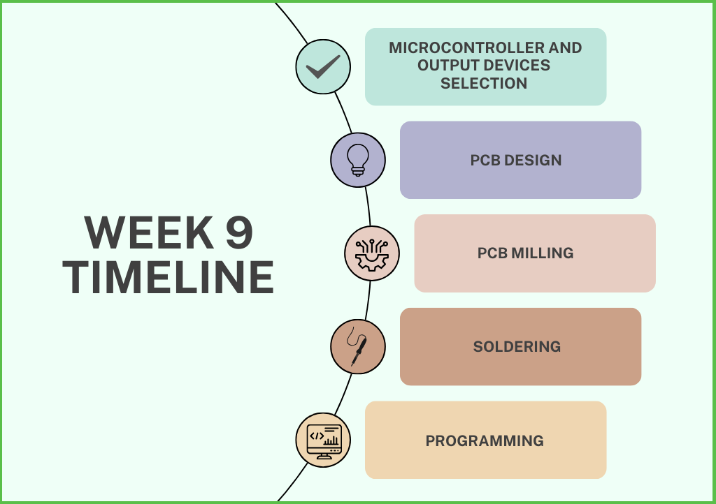

Professor Neil's lecture on Wednesday kicks off this week. The following day, my instructor, suggested that instead of examining a wide range of output devices, I should focus on one or two that I will be using for my final project. After discussing with my instructors, I realized that it would be difficult to finish my first final project idea—a soft robotic fish—in the allotted time. In the end, I chose to pursue my second project idea—a serial robot.
Selecting Output Device
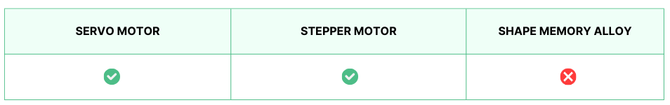
Two essential output devices that I will be employing for my final project are a stepper motor and a servo motor. Since I can use servo motors to drive my robotic arm's end effector, I made the decision to investigate them. There are two different kinds of servo motors available in our inventory: one with a plastic gear and the other with a metal gear. A stepper motor is an option if I need precision. Unipolar, bipolar, and hybrid stepper motors are the three varieties of stepper motors that are in our inventory.
Servo Motor
 https://circuitdigest.com/article/servo-motor-working-and-basics
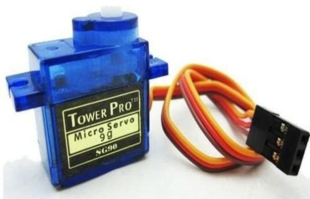
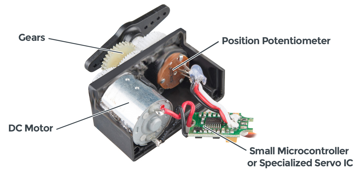
A servo motor is a type of rotary actuator or motor that allows for precise control of angular position, velocity, and acceleration. It consists of a motor coupled with a sensor for feedback, usually a potentiometer or an encoder, which provides information about the motor's current position. This feedback mechanism enables the servo motor to accurately maintain or move to a desired position.
Controlling a Servo
In order to move a servo to a position along its movement arc, or, in the case of continuous rotation servos the speed and direction of the motor, the controller needs to send a precisely timed signal for the servo to interpret. Typical hobby servos expect to see a pulse every 20ms, and the width of this signal determines the position. This width is usually between one and two milliseconds. This type of signal control is frequently referred to as Pulse Width Modulation, abbreviated as PWM. A servo controller will normally be a dedicated piece of hardware that can take inputs from other components like a joystick, potentiometer or sensor feedback to set the control signal for the servo. Other control options include using the PWM-capable pins on a microcontroller to send that signal directly to the servo.
Types of Servos
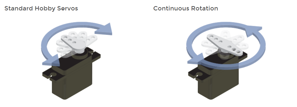
Standard Hobby Servos
A standard hobby or “closed-loop" servo will have a movement range of 90 or 180 degrees. Standard servos provide feedback for the controller to monitor its position on the movement arc over the control signal wire. This allows you to move the servo to precise locations with the right pulse length from your controller.
Continuous Rotation Servos
Continuous rotation or “open-loop" servos do not work like the standard servo. The control signal only controls direction and speed, not position. These enable you to easily control how fast the drive shaft is moving and in which direction it's going, but there's no feedback for position control.
Servo Motor Torque Calculation
Calculating the required torque for a servo motor involves considering several factors related to the load and the mechanical system it's operating in.
Load Torque
This is the torque required to move the load. It depends on factors such as the weight of the load, the distance from the pivot point (radius), and any external forces acting on the load. The formula for load torque (T_load) is:
Where:
F is the force acting on the load (in Newtons, N).
r is the distance from the pivot point to the point where the force is applied (in meters, m).
 https://automaticaddison.com/how-to-determine-what-torque-you-need-for-your-servo-motors/
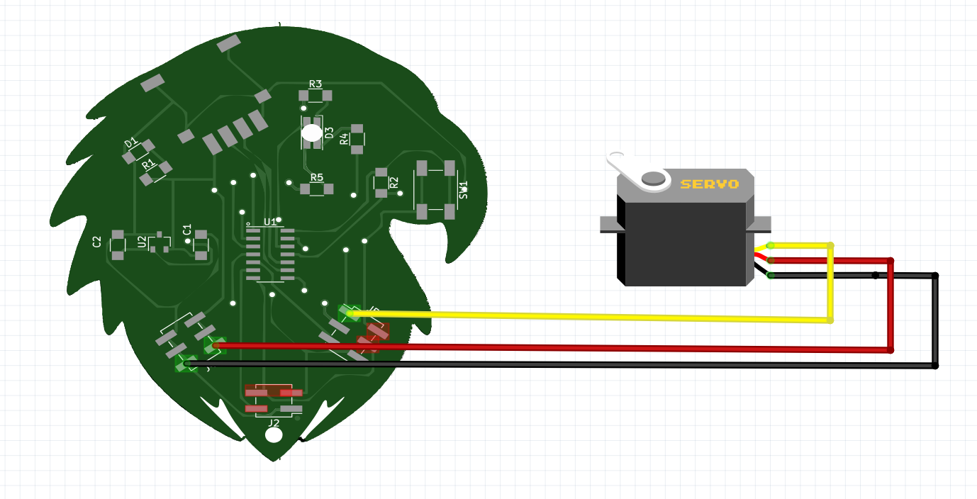
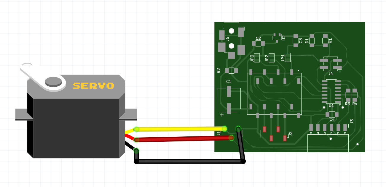
Servo Motor with Eagle Board
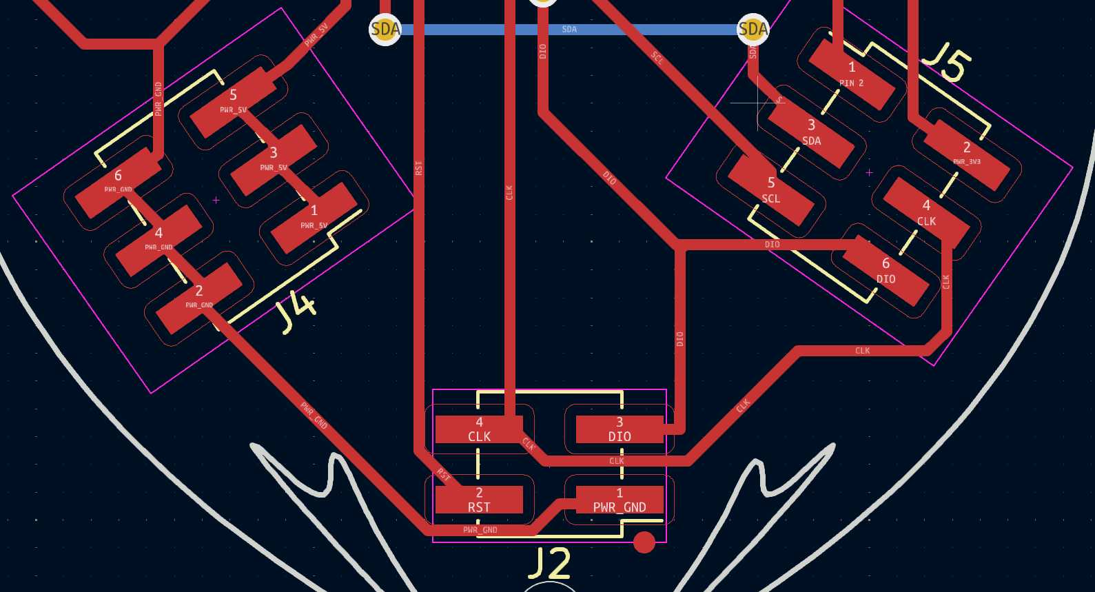
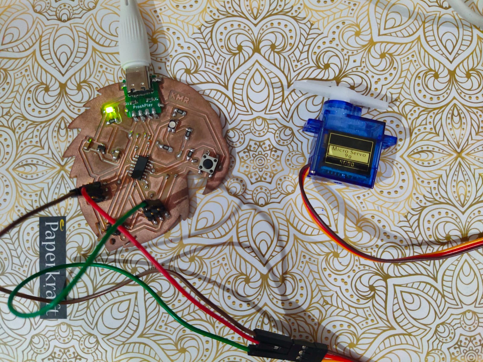
Circuit Connection
Servo Motor VCC ➡️ Eagle Board VCC
Servo Motor GND ➡️ Eagle Board GND
Servo Motor Control Pin ➡️ Eagle Board Pin 2
Servo motor code
#define SERVO_PIN 2  // Define the pin connected to the servo

// Function to initialize the servo motor
void servo_init() {
    pinMode(SERVO_PIN, OUTPUT);
}

// Function to set servo angle
void servo_set_angle(uint8_t angle) {
    // Map angle to pulse width (usually between 1000 to 2000 microseconds)
    // Adjust these values according to your servo motor's specifications
    uint16_t pulse_width = map(angle, 0, 180, 1000, 2000);

    // Generate PWM signal with the calculated pulse width
    // You can use the built-in Arduino Servo library to control the servo
    // For simplicity, we can use a delay loop instead

    // Set pin high for the pulse width duration
    digitalWrite(SERVO_PIN, HIGH);
    delayMicroseconds(pulse_width);

    // Set pin low for the rest of the period
    digitalWrite(SERVO_PIN, LOW);
    delayMicroseconds(20000 - pulse_width); // Assuming 20ms period (50 Hz)
}

void setup() {
    // Initialize the servo
    servo_init();
}

void loop() {
    // Rotate servo to 0 degrees
    servo_set_angle(0);
    delay(1000);
    // Rotate servo to 180 degrees
    servo_set_angle(180);
    delay(1000);
}
Stepper Motor
A stepper motor is a type of electric motor that moves in discrete steps, as opposed to continuous rotation like conventional motors. Each rotation is divided into a certain number of steps, and the motor must be sent a separate pulse for each step. The motor's position can be controlled precisely, without any feedback mechanism, as long as the motor is sized correctly to the task.
 https://www.youtube.com/watch?v=09Mpkjcr0bo
 https://www.youtube.com/watch?v=vxxnPJBxG3M
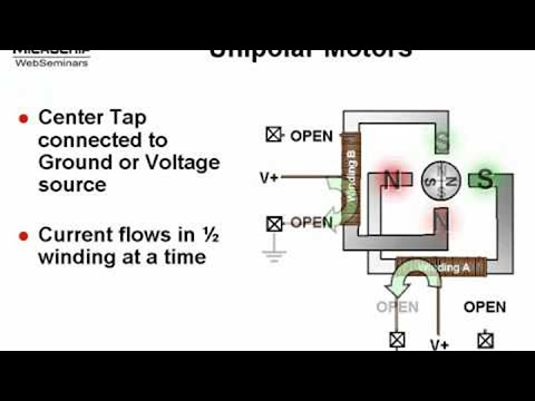 https://www.youtube.com/watch?v=hHe4Fc6uuBs
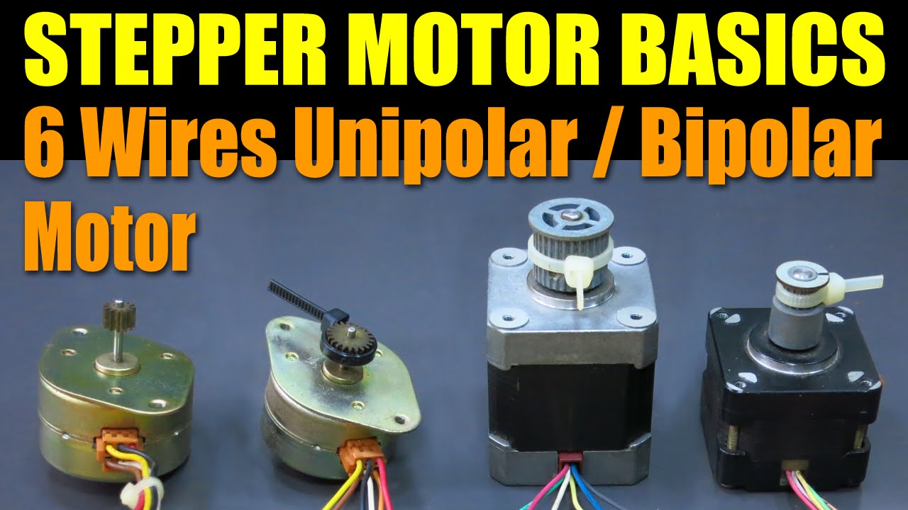
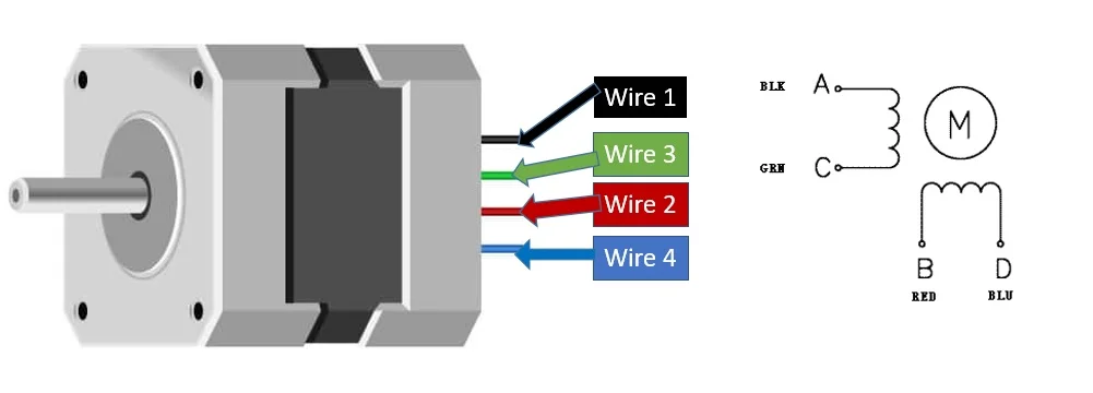
Stepper motors usually come with four, five, six, or eight wires.
Unipolar Stepper Motor
A unipolar stepper motor is a type of stepper motor that operates with a single winding per phase. Each phase has a center tap usually connected to a common power supply. This configuration allows the direction of current flow through the winding to be reversed, changing the magnetic field polarity and allowing for precise control of the motor's position in discrete steps. This makes unipolar stepper motors suitable for applications that require precise positioning and speed control.
Five-wire stepper motor: This is typically a unipolar stepper motor. It has one winding per phase and a common wire.
Bipolar Stepper Motor
A bipolar stepper motor is a type of stepper motor with two coils (phases) that are driven by a bipolar drive circuit. This means the electric current can flow in both directions, allowing the motor to have a higher torque at high speeds compared to a unipolar stepper motor. The two phases are used to create a magnetic field, which rotates the motor shaft to precise positions. Unlike unipolar stepper motors, bipolar motors only have one winding per phase, meaning they require more complex control circuitry.
Four-wire stepper motor: This is usually a bipolar stepper motor. It has two windings and no common wire.
Hybrid Stepper Motor
Hybrid Stepper Motors are a type of stepper motor that combine the best features of both unipolar and bipolar stepper motors. They are designed with a rotor that is magnetized and has teeth, which align with the teeth on the stator to provide better positioning and torque than either unipolar or bipolar stepper motors alone. The hybrid design allows for greater precision and performance.
Six-wire stepper motor: This could be a unipolar or a bipolar stepper motor. It has two windings per phase and a center tap on each winding, which is used for unipolar operation and ignored for bipolar operation.
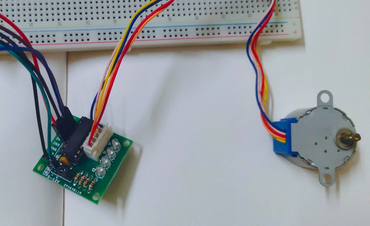
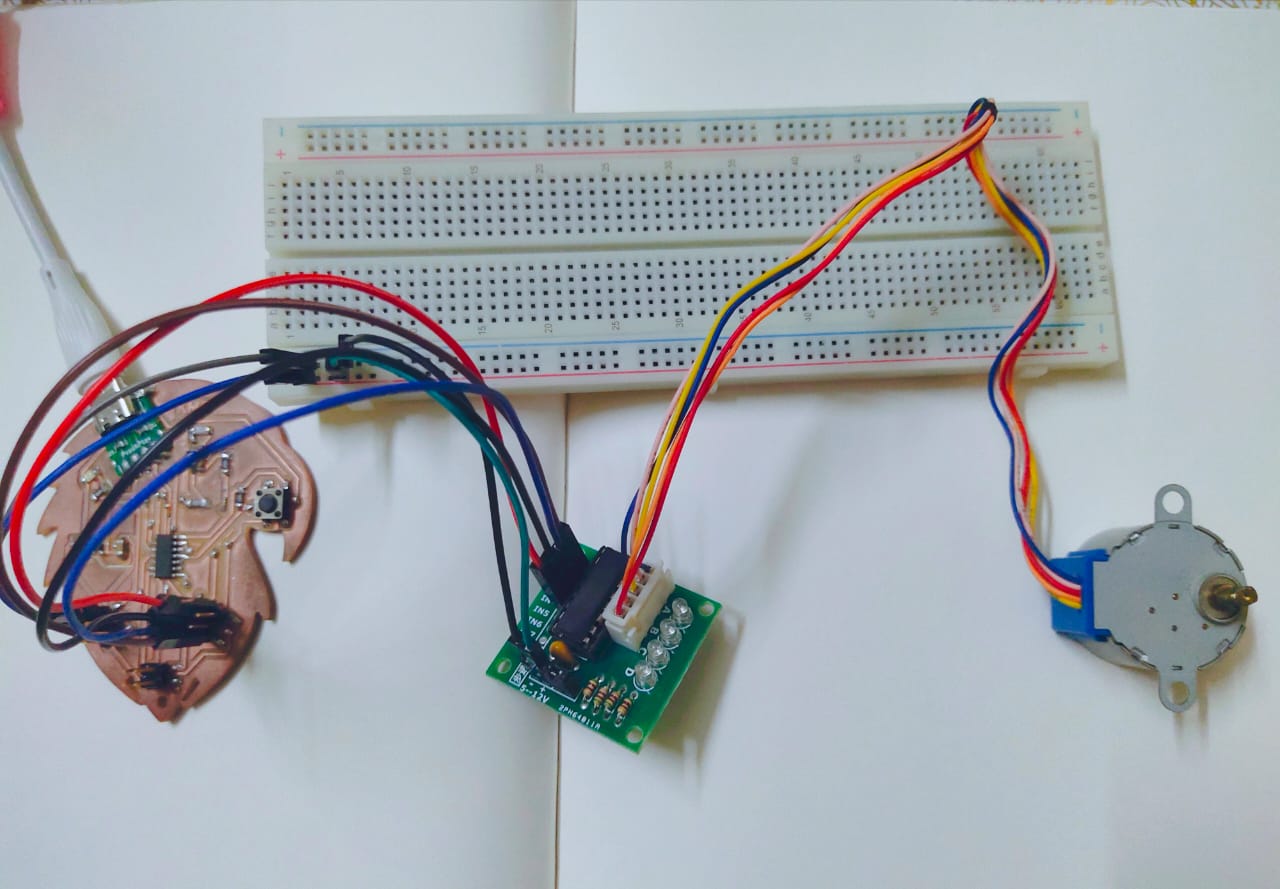
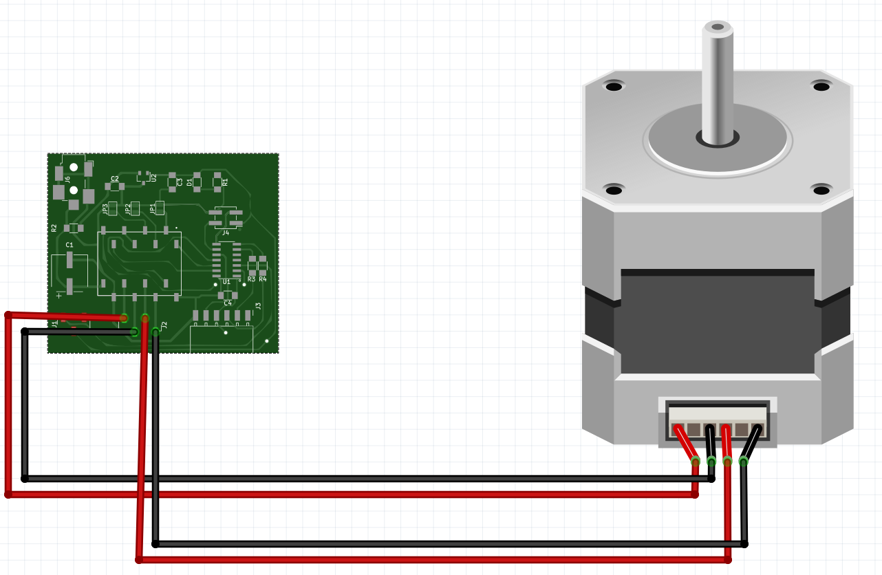
Unipolar Stepper Motor with Eagle Board
Stepper motor code
#define STEPPER_PIN1 2  // Define pin 1 for stepper motor
#define STEPPER_PIN2 14  // Define pin 2 for stepper motor
#define STEPPER_PIN3 15  // Define pin 3 for stepper motor
#define STEPPER_PIN4 31  // Define pin 4 for stepper motor

#define STEPS_PER_REVOLUTION 200  // Number of steps per revolution of your stepper motor

// Define the sequence of steps for full stepping mode
const int step_sequence[4][4] = {
    {1, 0, 0, 1},
    {1, 1, 0, 0},
    {0, 1, 1, 0},
    {0, 0, 1, 1}
};

// Function to initialize stepper motor pins
void stepper_init() {
    pinMode(STEPPER_PIN1, OUTPUT);
    pinMode(STEPPER_PIN2, OUTPUT);
    pinMode(STEPPER_PIN3, OUTPUT);
    pinMode(STEPPER_PIN4, OUTPUT);
}

// Function to step the motor by one step
void stepper_step(int step) {
    for (int i = 0; i < 4; i++) {
        digitalWrite(STEPPER_PIN1, step_sequence[step][0]);
        digitalWrite(STEPPER_PIN2, step_sequence[step][1]);
        digitalWrite(STEPPER_PIN3, step_sequence[step][2]);
        digitalWrite(STEPPER_PIN4, step_sequence[step][3]);
        delay(2); // Adjust delay as needed for your motor speed
    }
}

// Function to rotate the stepper motor by a specified number of steps
void stepper_rotate(int steps, bool direction) {
    // Direction: true = clockwise, false = counterclockwise
    for (int i = 0; i < abs(steps); i++) {
        if (direction)
            stepper_step(i % 4);
        else
            stepper_step((4 - i % 4) % 4);
    }
}

void setup() {
    // Initialize stepper motor
    stepper_init();
}

void loop() {
    // Rotate stepper motor 360 degrees clockwise
    stepper_rotate(STEPS_PER_REVOLUTION, true);
    delay(1000);

    // Rotate stepper motor 360 degrees counterclockwise
    stepper_rotate(STEPS_PER_REVOLUTION, false);
    delay(1000);
}
Designing a New Board
Selecting Motor
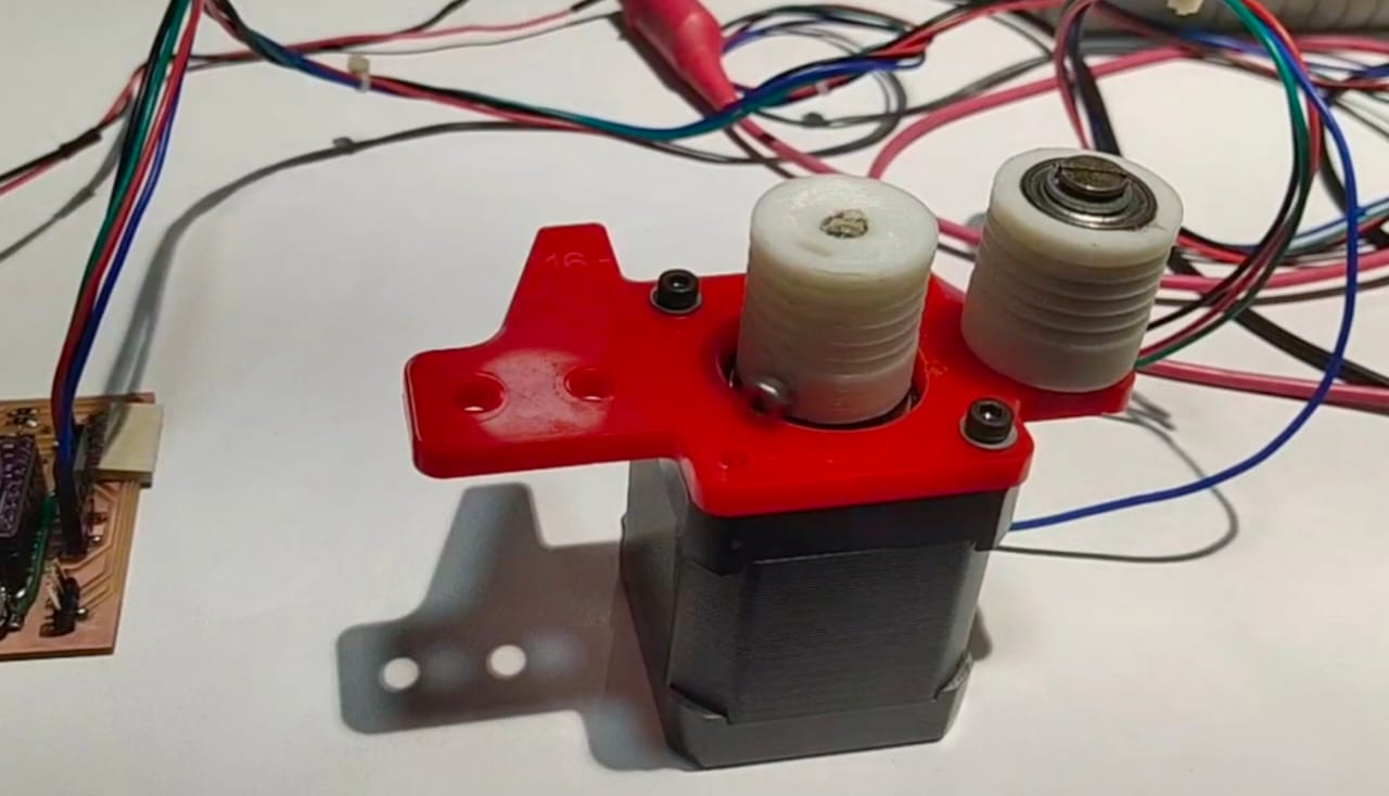
NEMA 17 Stepper Motor
 https://robocraze.com/blogs/post/nema-17-the-high-torque-stepper-motor-working-principle
A NEMA17 stepper motor is a stepper motor with a 1.7 x 1.7 inch (43.2 x 43.2 mm) faceplate. This motor is commonly used in many machines such as 3D printers and CNC machines, thanks to its compact size and reliable performance. The Nema 17 stepper motor operates by dividing a full rotation into a large number of steps, which allows for precise control of rotation, making it ideal for applications where precise positioning is required.
NEMA 17 is a hybrid stepper motor, but it comes with 4 pins as well.
Selecting Motor Driver
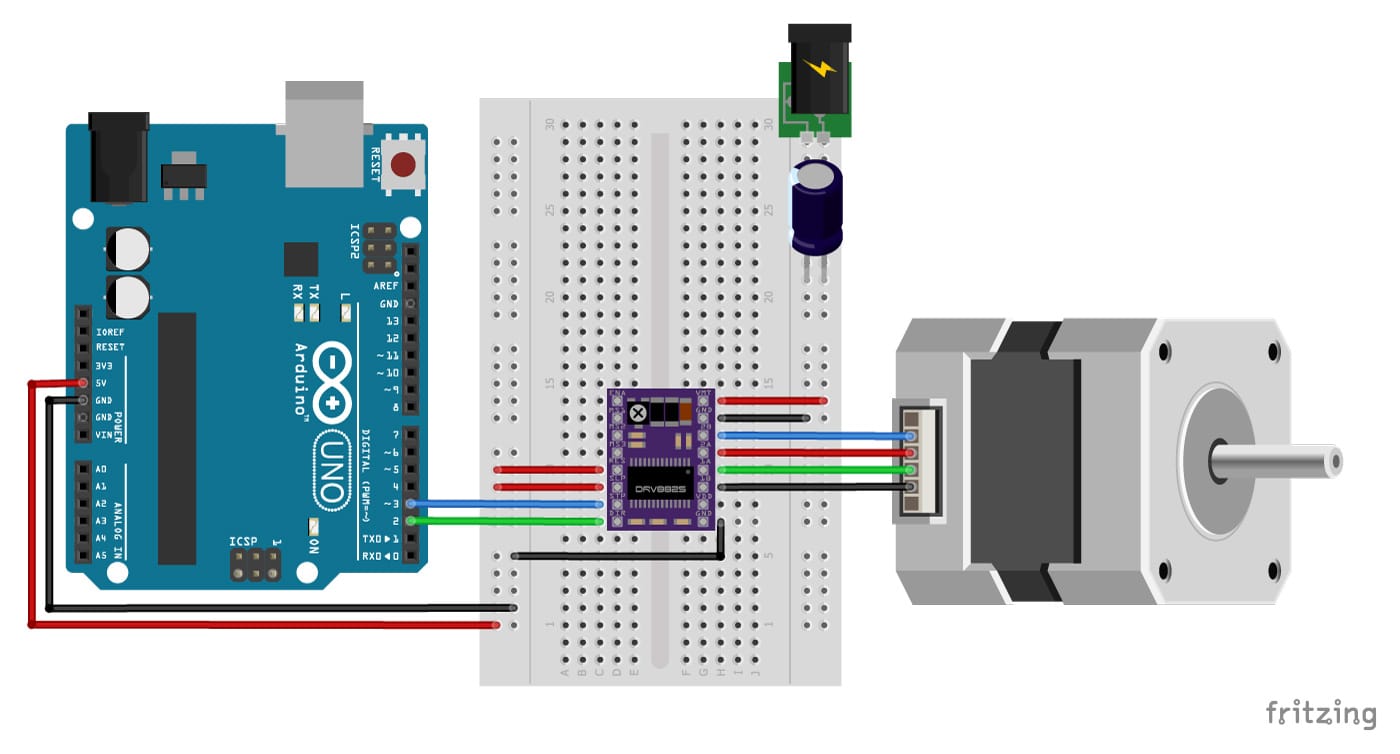
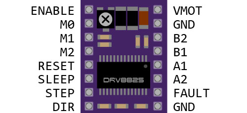
DRV8825 Motor Driver
The DRV8825 is a motor driver that is commonly used to control bipolar stepper motors. It is characterized by its high output capacity and ability to drive up to 2.5A of current from each output. The DRV8825 offers features such as adjustable current limiting, overcurrent and overtemperature protection, and six microstep resolutions (down to 1/32-step). It also has a simple step and direction control interface.
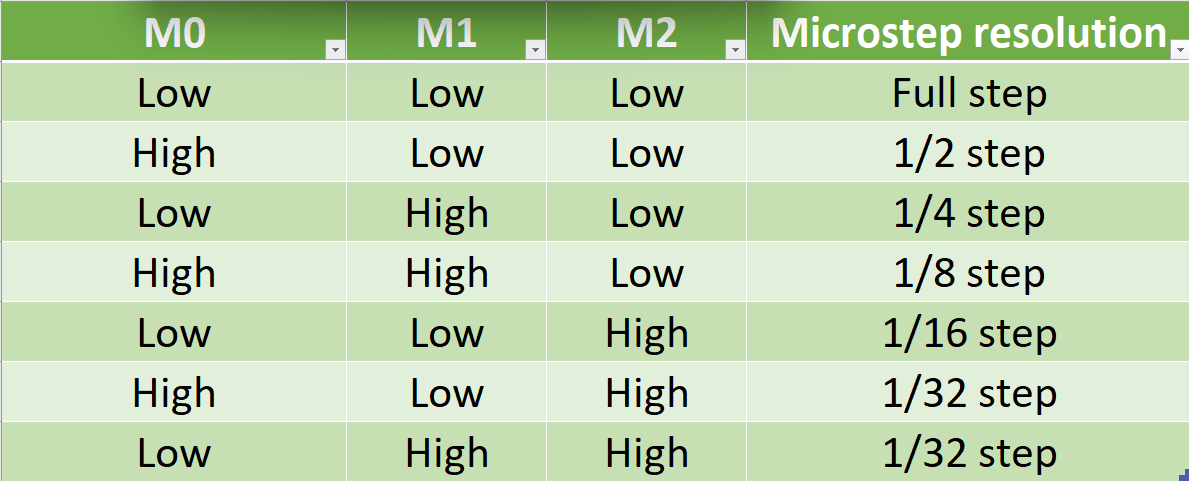
Microstep settings
Microstepping is a method of controlling stepper motors, typically used to achieve higher resolution or smoother motion at low speeds. In the case of the DRV8825 driver, it supports up to 1/32 microsteps. This means that for every single step the motor takes, the DRV8825 can make it take up to 32 microsteps instead, resulting in smoother and more precise movement.
Stepper motors typically have a step size of 1.8° or 200 steps per revolution, this refers to full steps. A microstepping driver such as the DRV8825 allows higher resolutions by allowing intermediate step locations.
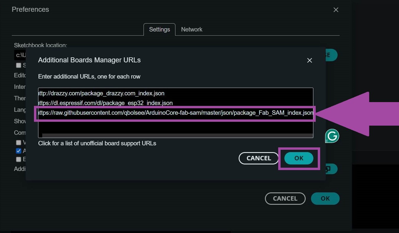
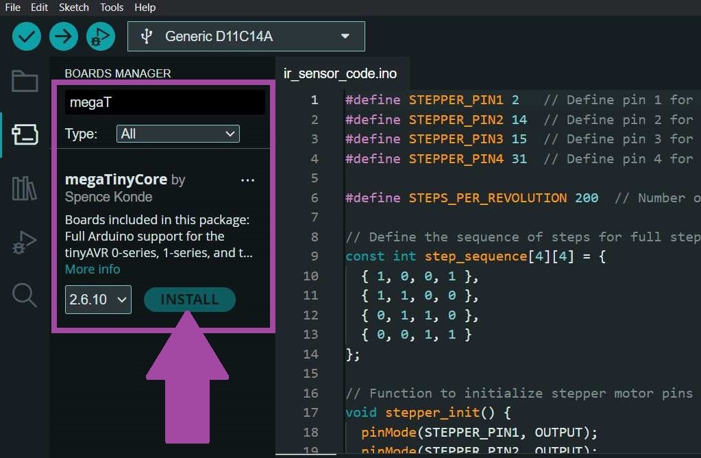
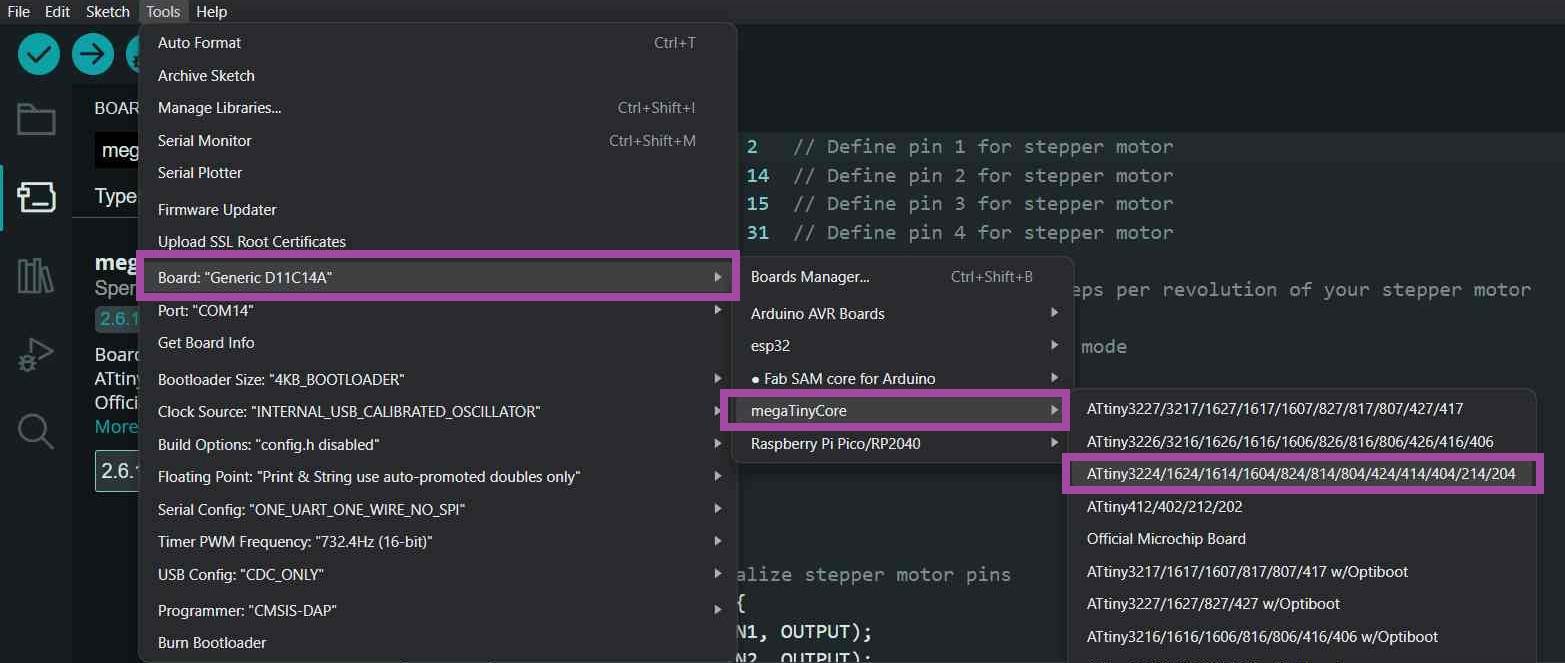
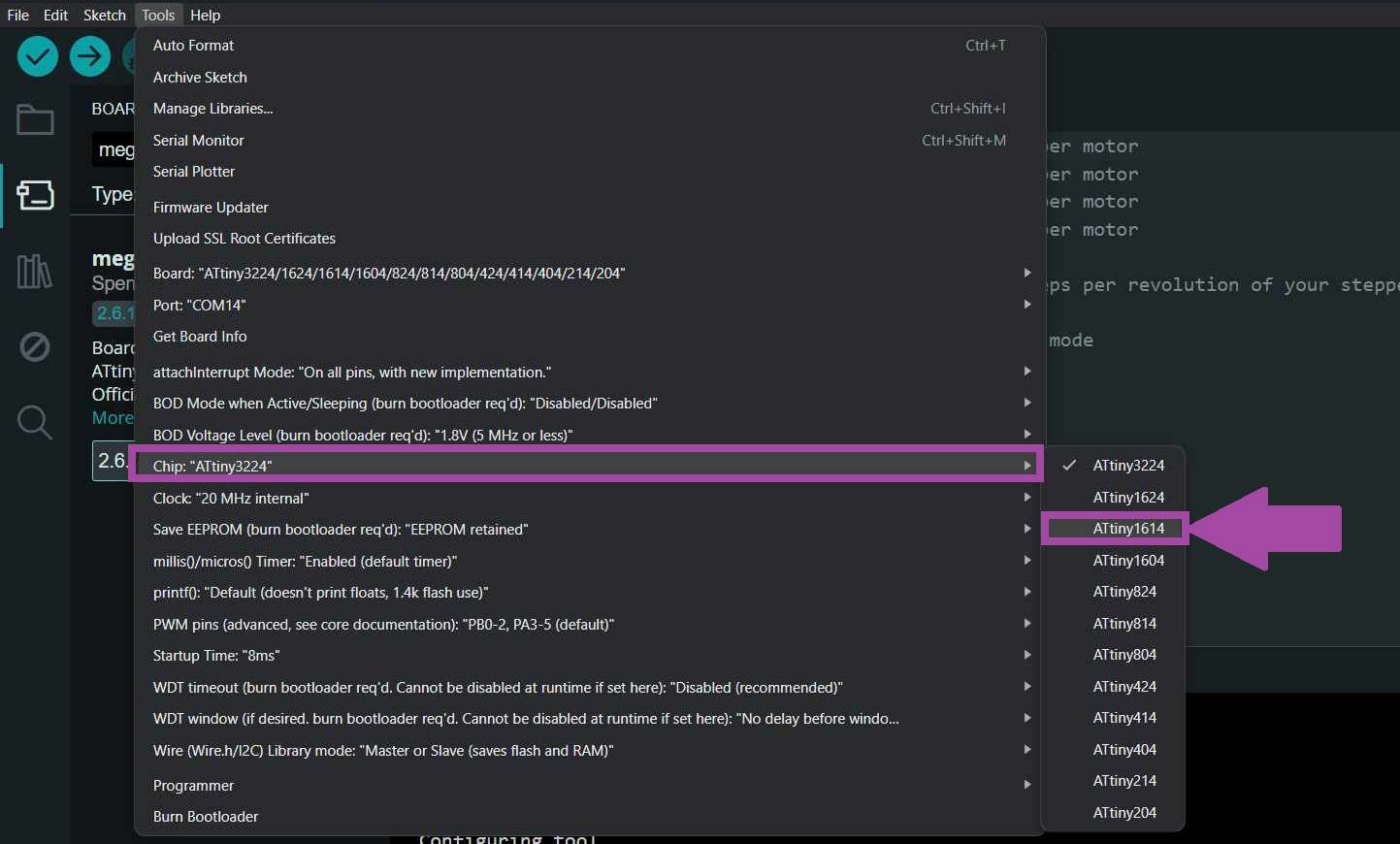
Selecting Microcontroller
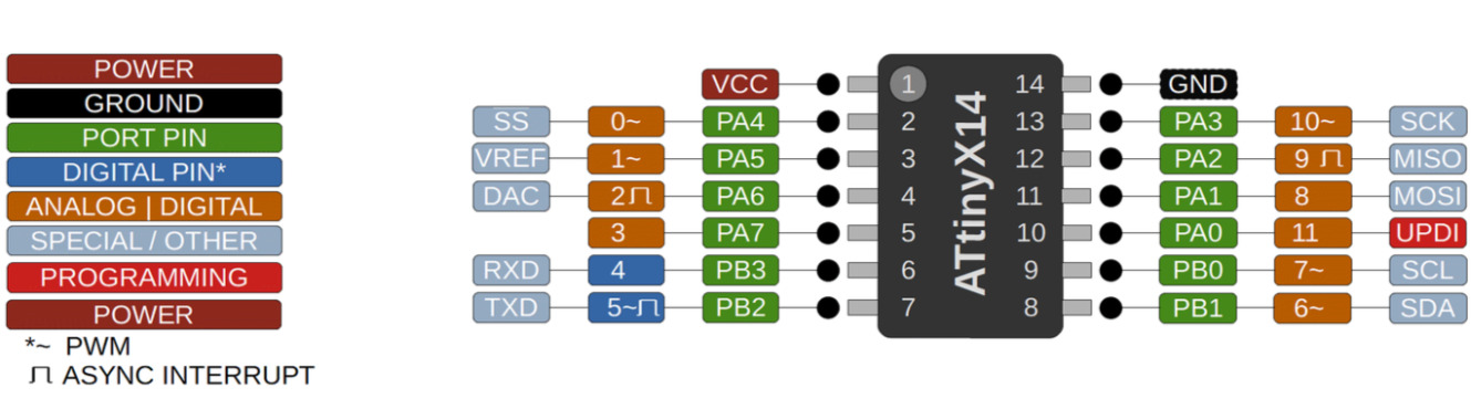
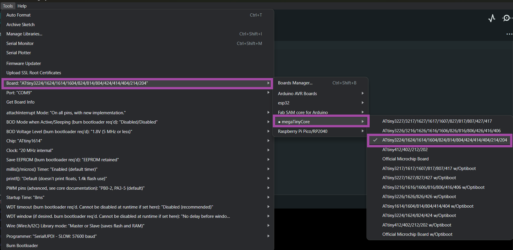
ATtiny1614
The ATtiny1614 is a high-performance, low-power 8-bit AVR RISC-based microcontroller that combines 16KB ISP flash memory, 256B EEPROM, 2KB SRAM, and operates up to 20 MHz. It offers a broad range of features including 18 general purpose I/O lines, 32 general purpose working registers, three flexible timer/counters with compare modes, internal and external interrupts, a serial programmable USART, a byte-oriented 2-wire serial interface, a 10-bit ADC with 10 channels, a programmable watchdog timer with internal oscillator, and five software-selectable power saving modes.
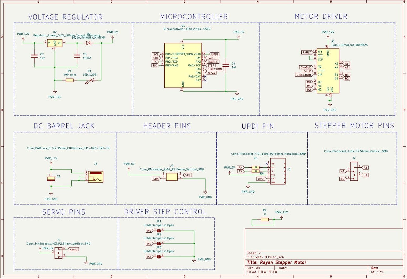
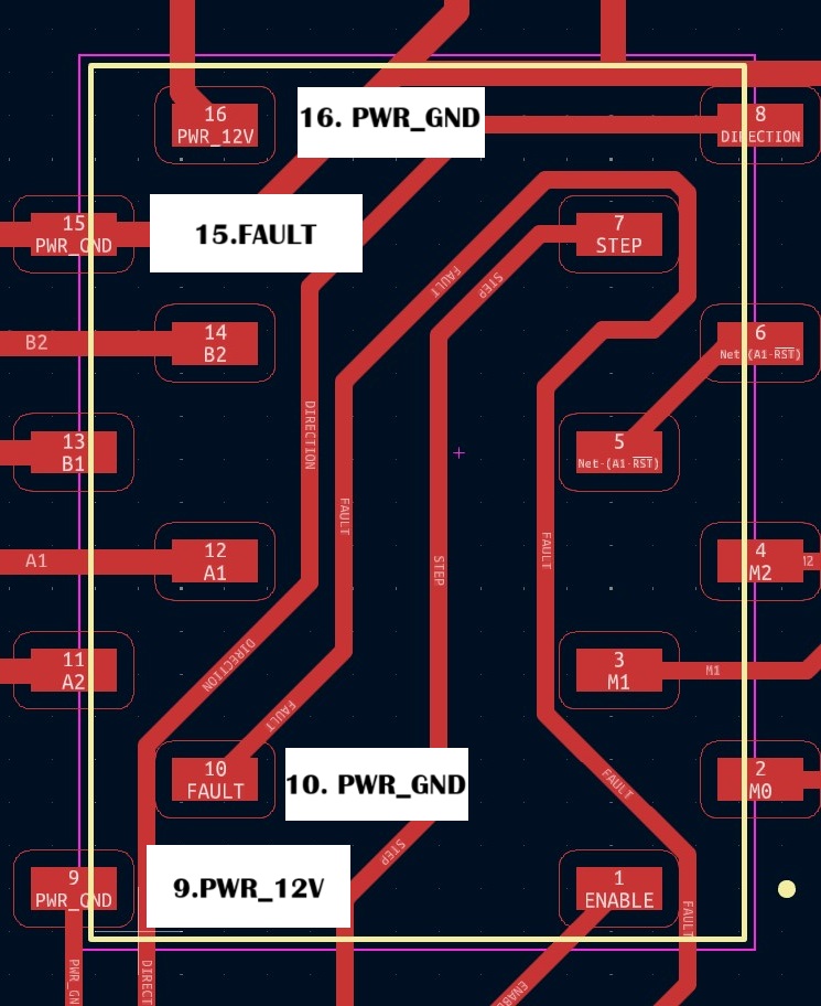
Schematic in KiCAD
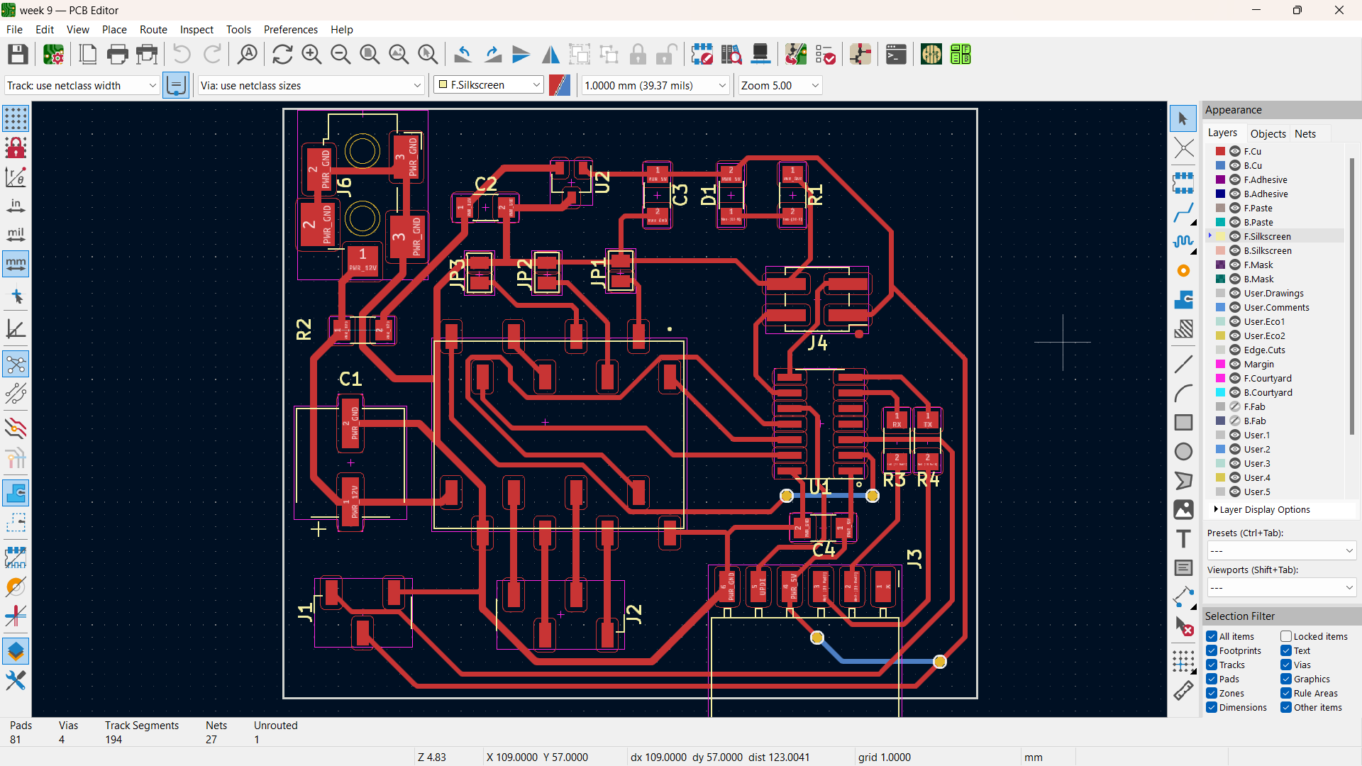
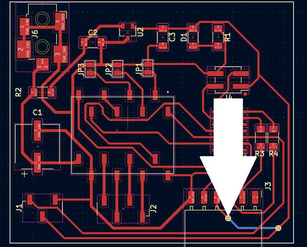
PCB Layout in KiCAD
PCB Trace Width Calculator
A PCB Trace Width Calculator is a tool used in the design of printed circuit boards (PCBs). It calculates the appropriate trace width for a specified current, and vice versa, based on the material properties and thickness of the PCB. This tool helps designers ensure that the PCB can handle the expected electrical load, thereby preventing overheating and potential failure of the board.
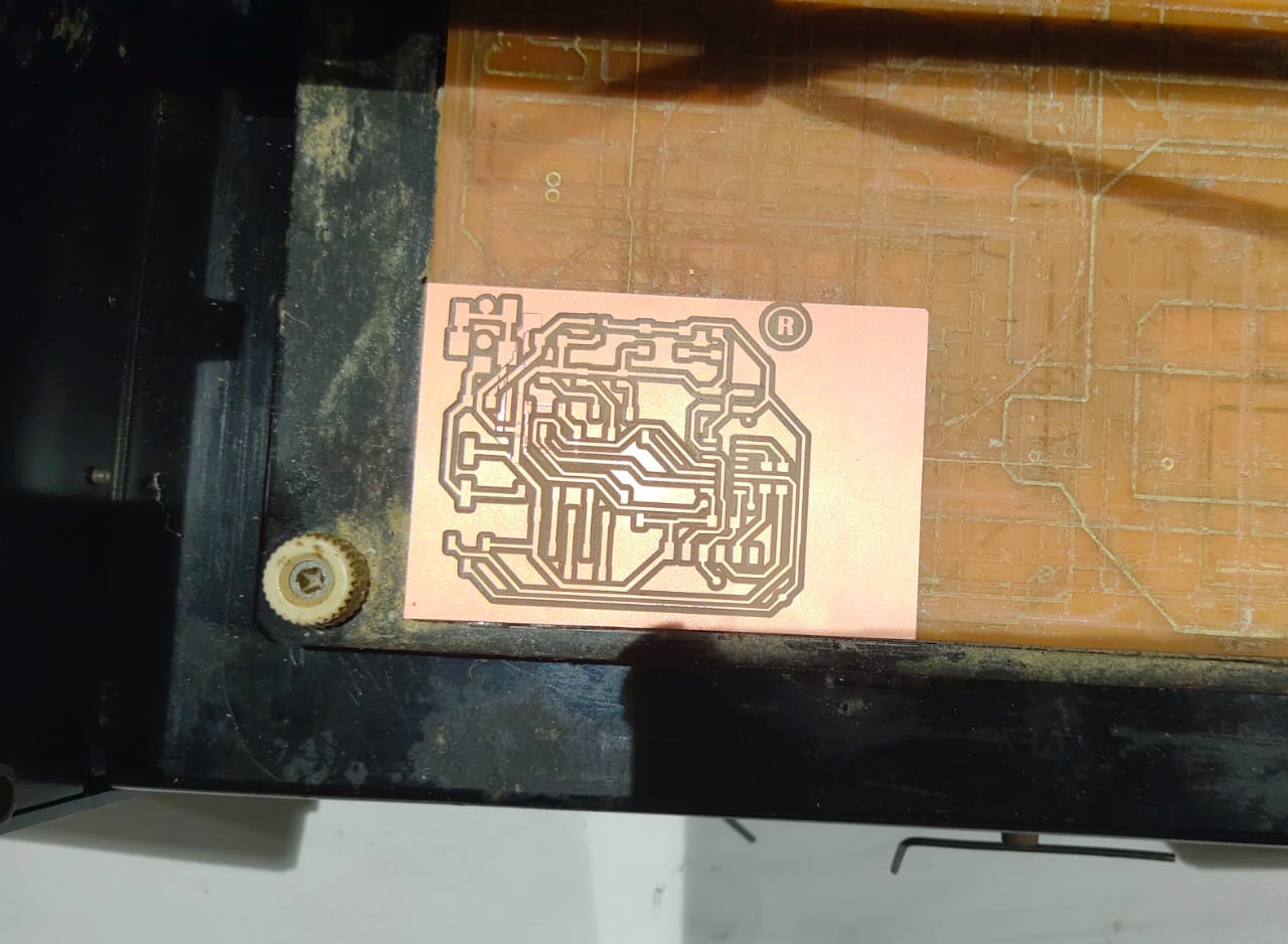
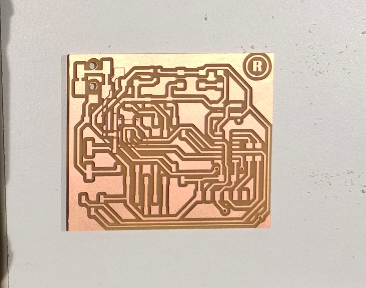
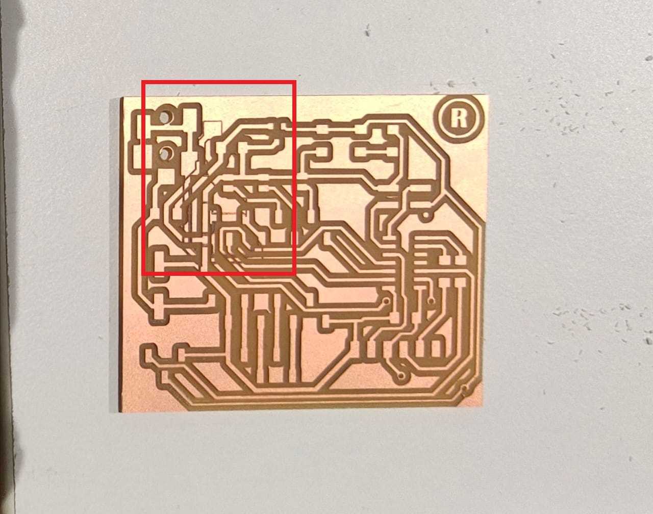
PCB Milling
 https://gerber2png.fablabkerala.in/
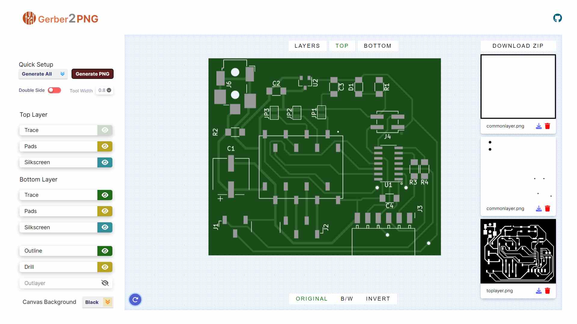
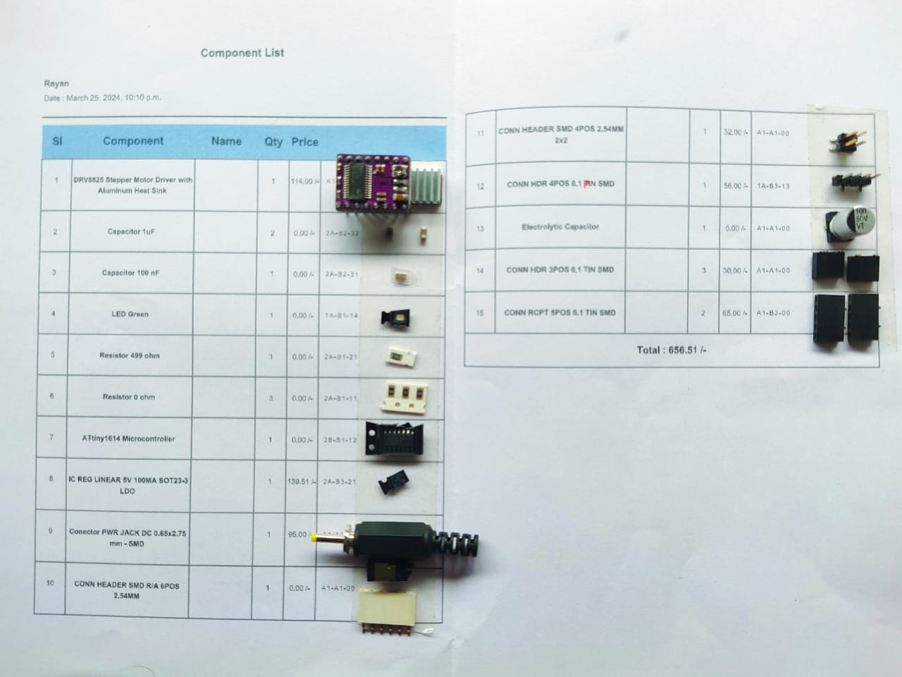
Bill of Materials
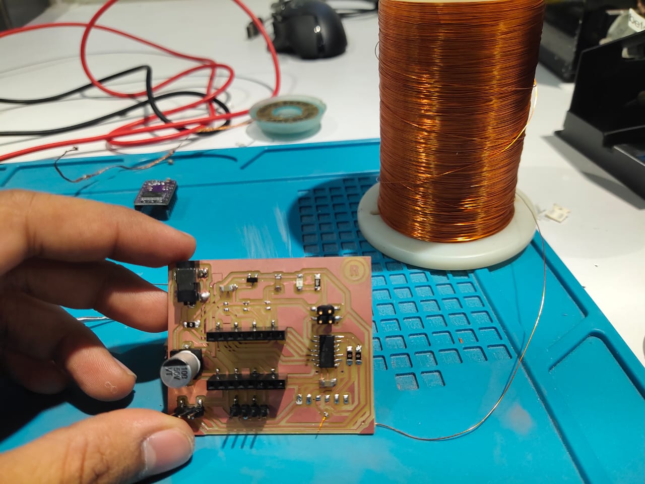
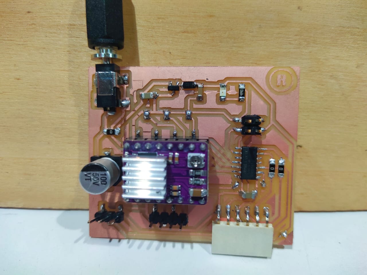
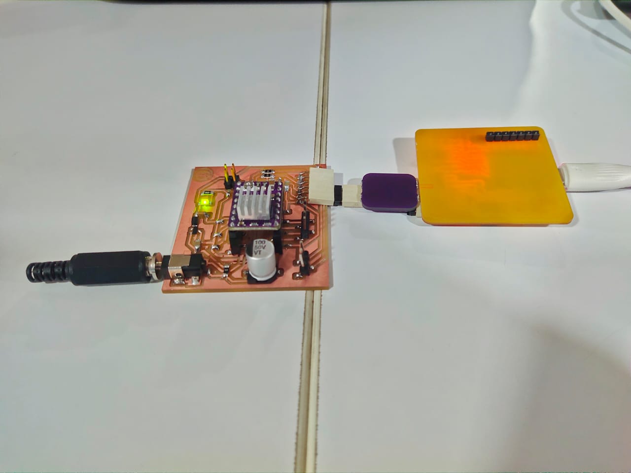
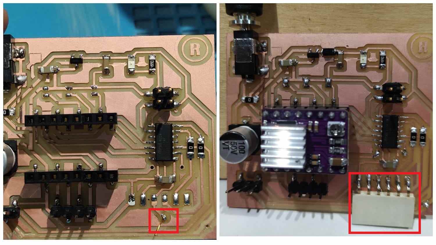
Soldering the Board


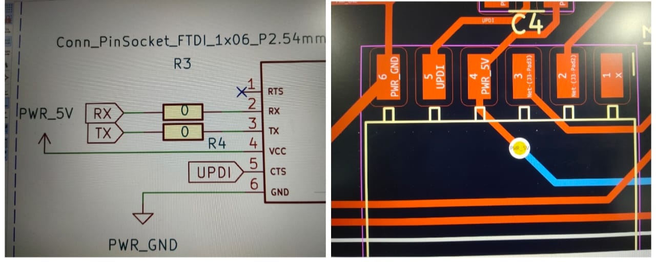
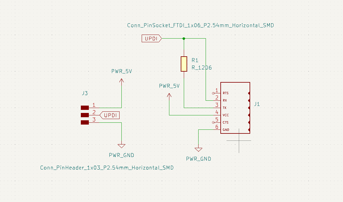
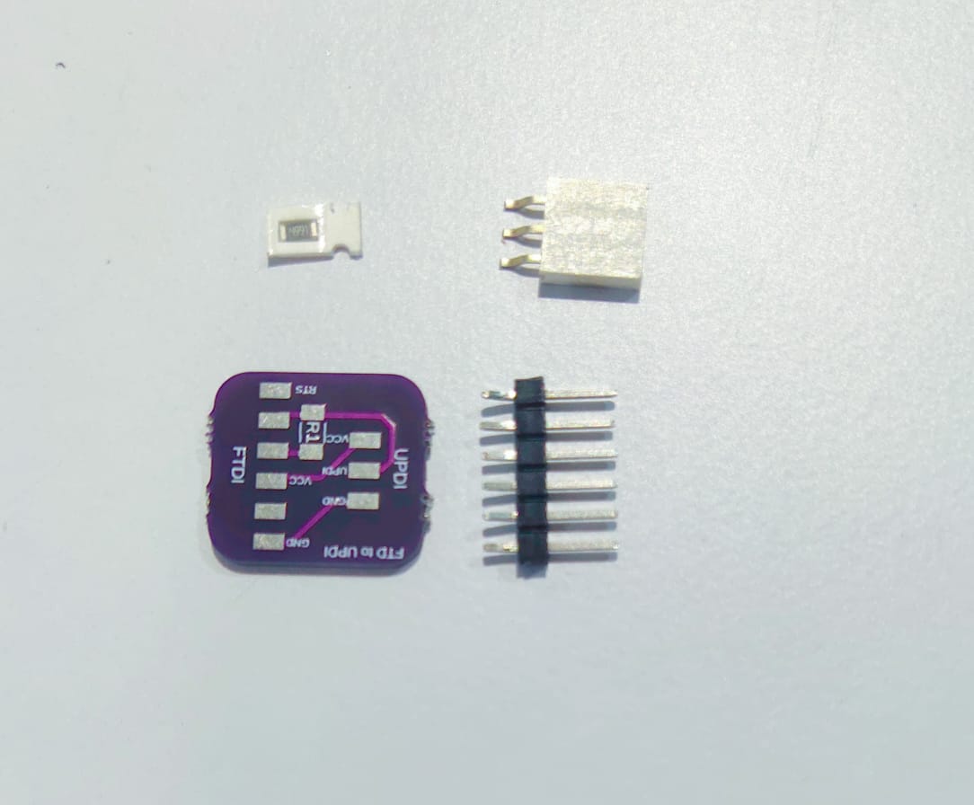
FTDI to UPDI Converter
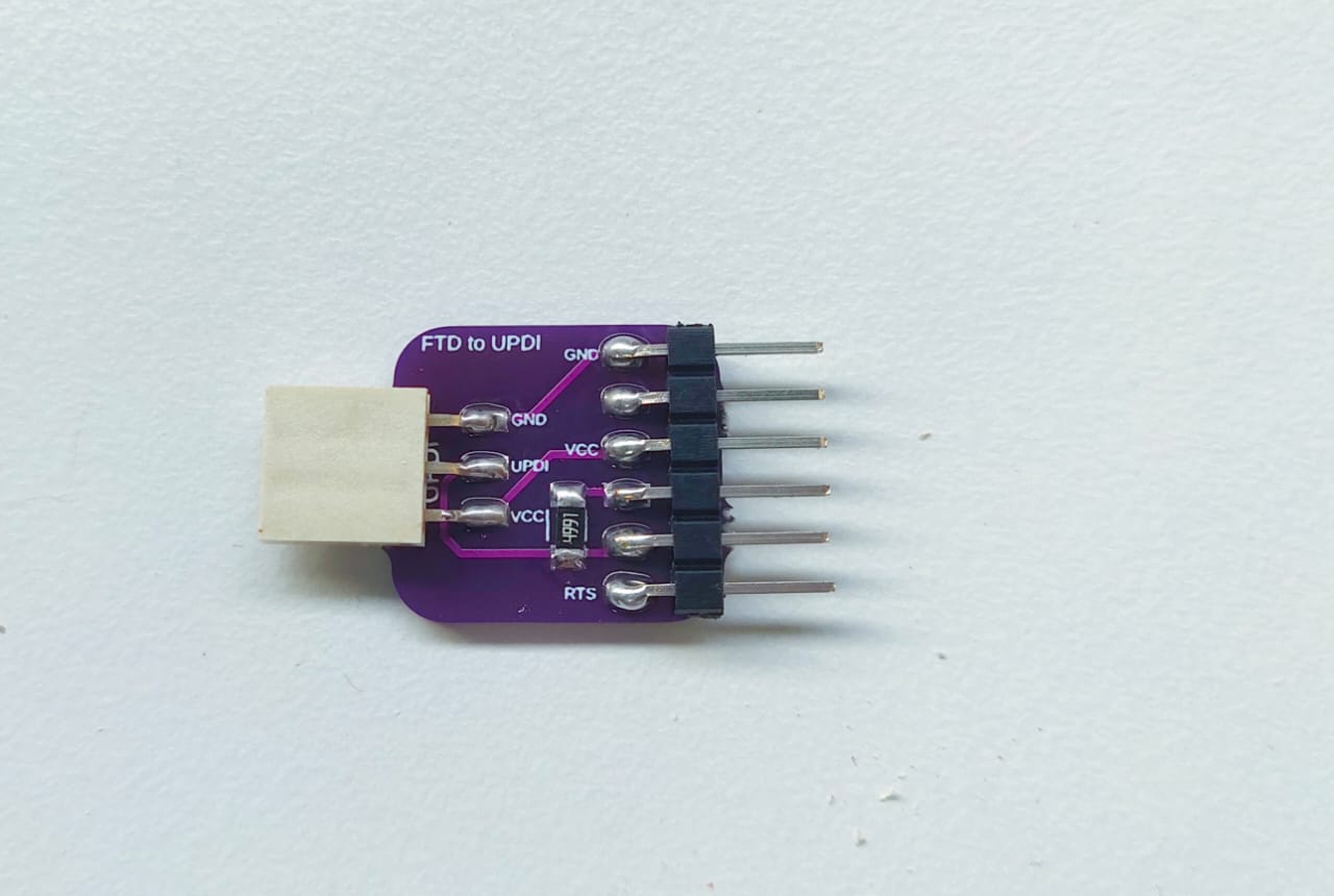
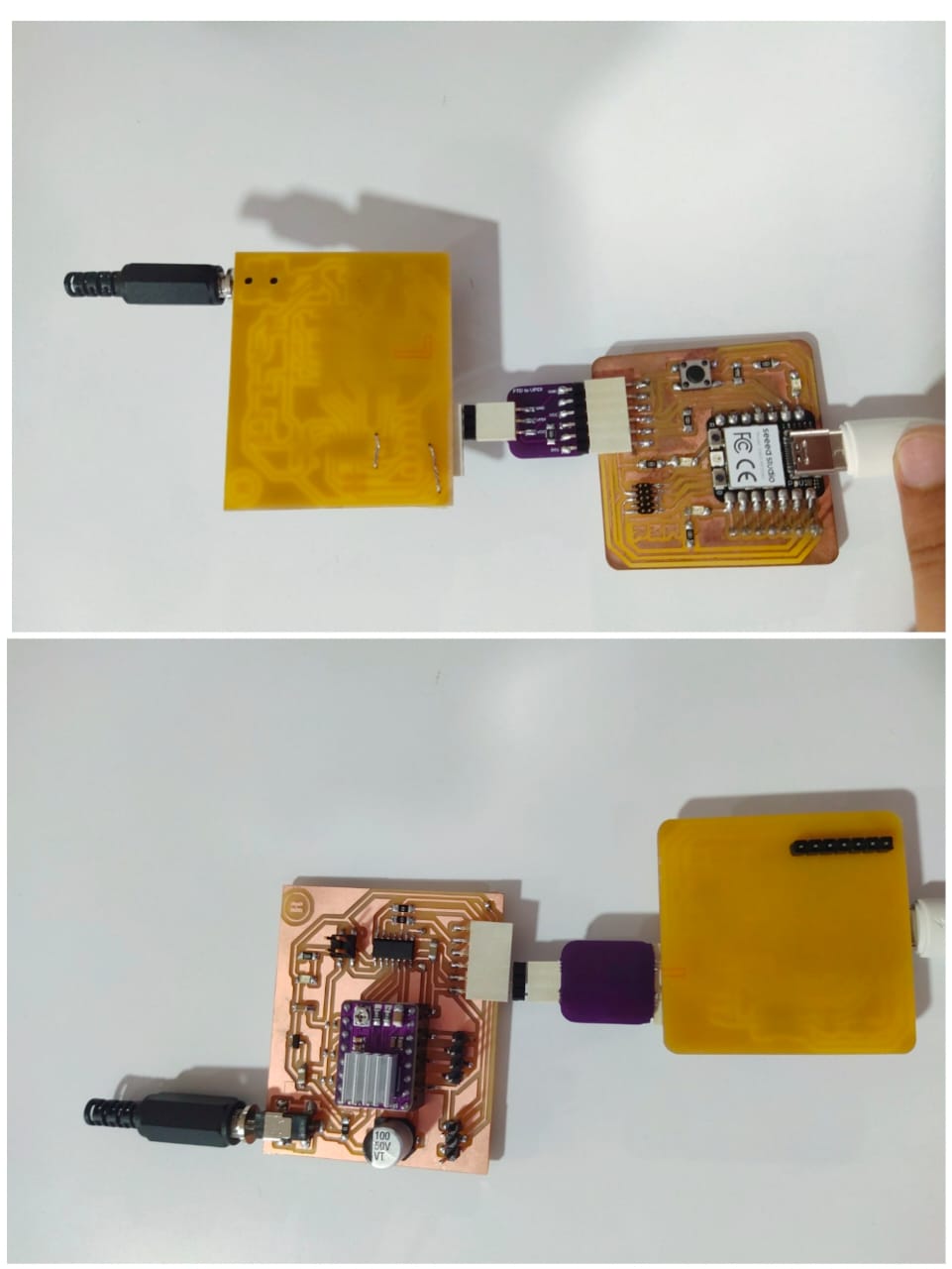
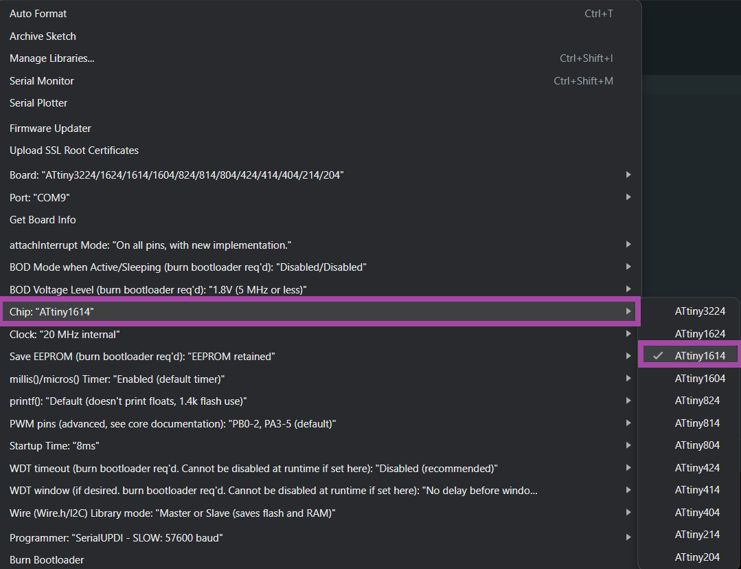
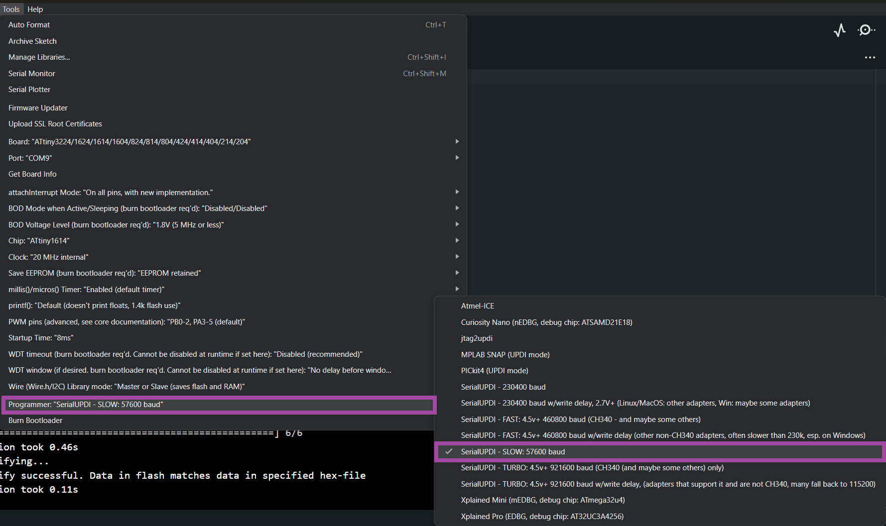
Programming ATtiny 1614 using UPDI
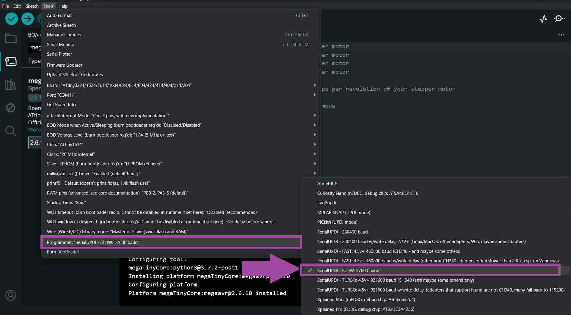
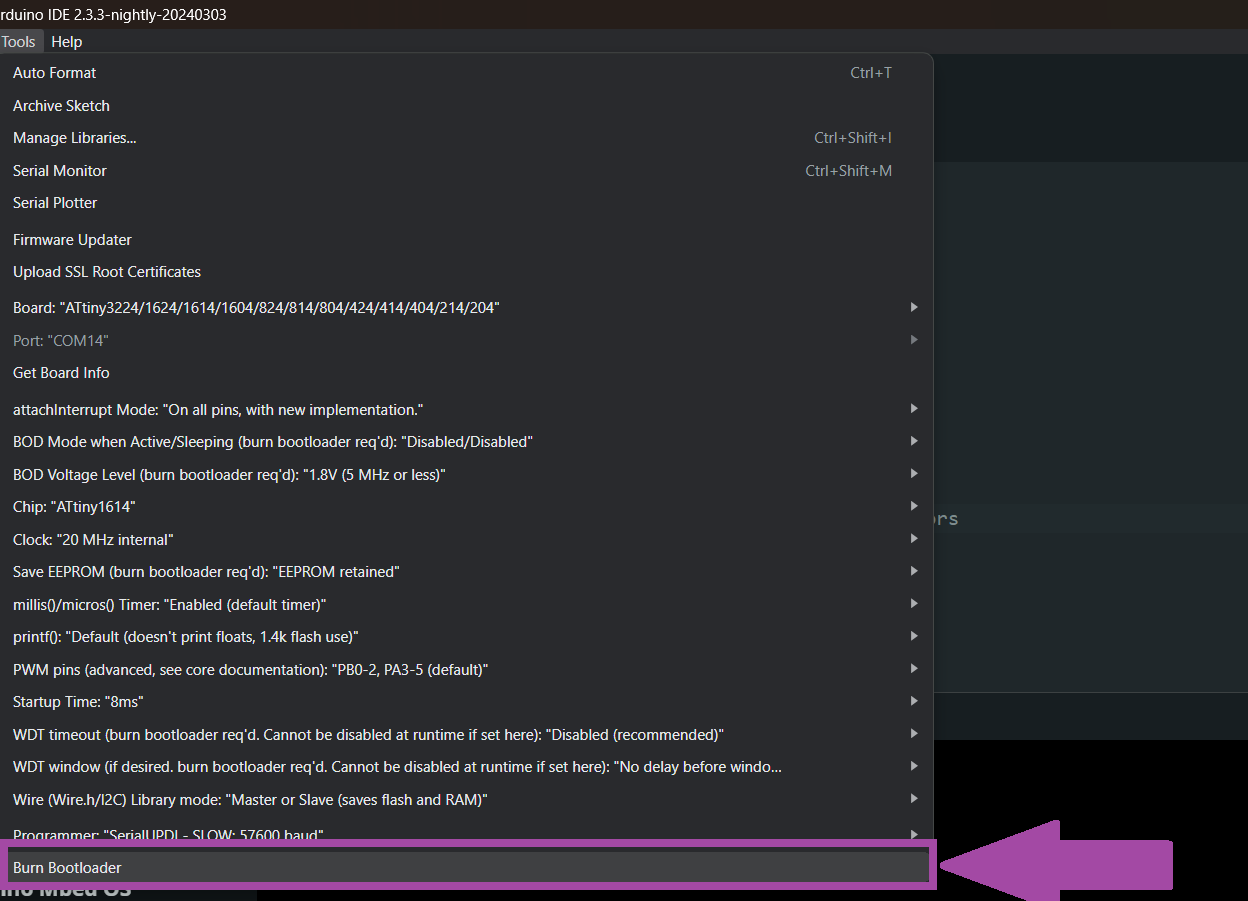
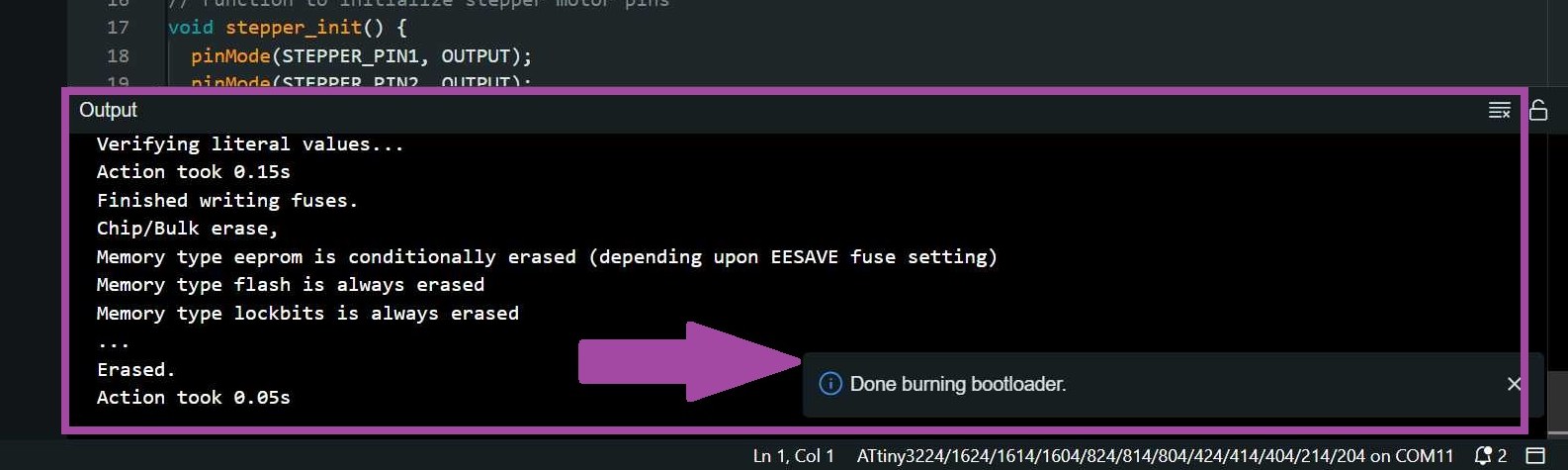
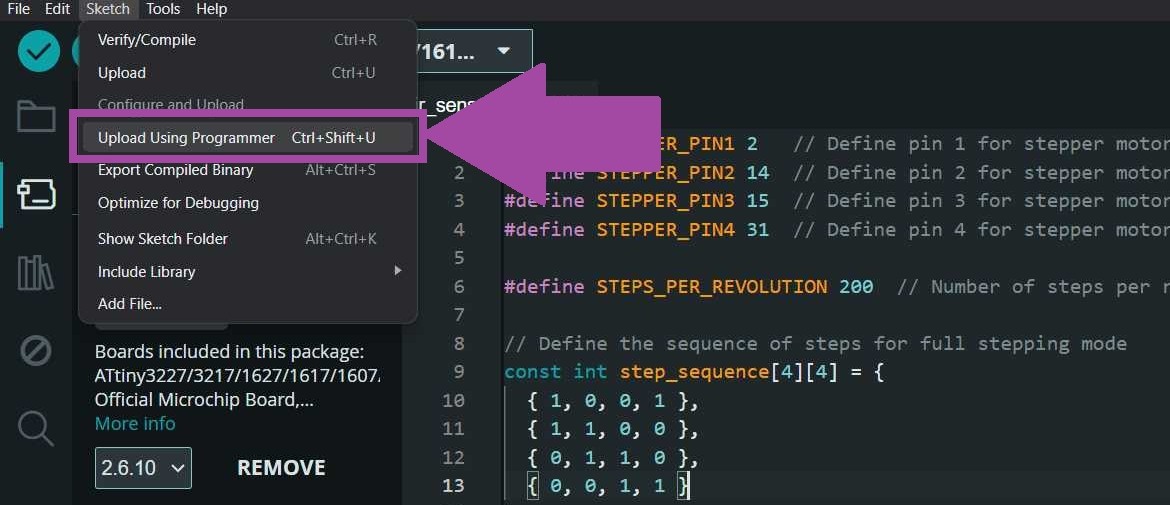
Programming the ATtiny 1614 using a programmer
Servo with New Board
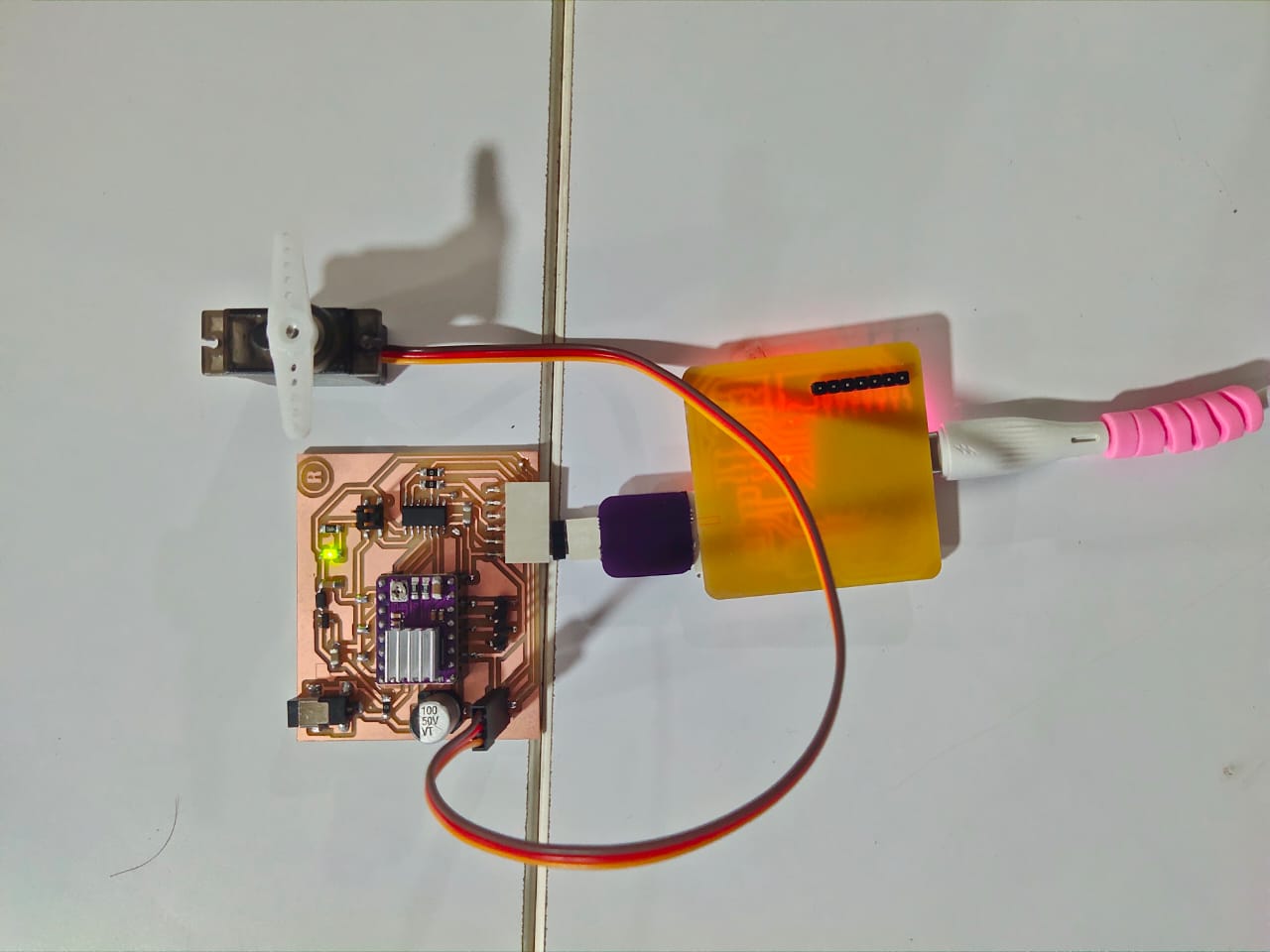
Servo Sweep Code
/* Sweep
  by BARRAGAN <http://barraganstudio.com>
  This example code is in the public domain.

  modified 8 Nov 2013
  by Scott Fitzgerald
  http://www.arduino.cc/en/Tutorial/Sweep
*/

#include <Servo.h>

Servo myservo;  // create servo object to control a servo
// twelve servo objects can be created on most boards

int pos = 0;    // variable to store the servo position

void setup() {
  myservo.attach(1);  // attaches the servo on pin 9 to the servo object
}

void loop() {
  for (pos = 0; pos <= 180; pos += 1) { // goes from 0 degrees to 180 degrees
    // in steps of 1 degree
    myservo.write(pos);              // tell servo to go to position in variable 'pos'
    delay(15);                       // waits 15ms for the servo to reach the position
  }
  for (pos = 180; pos >= 0; pos -= 1) { // goes from 180 degrees to 0 degrees
    myservo.write(pos);              // tell servo to go to position in variable 'pos'
    delay(15);                       // waits 15ms for the servo to reach the position
  }
}
NEMA 17 with New Board
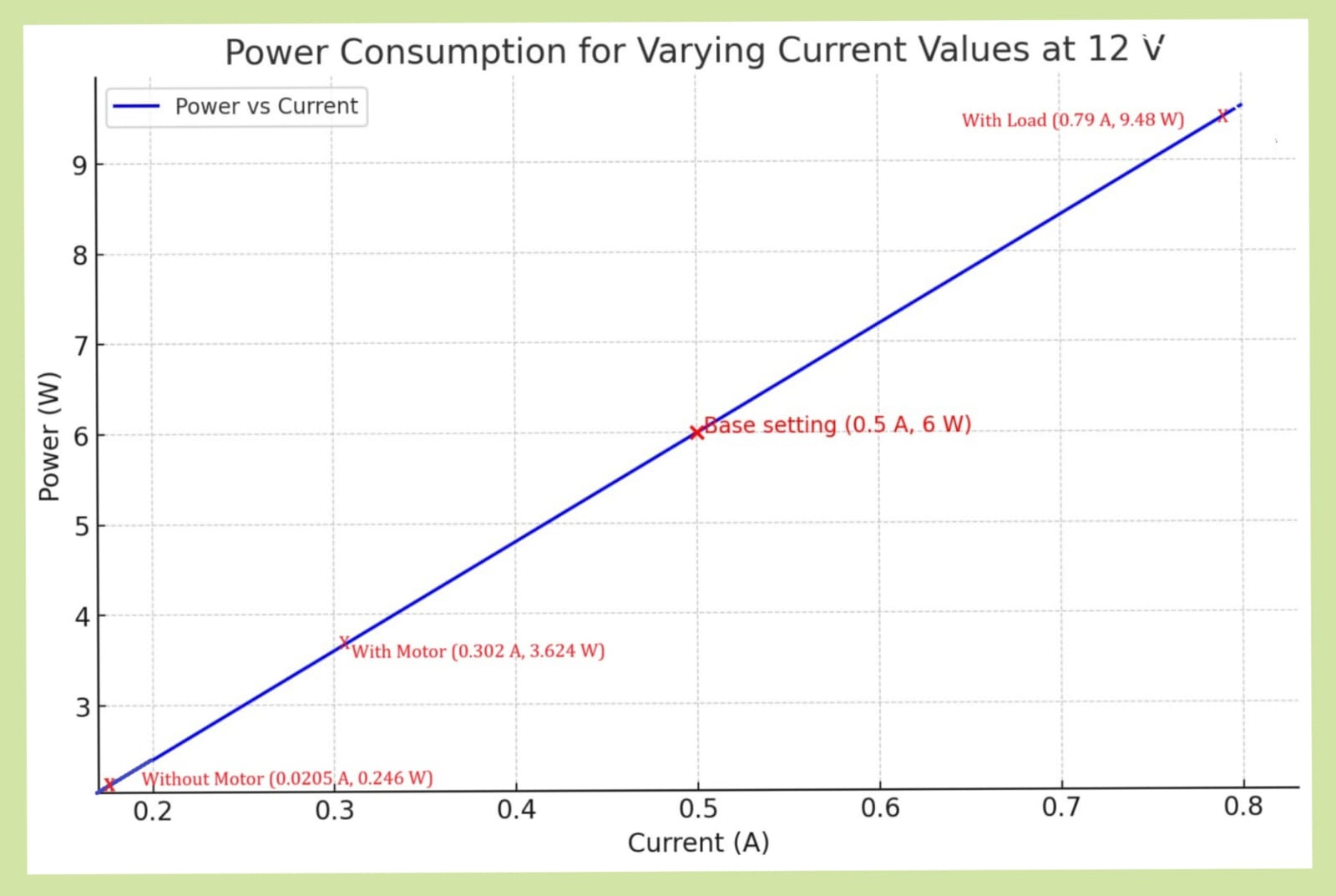
Current limit formula
Stepper motor code
const int dirPin = 0;
const int stepPin = 10;
const int faultPin = 8;
const int enablePin = 9;
const int stepsPerRevolution = 200;

void setup()
{
  // Declare pins as Outputs
  pinMode(stepPin, OUTPUT);
  pinMode(dirPin, OUTPUT);
  pinMode(faultPin, INPUT);
  digitalWrite(faultPin, HIGH);
}
void loop()
{
  // Set motor direction clockwise
  digitalWrite(dirPin, HIGH);

  // Spin motor slowly
  for(int x = 0; x < stepsPerRevolution; x++)
  {
    digitalWrite(stepPin, HIGH);
    delayMicroseconds(2000);
    digitalWrite(stepPin, LOW);
    delayMicroseconds(2000);
  }
  delay(1000); // Wait a second

  // Set motor direction counterclockwise
  digitalWrite(dirPin, LOW);

  // Spin motor quickly
  for(int x = 0; x < stepsPerRevolution; x++)
  {
    digitalWrite(stepPin, HIGH);
    delayMicroseconds(1000);
    digitalWrite(stepPin, LOW);
    delayMicroseconds(1000);
  }
  delay(1000); // Wait a second
}
Challenges and Debugging
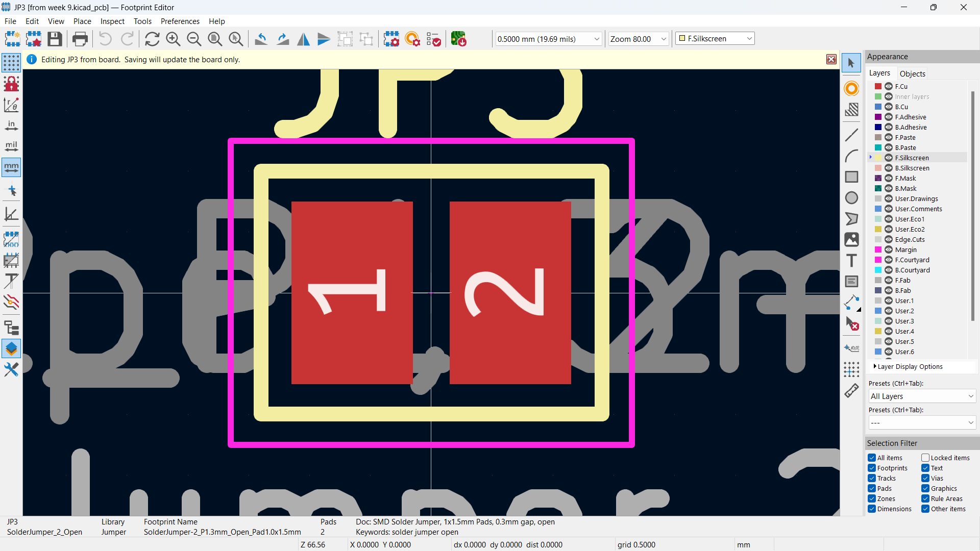
Solder Jumper Footprint Edit
The sacrificial layer is not levelled properly
Via below the horizontal socket pins
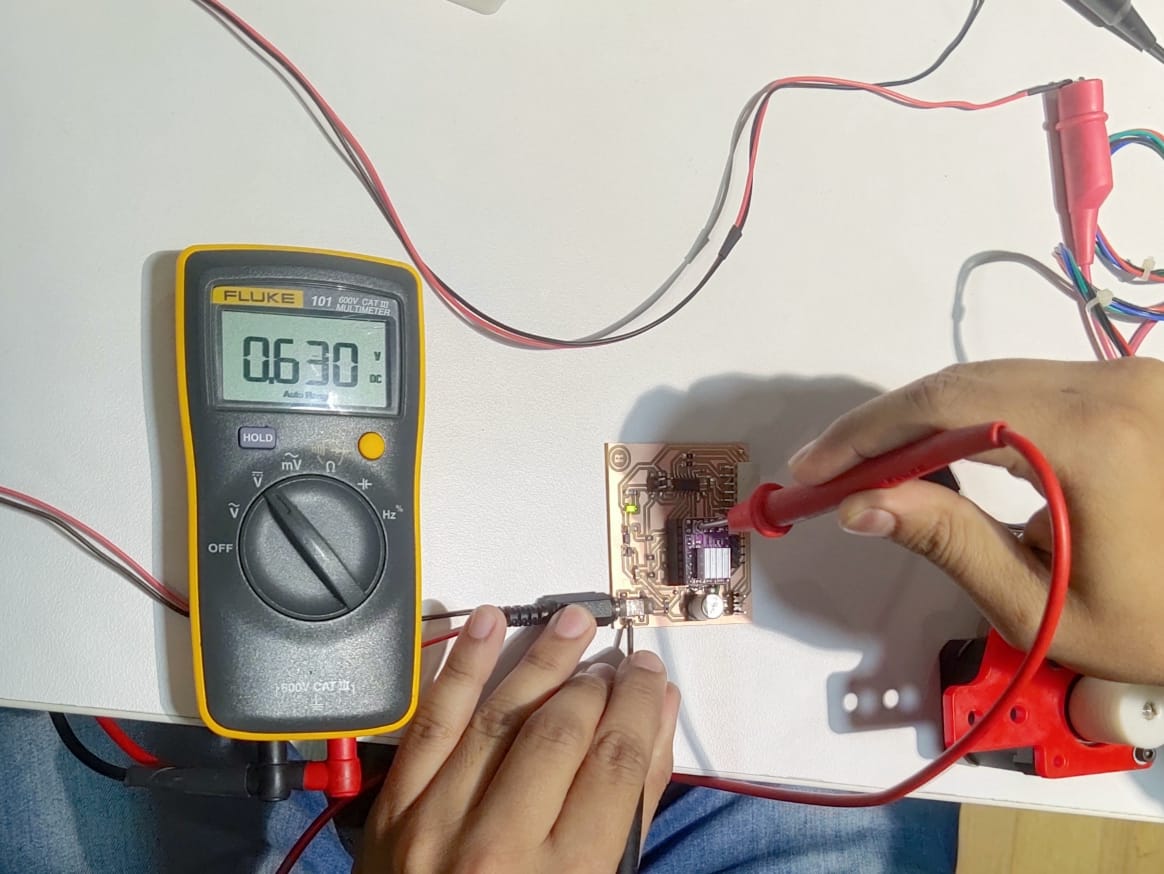
Smoking Voltage Regulator🚭🚭🚭

DRV8825 Wrong Footprint
Group Assignment Result
Reference
📌 Nadieh
Resources and Downloads