Individual Assignment
Table of Contents
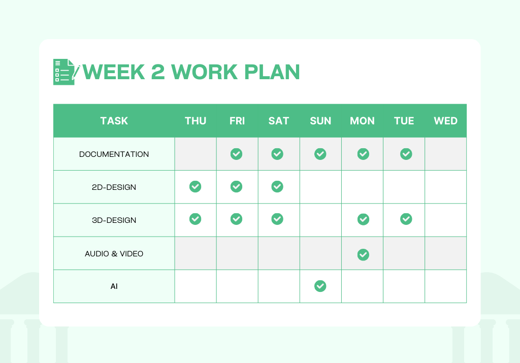
Week 2 Work Plan
2D-Design
- 2D design, also known as graphic design, is a process of creating visuals using two-dimensional elements including lines, shapes, and colour. It focuses on the aesthetic appeal and communicates a message through visual content. It's widely used in a variety of fields such as digital marketing, web design, print media and more.
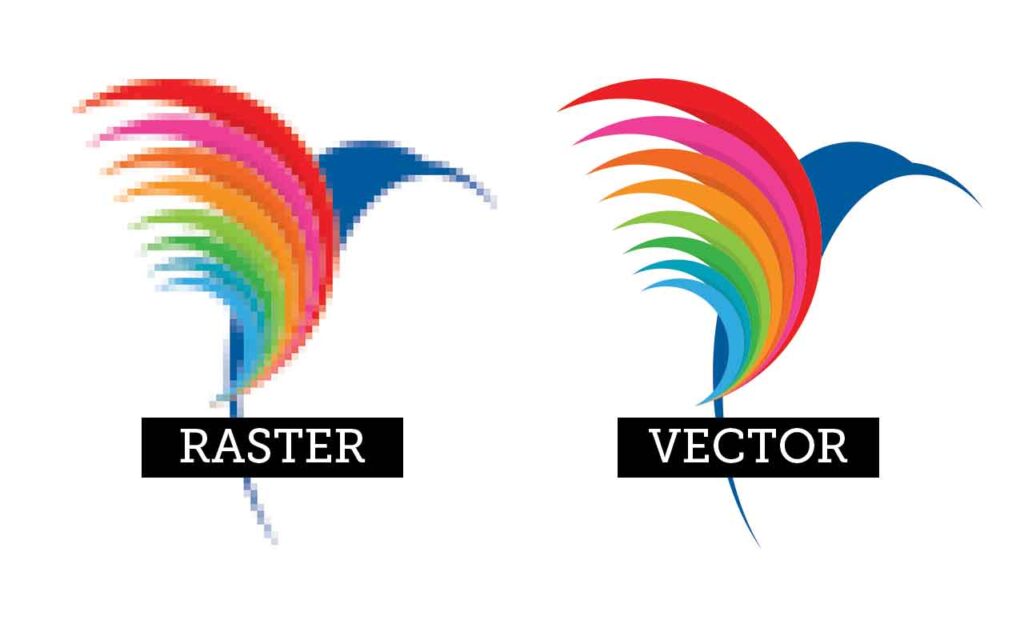
- 2D images are generally classified into two types: vector and raster.
Raster Images
- Raster images are pixel-based images that are commonly produced by digital cameras and scanners. They are made up of tiny squares of colour, called pixels, which when combined form a complete image.
- The quality of a raster image is often determined by the total number of pixels (also referred to as the image resolution), and the amount of information in each pixel (also known as color depth). Some common types of raster images include JPEG (Joint Photographic Experts Group), GIF (Graphics Interchange Format), PNG (Portable Network Graphics), RAW, BMP (Bitmap), PCX (Personal Computer eXchange), PSD (Photoshop Document) and TIFF (Tagged Image File Format).
- Raster images are ideal for detailed and complex images, such as photographs. However, one of the downsides of raster images is that they can lose quality and appear pixelated when enlarged beyond their original size.
Vector Images
- Vector images are graphics that are created using mathematical equations to define shapes and elements.
- Unlike raster or bitmap images, which are composed of pixels, vector images are resolution-independent, meaning they can be scaled infinitely without losing quality. This is because the mathematical equations that define the shapes can be recalculated for different sizes, ensuring that the image remains crisp at any scale. This makes vector graphics particularly well-suited for logos, icons, illustrations, and other designs where scalability is crucial.
- Common vector file formats include SVG (Scalable Vector Graphics), AI (Adobe Illustrator), EPS (Encapsulated PostScript), CGM (Computer Graphics Metafile), CDR (CorelDRAW) and PDF (Portable Document Format). These formats are widely supported by graphic design software and are compatible with various platforms.
Raster Tools
- There are several open-source and commercial raster tools available for use, including Pixlr, Photopea, MyPaint, Photoshop, GIMP, and Krita, but I decided to try out the tools mentioned below to create raster images.
- Use Raster Tools When: Photographic Images, Complex Textures and Effects, Realistic Artwork, Editing Pixel-by-Pixel, and Photorealistic Renderings.
- I have decided to try out some tools, and out of several options available, I have chosen the ones listed below.
- Photopea
- GIMP
- Krita
Photopea
Photopea is a web-based graphics editor, which is a great tool for editing raster and vector graphics. It supports a variety of file formats including .PSD, .AI, .XD, .PDF, among others. It has a similar interface to Adobe Photoshop, making it an accessible tool for those familiar with Adobe's software. The tool is free to use with optional ad-free subscriptions available for purchase.
 https://www.photopea.com/
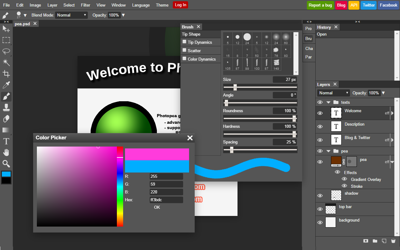
🟩To start with, I imported my passport-size photo into Photopea.

🟩Then I duplicated the layer of my photo.
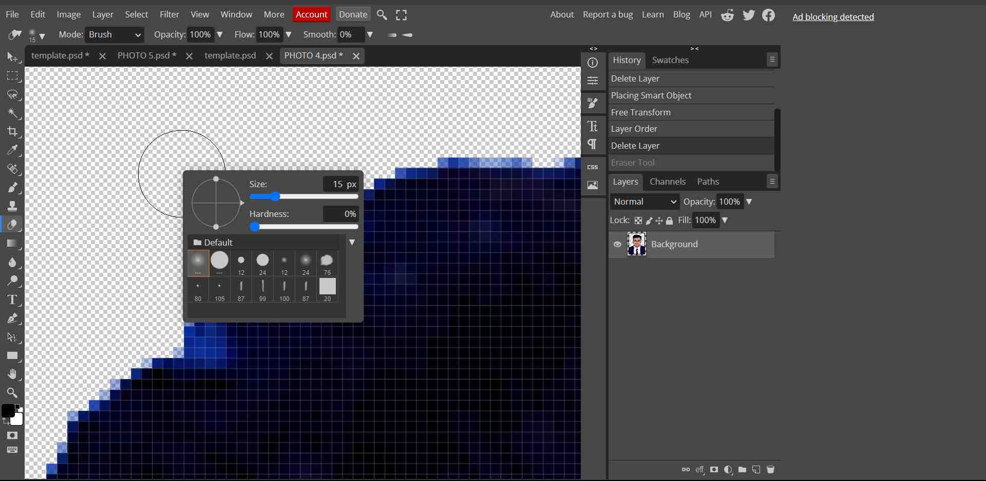
🟩In order to remove the background, I have used the “Magic Eraser” tool. It’s a magic 🪄 tool, it functions just like it sounds.

🟩 The initial background colour was not removed by the magic eraser. So, I used the “Eraser” tool and erased the background colour from my photo.
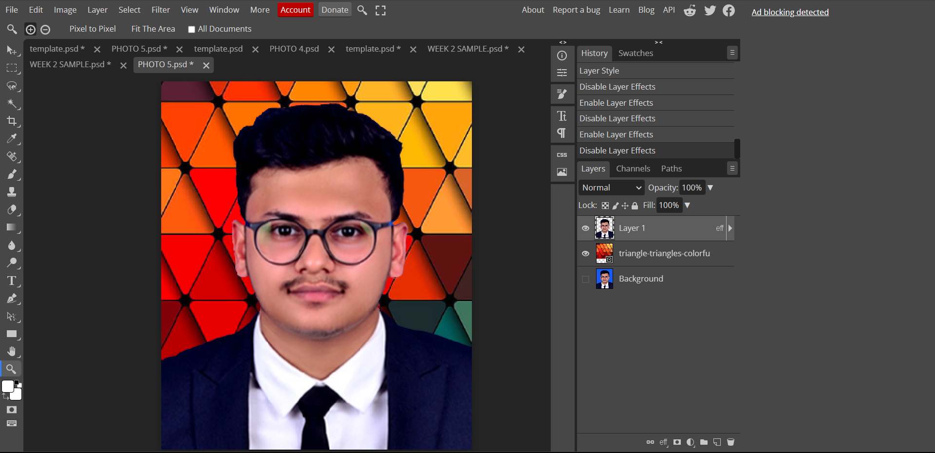
🟩 Import my desired background with the “open & place” option in the file menu.
🟩 Adjusted the layers to get my desired output.
GIMP
GIMP (GNU Image Manipulation Program) is a free and open-source raster graphics editor. It's primarily used for tasks such as photo retouching, image composition, and image authoring. GIMP supports numerous file formats and is notable for its flexibility and features, including filters and plugins.
 https://www.gimp.org/

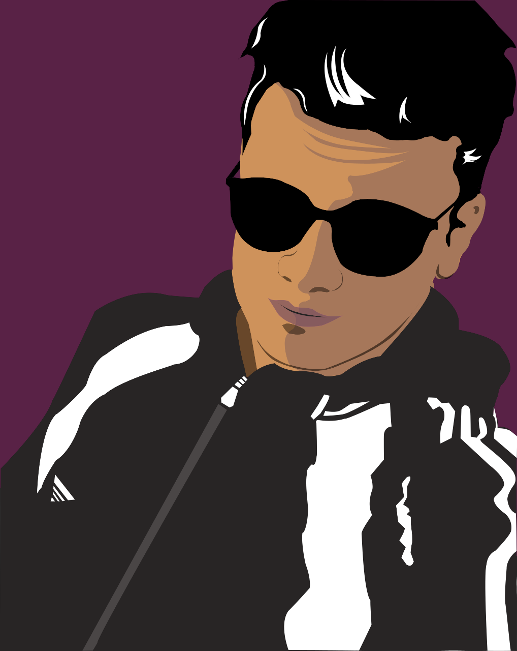
🟩To start with, I imported my photo into GIMP.
.png)
🟩Made separate layers for each part of my pic and used path tool to draw the shapes and outlines and added colours to the shapes.
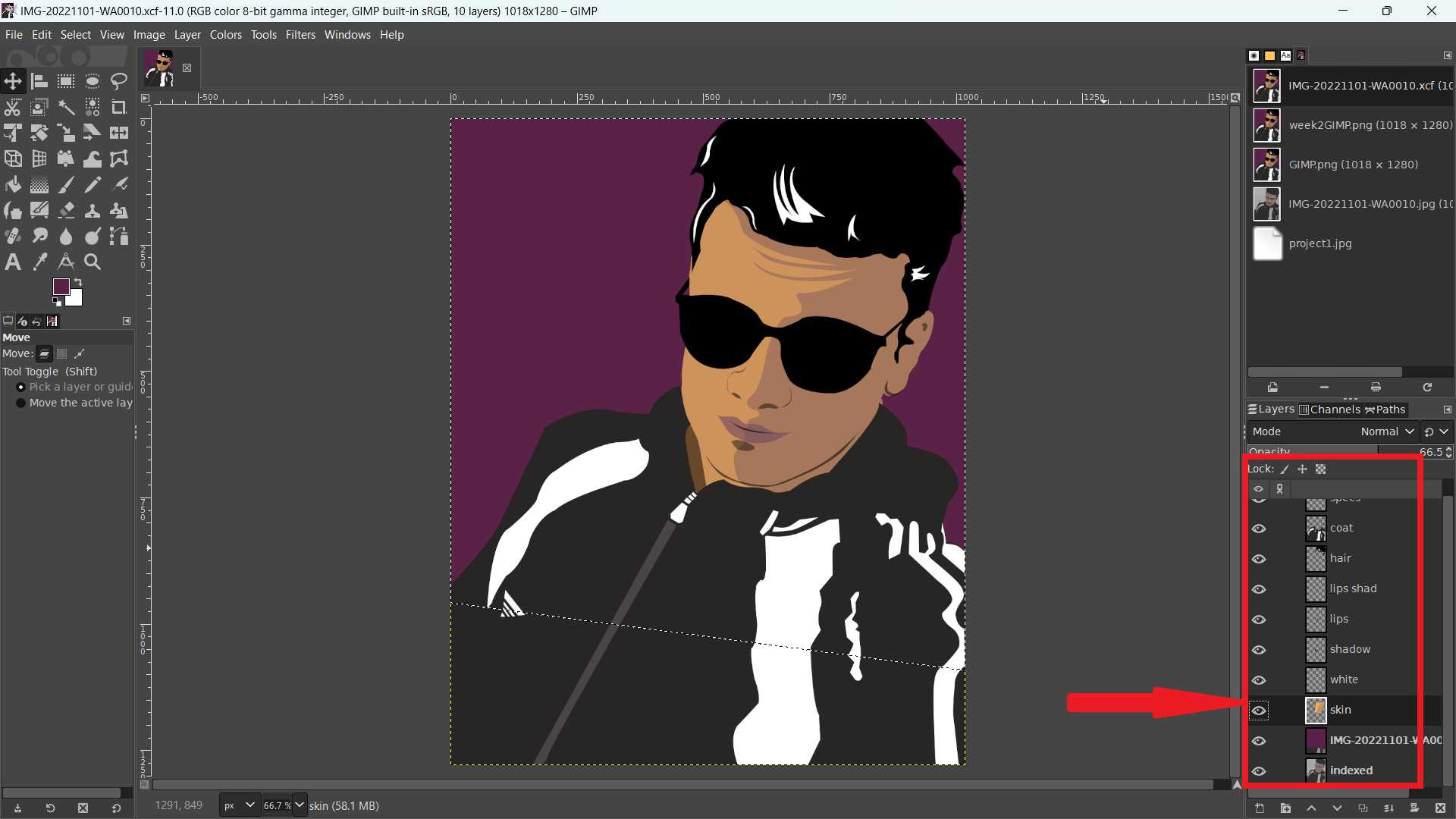
🟩 Here is the final result
Vector Tools
- There are several open-source and commercial raster tools available for use, including Potrace, Inkscape, Illustrator, Sketchpad, Scribus and so on.
- Use Vector Tools When: logos and icons, illustrations and cartoons, typography and fonts, branding and identity, infographics and diagrams, and for simple and clean designs.
- I have chosen to test the vector tools listed below from a selection of various tools.
- Inkscape
- Illustrator
Inkscape
Inkscape is a Free and open source vector graphics editor for GNU/Linux, Windows and macOS. It offers a rich set of features and is widely used for both artistic and technical illustrations such as cartoons, clip art, logos, typography, diagramming and flowcharting.
 https://inkscape.org/release/inkscape-1.3.2/
- Tracing a bitmap is the process of converting a raster image into paths that can be edited in a design. This process is also called "vectorization" or "stroke tracing".
🟩 The “Logo Maker” tool was used to generate the logo for my robotic manipulator.
🟩👉 Open Inkscape 👉 “File” menu 👉 “Open”👉 Select the Logo
.png)
🟩 From the top menu bar select 👉 “Path” 👉 “Trace bitmap” 👉 “Apply”
.png)
🟩 Changed the colour for the below colour bar.
.png)
🟩 Here is the final result

Illustrator
Adobe Illustrator is a vector-based design and drawing program. It's used to create drawings, illustrations, and artwork. Designers use it to create logos, icons, symbols, patterns, posters, and more.
🟩While looking for a design to create in Adobe Illustrator, I discovered a place near to fab lab and imagined a green octopus emerging from it. I decided to take a picture.
🟩Imported the photo into Illustrator
🟩I downloaded an image of an octopus from online and imported it into my illustrator file from: file 👉 place.
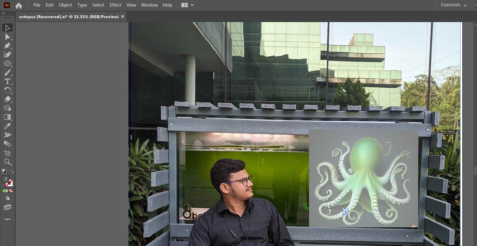
🟩Adjusted the photo and used curvature tools, shape tools and other several tools to create an octopus character.
🟩Finally, adjusted the opacity to obtain the final result.
.png)
3D-Design
3D design is a creative process that involves the creation of three-dimensional digital models or representations of objects, scenes, or structures. This field has gained significant prominence across various industries, including architecture, manufacturing, gaming, animation, and product design. 3D design allows for a more realistic and immersive representation of concepts, making it a valuable tool for visualization, prototyping, and communication.
Fusion 360
Fusion is a commercial computer-aided design, computer-aided manufacturing, computer-aided engineering and printed circuit board design software application, developed by Autodesk.
 https://www.autodesk.com/education/edu-software/overview?sorting=featured&filters=individual
- I have decided to design my project in Fusion 360.
- Open Fusion 360 and start a new design.
- Each part and link are made using separate components from the “assemble section" 👉 "component". It helps us organize the drawings and designs .
- Design the base or platform of the robotic manipulator. This may involve creating a solid body or assembly.

- Model each joint and link of the manipulator based on the defined specifications. Use sketches, extrusions, and rotations to form the basic structure.
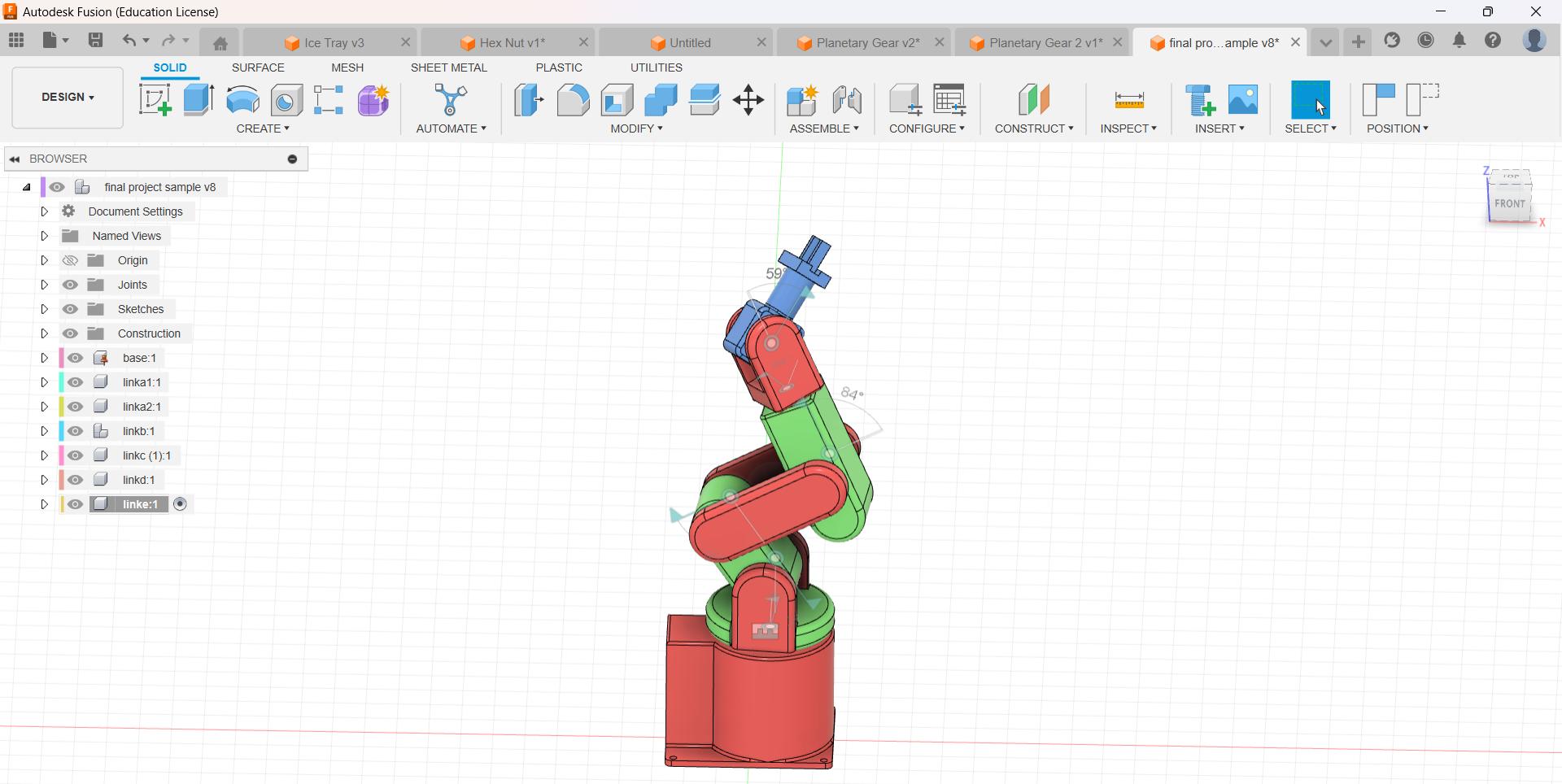
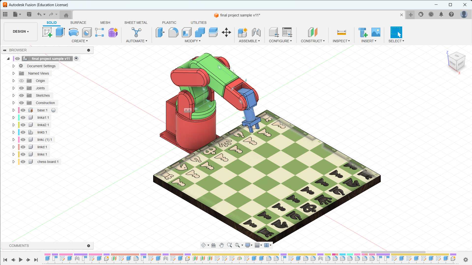
- The base of the robotic arm is grounded. Revolute joints and rigid joints are added to the links of my robotic arm.
- The image of the chess board is added from “insert menu” and “decal”. To change the material, select the “modify” menu and select “physical material".
- To change the appearance, select the “modify” menu and select “Appearance” or press "A".
- Changed the view from “single view” to “multiple view”

- The workspace is changed from “Design” to "Render”, and select "In-Canvas Render” to render the CAD model.

Animation in Fusion 360
Onshape
Onshape is a cloud-based computer-aided design (CAD) software platform. It allows users to create, edit, and collaborate on 3D designs in real-time through a web browser. Onshape is known for its collaborative features, which enable multiple users to work on the same design simultaneously, making it a popular choice for distributed teams and collaborative design projects.
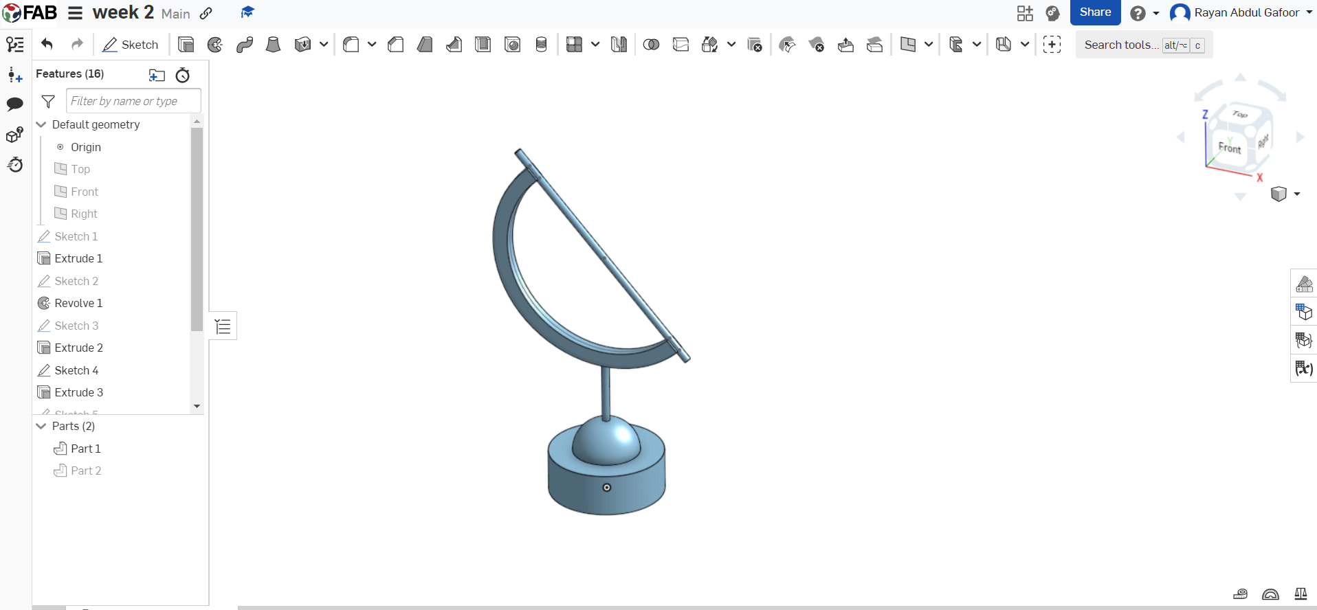
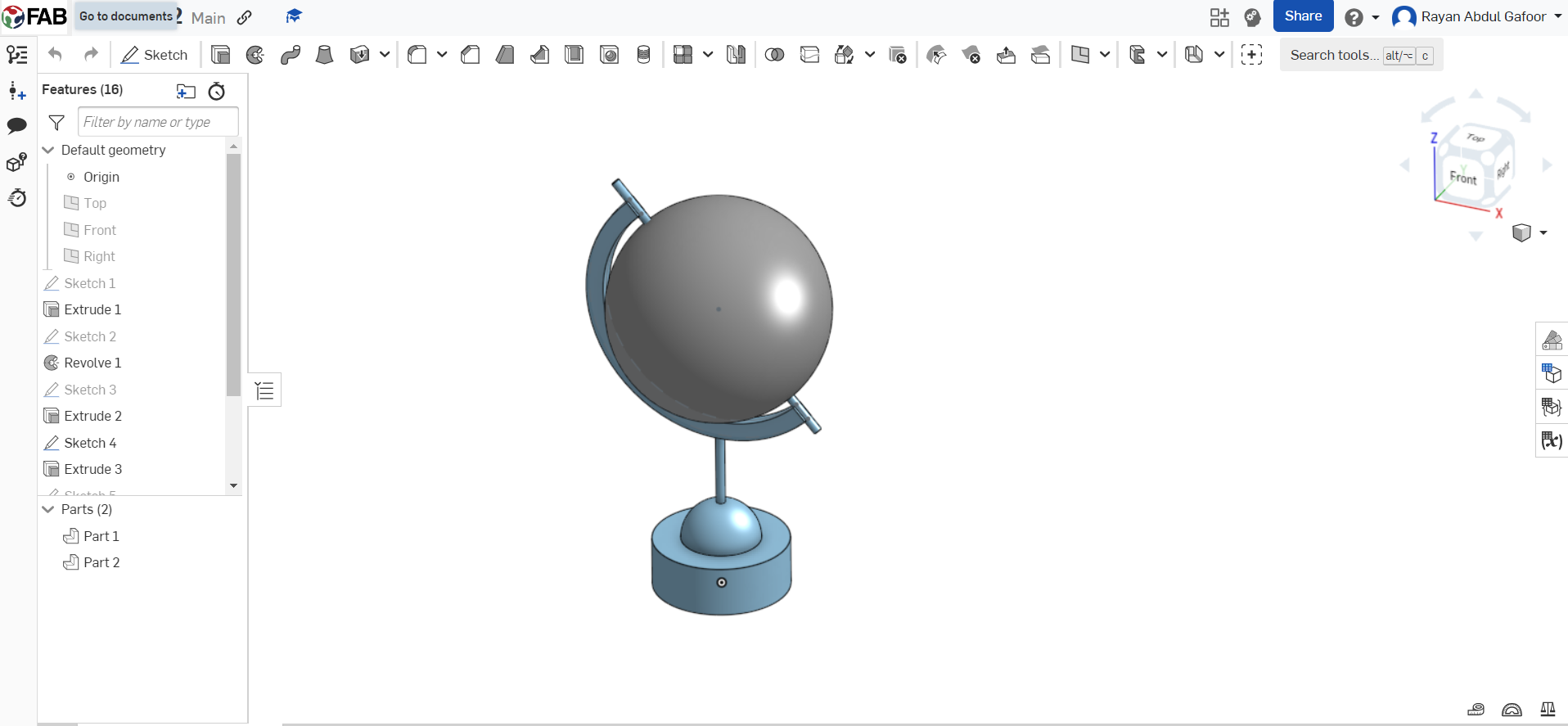
- Start a new sketch on the XY plane.
- Use the circle tool to draw a circle, which will represent the equator of the globe. Set the circle's diameter based on my desired globe size.
- Exit the sketch and use the extrude tool to give the circle volume. Enter the desired thickness for your globe.
- Create a new sketch on the surface of the extruded circle. used the circle to draw the circle and then revolve it.
- Use circle tools to draw a circle represent the stand bar of the globe, and extrude it.
- Use the circle tool and trim tool to draw a semi-circle and extrude it.
- Save the Onshape document.
SolidWorks
SolidWorks is a powerful and widely-used computer-aided design (CAD) software developed by Dassault Systèms. It is known for its robust 3D modeling capabilities and is extensively used in various industries for product design, engineering, and manufacturing.
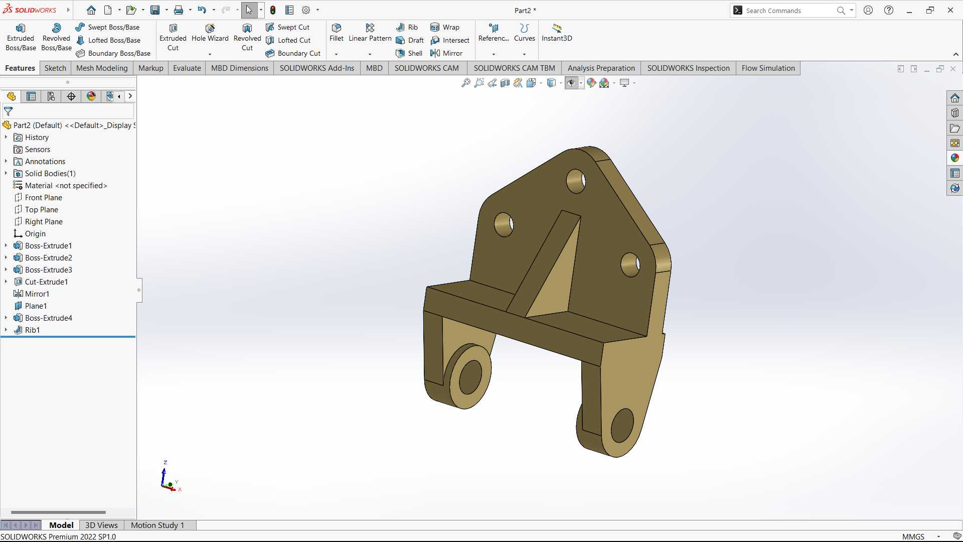
- Launch SolidWorks and create a new part document.
- Start a 2D sketch on the plane to create the bracket.
- Use sketch tools such as lines, rectangles, circles, or arcs to outline the basic shape of your bracket.
- Apply dimensions and constraints to define the size and relationships between sketch entities. This ensures that your bracket has the desired dimensions and maintains proper proportions.
- Exit the sketch and use the Extrude feature to give your 2D sketch volume in the third dimension. Specify the extrusion distance to determine the thickness of your bracket.
- Depending on design requirements, add more features such as holes, fillets, chamfers, or cuts. Use features like Extrude Cut, Fillet, and Chamfer to modify the bracket as needed.
- Assign a material to the bracket.
- Save the SolidWorks part document, and if necessary, export the 3D model in a format suitable for your needs, such as STL or STEP.
Blender
Blender is a free and open-source 3D computer graphics software tool set used for creating animated films, visual effects, art, 3D-printed models, motion graphics, interactive 3D applications, virtual reality, and, formerly, video games.
 https://www.blender.org/download/
- Initially, from the cube position, Press “S” to scale, and press “Y” to lock in the y axis.
%201.png)
- Changed from “object mode” to “edit mode”.
%201.png)
- Select “edge mode” to select the edges and move along the z-axis.

- I used the extrude option to extrude different faces and the “loop cut” option to cut the part into two sections.
- Finally, from the “object mode", I created the circle for the wheels and moved to the “edit mode” to extrude, scale, and inset the faces of the wheels.

- The overall workflow’s video is given below.
Simulation
Simulation refers to the imitation or representation of a real-world process, system, or event in order to understand, analyze, or predict its behaviour. It involves creating a model that represents the essential aspects of the system under consideration and then using that model to simulate or mimic the system's dynamics over time.
- Finite Element Analysis (FEA): FEA is a numerical technique used to analyze and simulate the behaviour of complex structures and systems. It is particularly prevalent in engineering and physics to study the effects of various forces, heat, and other physical phenomena on materials and structures. The method involves dividing a complex structure into smaller, simpler elements, and then analyzing each element's behaviour to understand the overall behaviour of the entire system.
- Static structural analysis: Static structural analysis is a type of Finite Element Analysis (FEA) that focuses on studying the behaviour of a structure or component under applied loads without considering the effects of time or dynamic forces.
SolidWorks Simulation
SolidWorks Simulation is a software tool integrated into the SolidWorks 3D CAD (Computer-Aided Design) software suite. It is a finite element analysis (FEA) solution that allows engineers and designers to simulate and analyze the structural, thermal, and fluid flow behavior of their designs directly within the SolidWorks environment.
- Performing a static structural analysis of a bracket in SolidWorks involves several steps.
- Open SolidWorks and create a 3D model of the bracket using the SolidWorks CAD tools. I have used my bracket which was already designed in SolidWorks.
- Ensure that the model is fully defined and includes all necessary details such as material properties, dimensions, and geometric features.
- Once the 3D model is complete, switch to the SolidWorks Simulation environment by selecting the "Simulation" tab from the SolidWorks Add-ins.
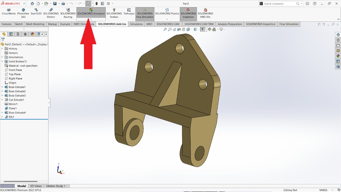
- Define the material properties of the bracket. Right-click on the "Materials" folder in the Simulation tree and assign the appropriate material to the bracket.

- In the Simulation tab, click on the "New Study" button to create a new study. Choose "Static" as the analysis type for a static structural analysis.
- Apply external loads and boundary conditions of the bracket.
- Generate a mesh for the 3D model. Meshing divides the model into smaller elements for analysis. Click on the "Mesh" icon and choose appropriate mesh settings, such as element size and type.
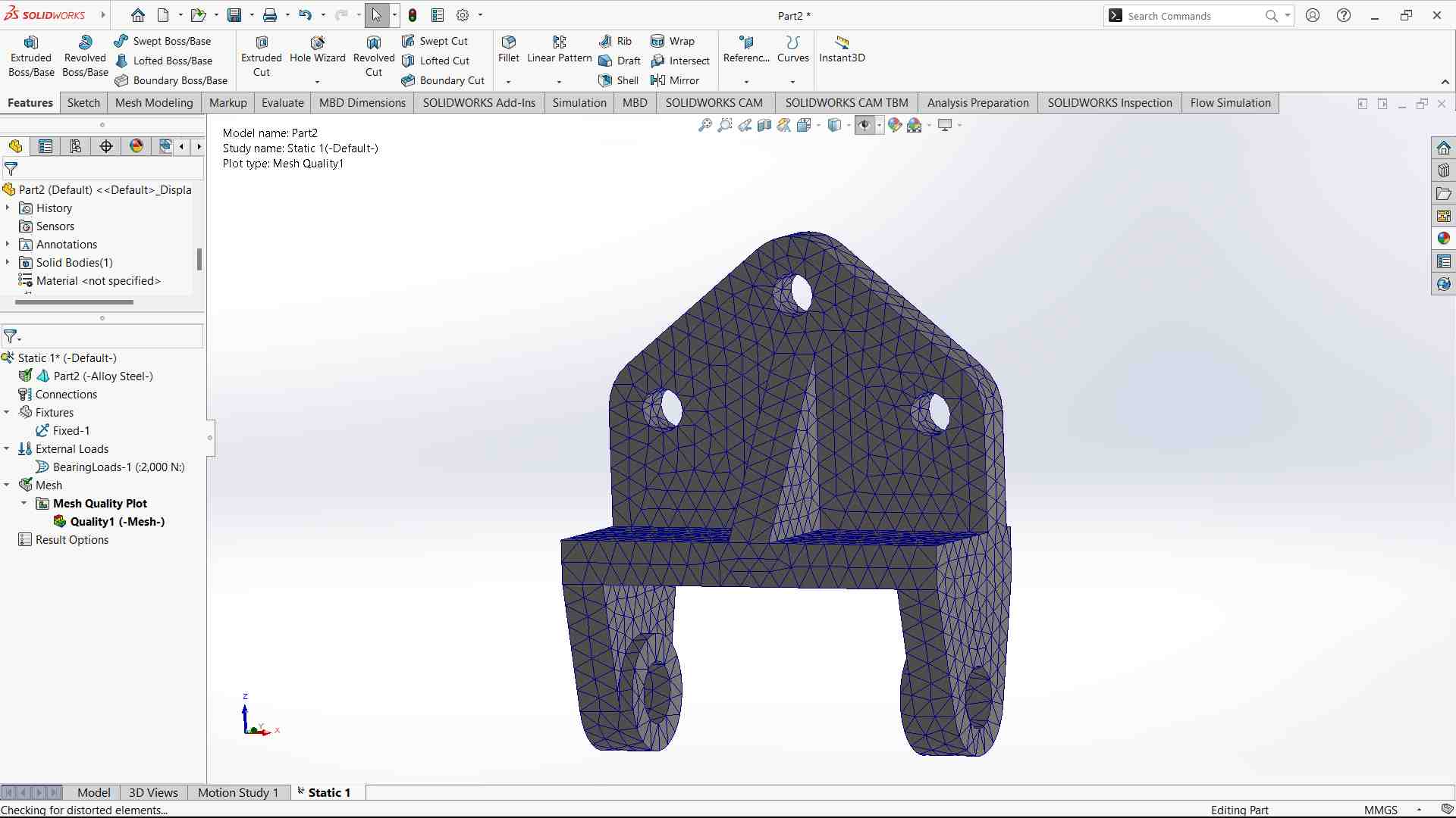
- Click on the "Run" button to start the analysis. SolidWorks Simulation will solve the mathematical equations to determine the stress, displacement, and other relevant results.
- Once the analysis is complete, review the results using the various post-processing tools available
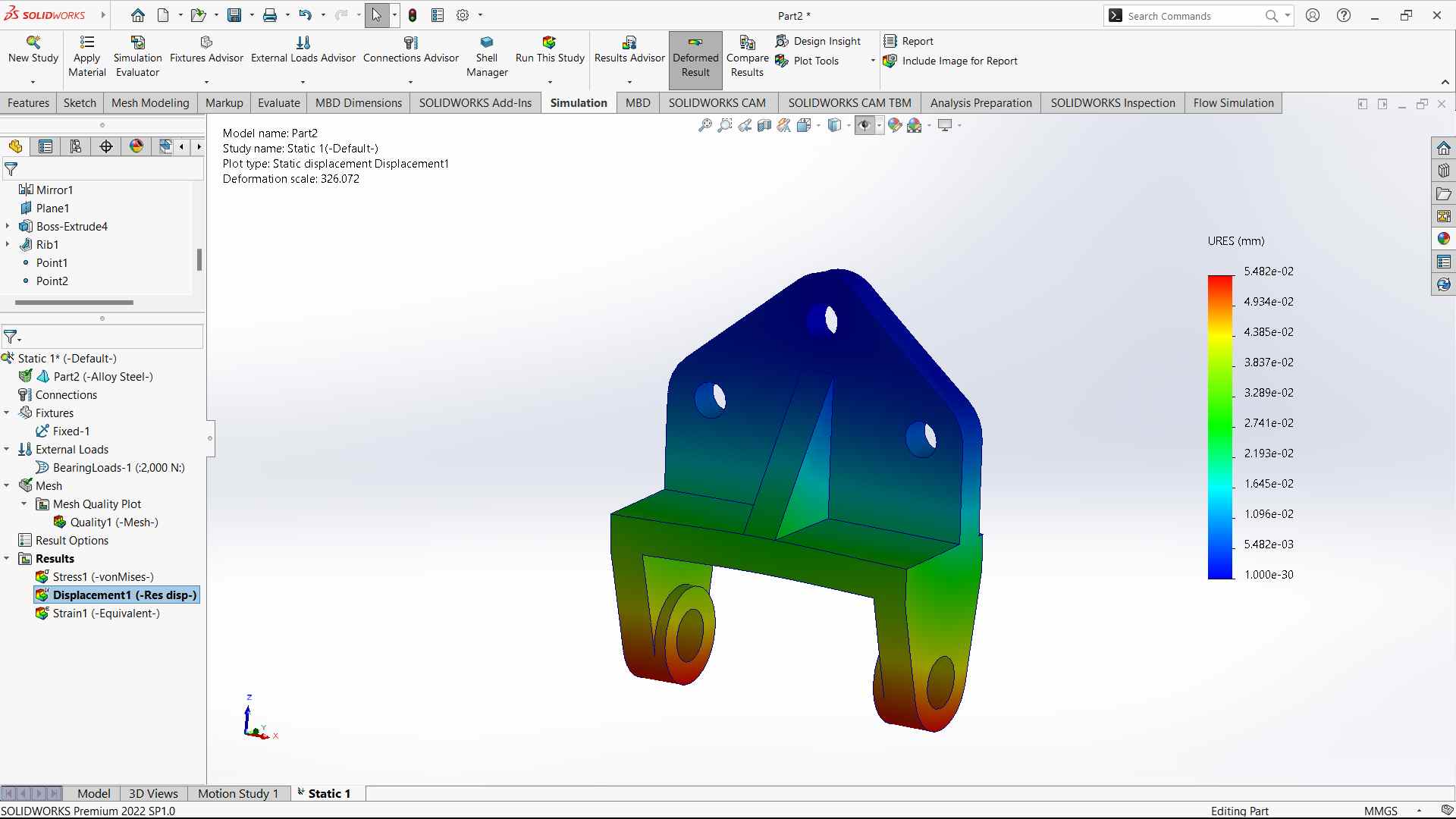
- Here is the result of the displacement of the bracket when the static load is applied.
Video Editing Software
Kdenlive
Kdenlive is a free and open-source video editing software based on the MLT Framework, KDE and Qt.
- I have used Kdenlive to edit my robotic arm animation video.
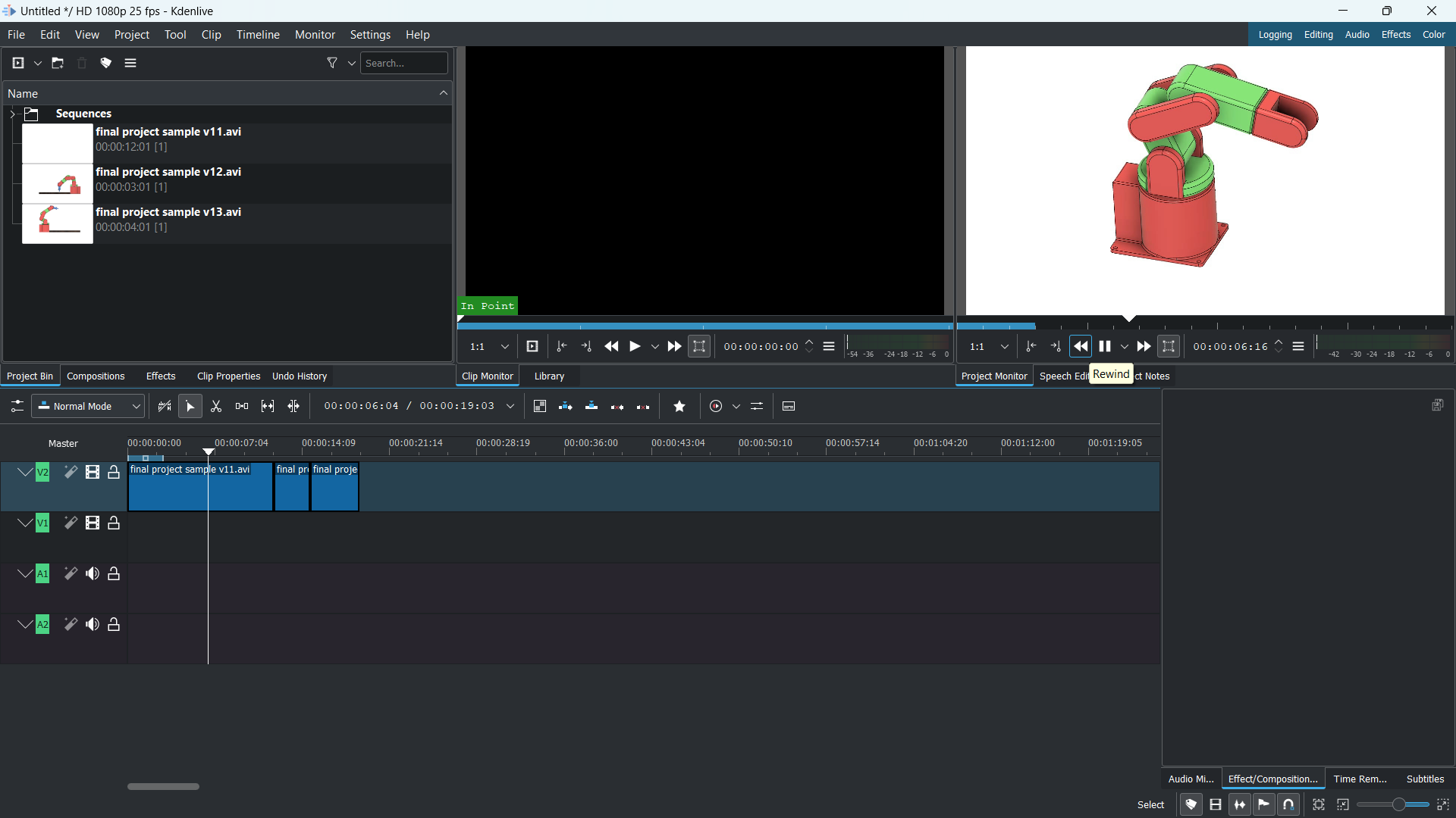
- Drag and drop the videos to edit in kdenlive.
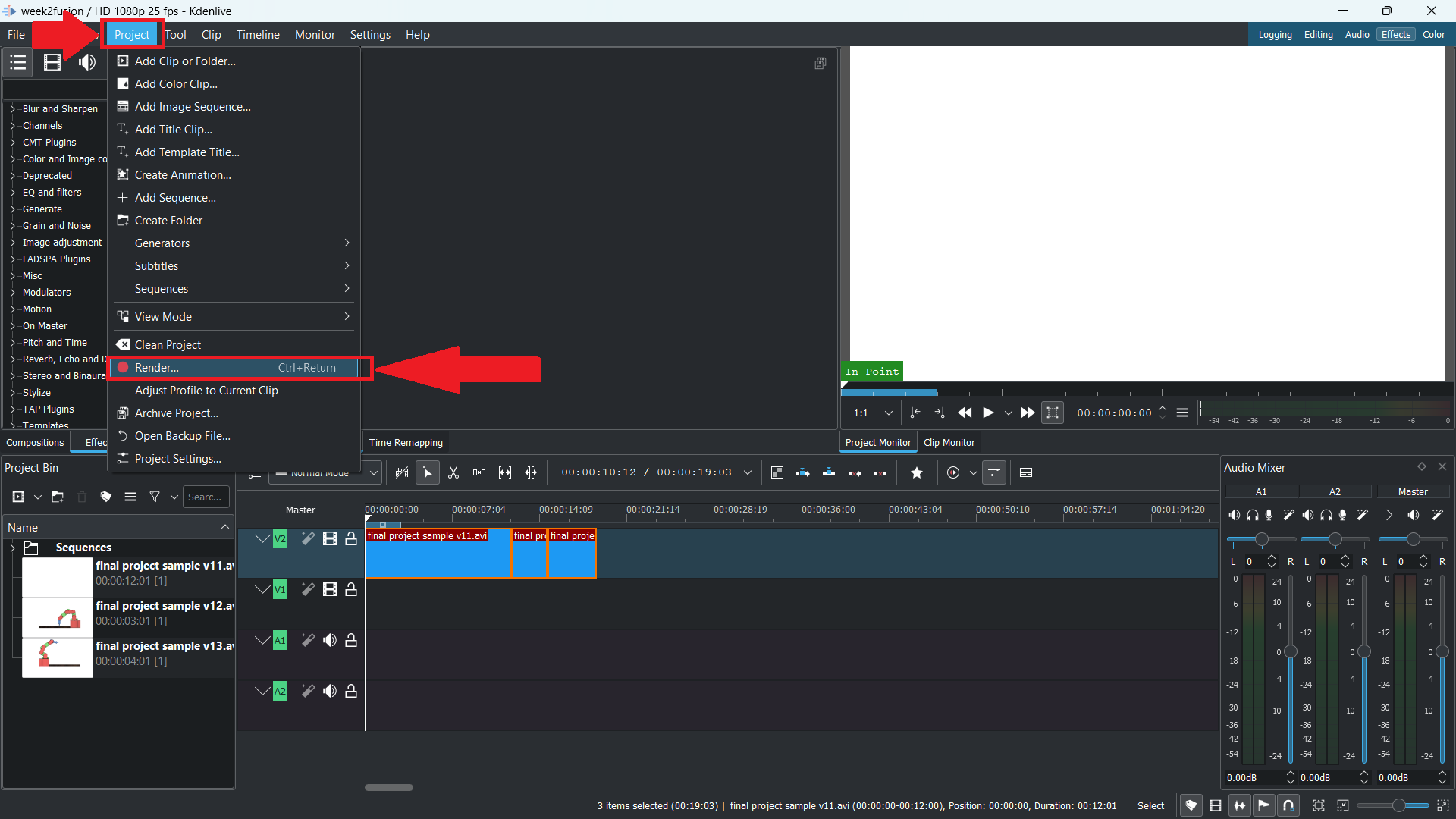
- Once done with editing the video, select the “render” option from the “project” tab or press “ctrl + return” from the keyboard.
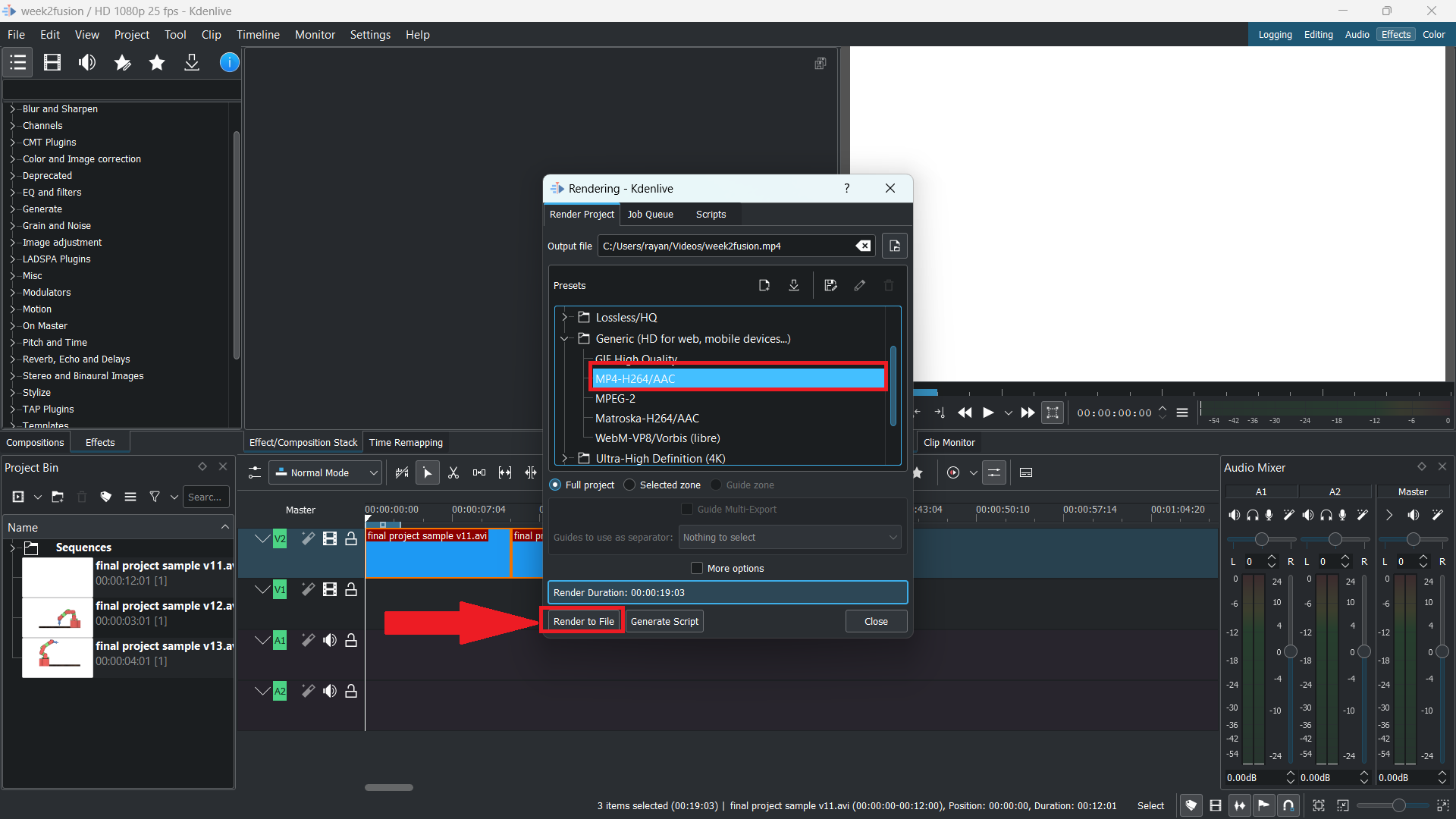
- Choose the desired output folder, and from the Generic list select “MP4-H264/AAC”.
- Choose the “Render to file” option.
Videos Compression
HandBrake
- I have utilized a tool named "HandBrake" to compress my videos.
- HandBrake is a free and open-source transcoder for digital video files.
Steps to follow
HandBrake makes it easy to compress videos.
👉 To begin, drag or click the video from the folder into the software.
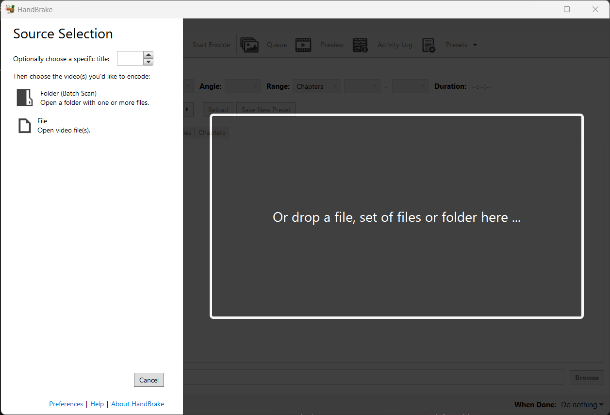
👉Go to the summary tab and check the box next to "web optimised".
👉You can change the FPS to "same as source".
👉 Choose "constant framerate" from the video tab.
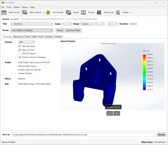
👉 Finally, click on “Start Encode”.
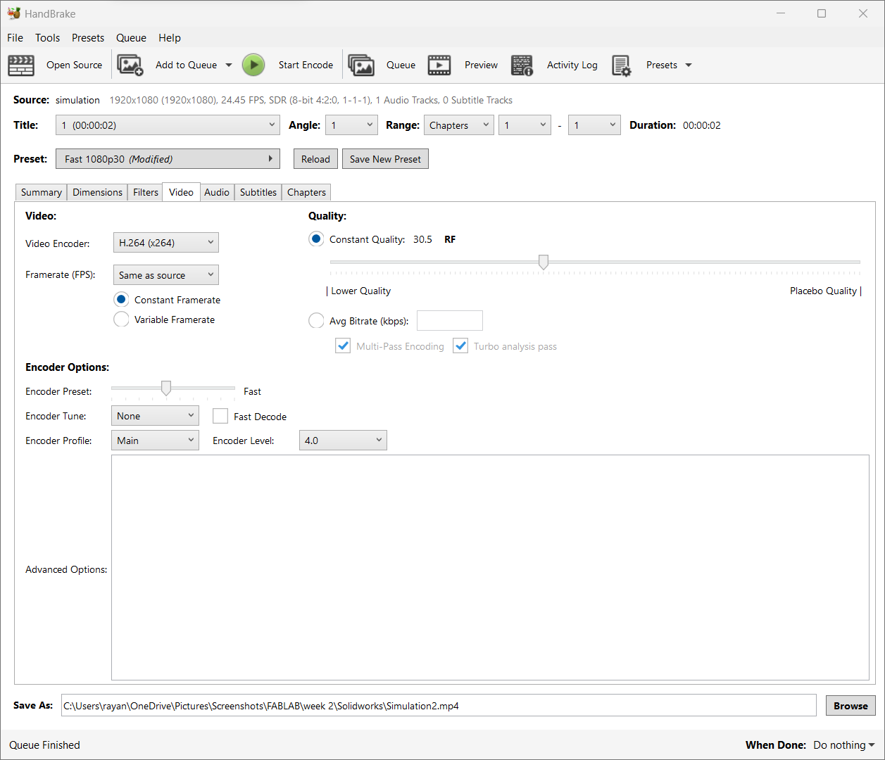
Image Compression
Zee Convert
Free online image reducer tool that will help you to reduce image size in KB without losing the image quality. Optimize it to get the accurate size in Kb's.
 https://zeeconvert.com/compress-jpg/reduce-image-size-in-kb.php
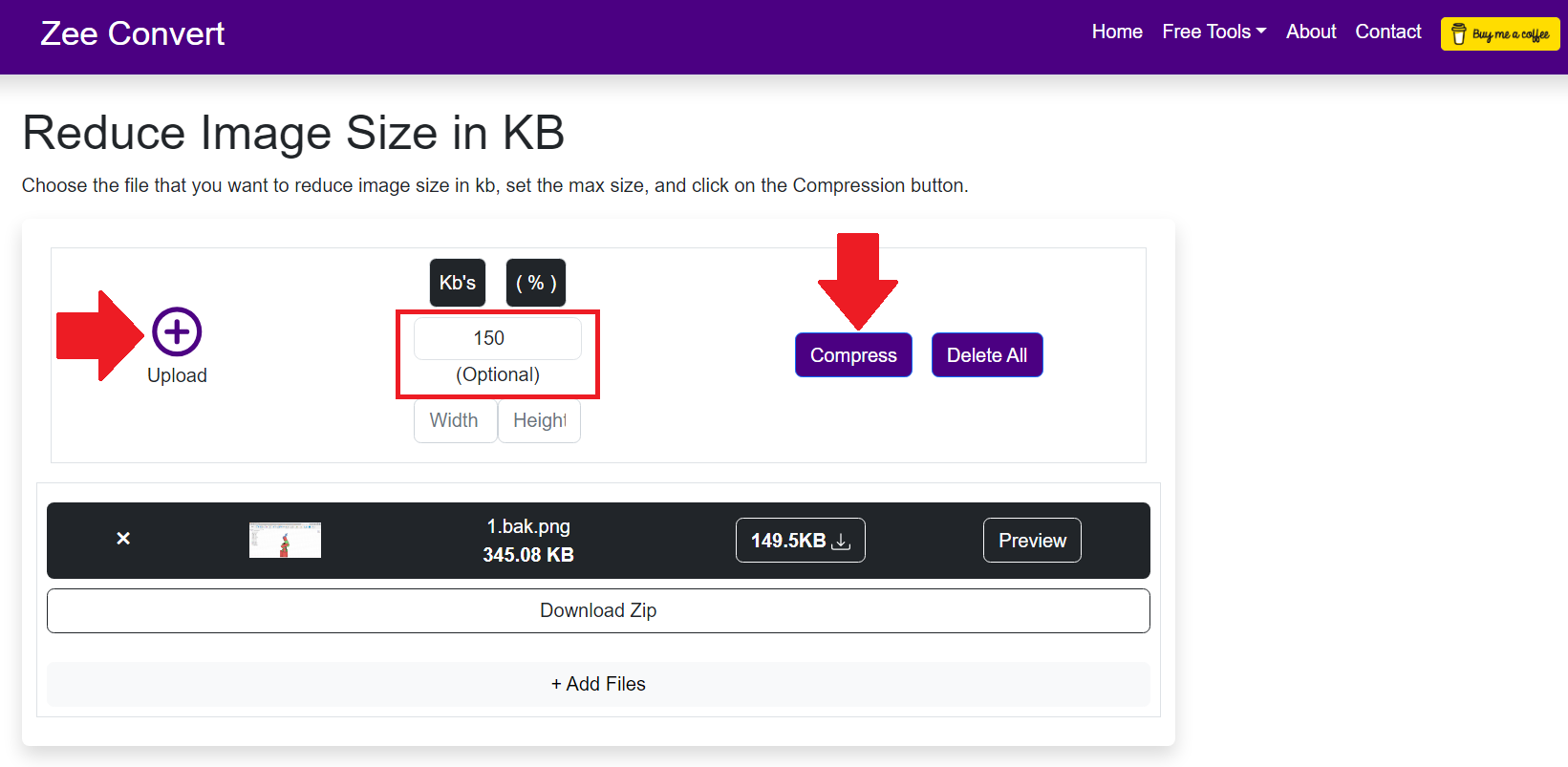
- Select the image file that you want to reduce the size in kb, Select multiple files and reduce it at once to save your time.

- Set the max size in KB. By default, it is set to 300KB or 400KB. You can also change it.
- Click on the compress button to start reducing the image size in kb.
PowerToys
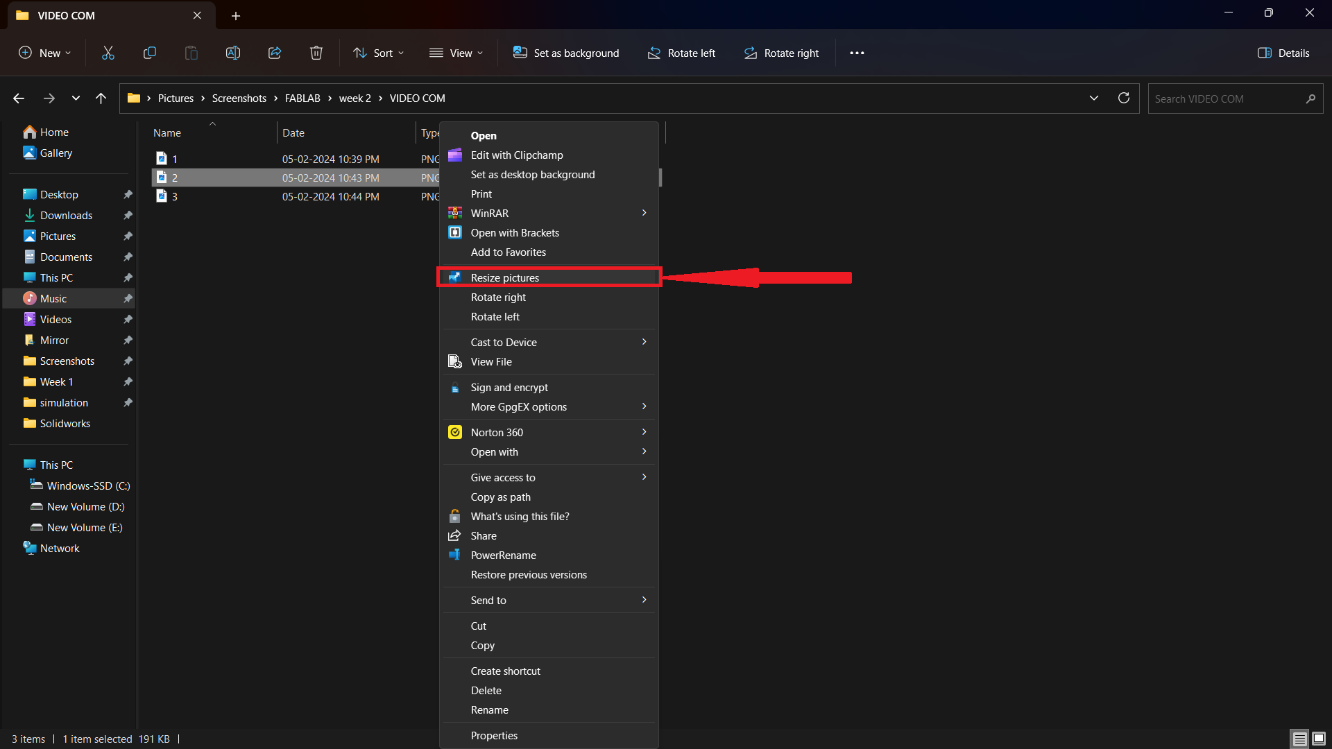
- I used Microsoft PowerToys to reduce the size of the images. One of my peers told me about this tool.
- Microsoft PowerToys is a set of freeware system utilities designed for power users, developed by Microsoft for use on the Windows operating system. These programmes add or change features to maximise productivity or add more customisation".

Steps to follow
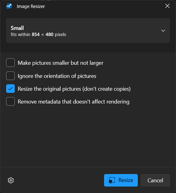
To reduce the size of images,
👉 First, right-click on the pictures you want to shrink and choose "resize picture".
👉 Last, check the box next to "Resize the original pictures" and click "resize”.
AI
AI can generate images from prompts, which typically involves the use of generative models, particularly those based on deep learning techniques. One popular class of generative models for image generation is generative adversarial networks (GANs).
- A number of AI platforms can make images based on prompts. Here are some well-known platforms:
- DALL-E
- MIDJOURNEY
- RUNWAYML
- DEEPDREAM
MIDJOURNEY
Midjourney is an AI-based image generation tool that uses a text-to-image model. In simpler terms, it can read your text prompt and create an image based on it.
- I asked Midjourney AI to draw a picture of a soft, robotic fish from the future that would be used to explore the ocean with real fish.
- I have used the prompt: Could you please keep in mind the following phrase: "An illustration of a futuristic, robotic arm for playing chess”.

- I have used the prompt: Could you please keep in mind the following phrase: "An illustration of a futuristic, soft, robotic fish for underwater exploration alongside real fish”.


