Individual Assignment
✅
Complete your final project tracking your progress.
✅
What tasks have been completed?
✅
What tasks remain?
✅
What has Worked? what hasn’t?
✅
What questions need to be resolved?
✅
What will happen when?
✅
What have you learned?
Table of Contents
About this week
✅
During this week, I was not able to be at the lab and perform this week's tasks. I was suffering from dengue fever. I could not attend or even do anything pertaining to my final project. My body was completely weak. With proper medication and rest, I was able to recover my body to some extent from its impact. Then I almost lost 10 valuable days for my final project. This project was one of the project ideas. I kept this as my backup project. Initially, I intended to do a smart chessboard. But, due to the unexpected leave, I changed my mind because I had completed the CNC milling of the rocking chair in the previous week. So I decided to pursue my backup plan. However, the rest of the tasks were started only on May 27, 2024. The time pressure was intense. So at this time of the week, I only completed the CNC milling. and I assumed a midpoint of the final work progress as this week and documented it.
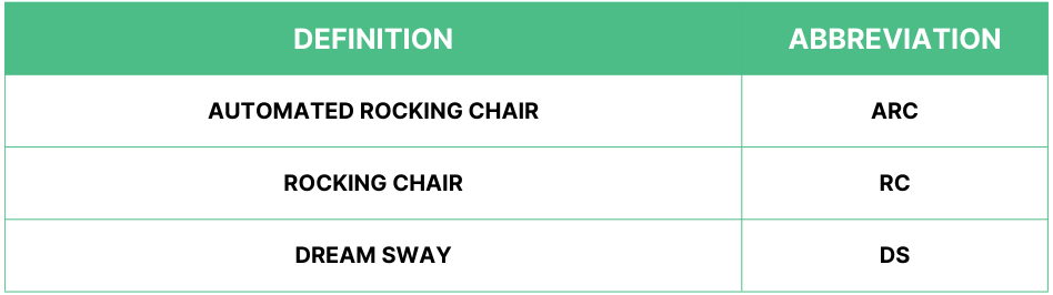
Abbreviation
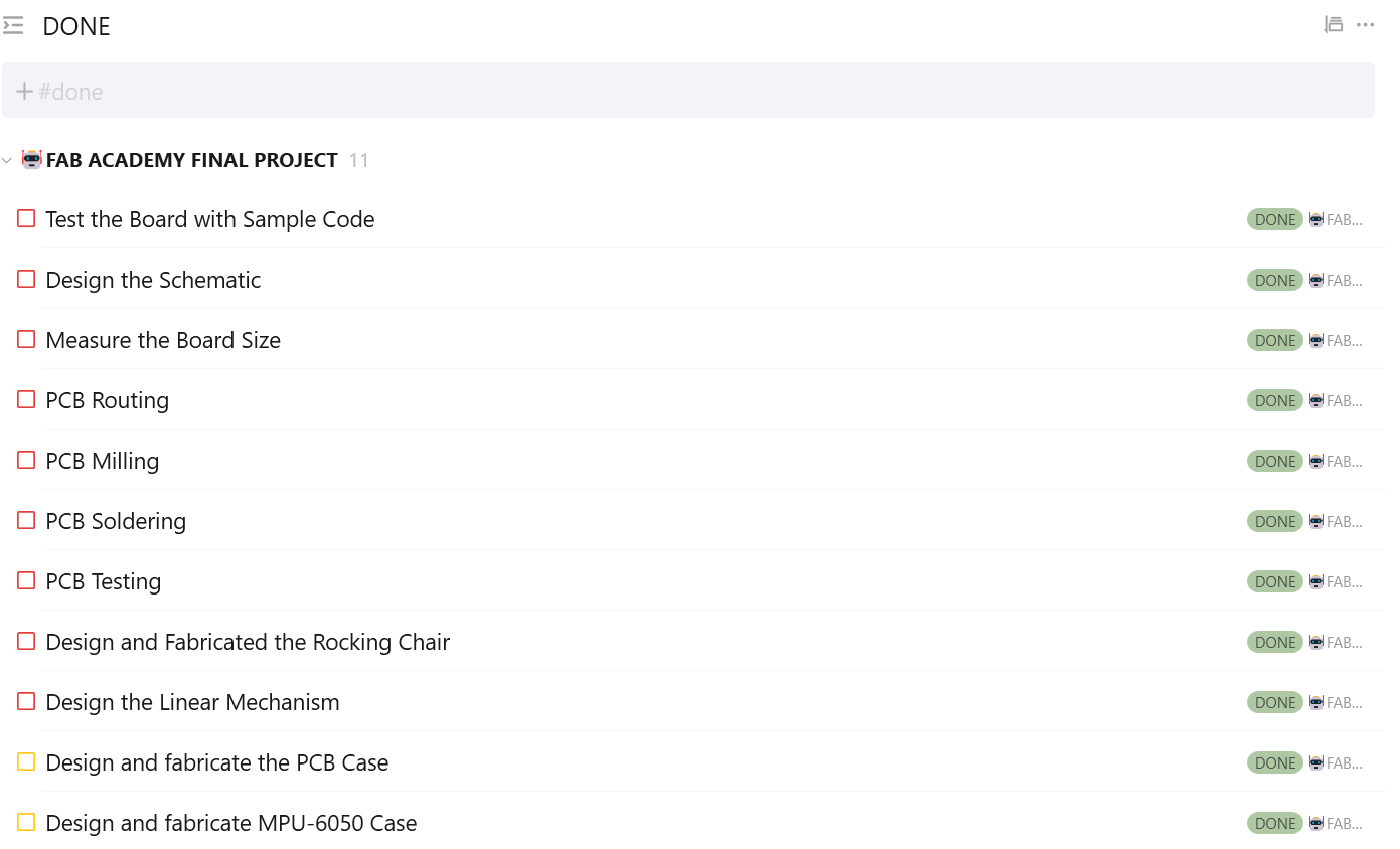
What tasks have been completed?
✅
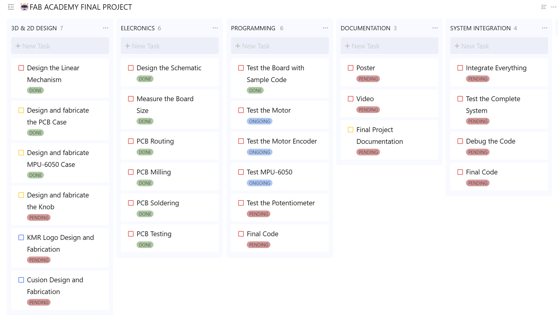
The image below illustrates the tasks that are completed.
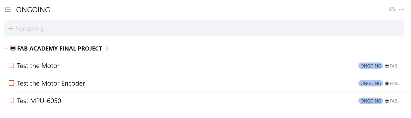
What tasks remain?
🚵🏻♂️
The image below illustrates the tasks that are ongoing.
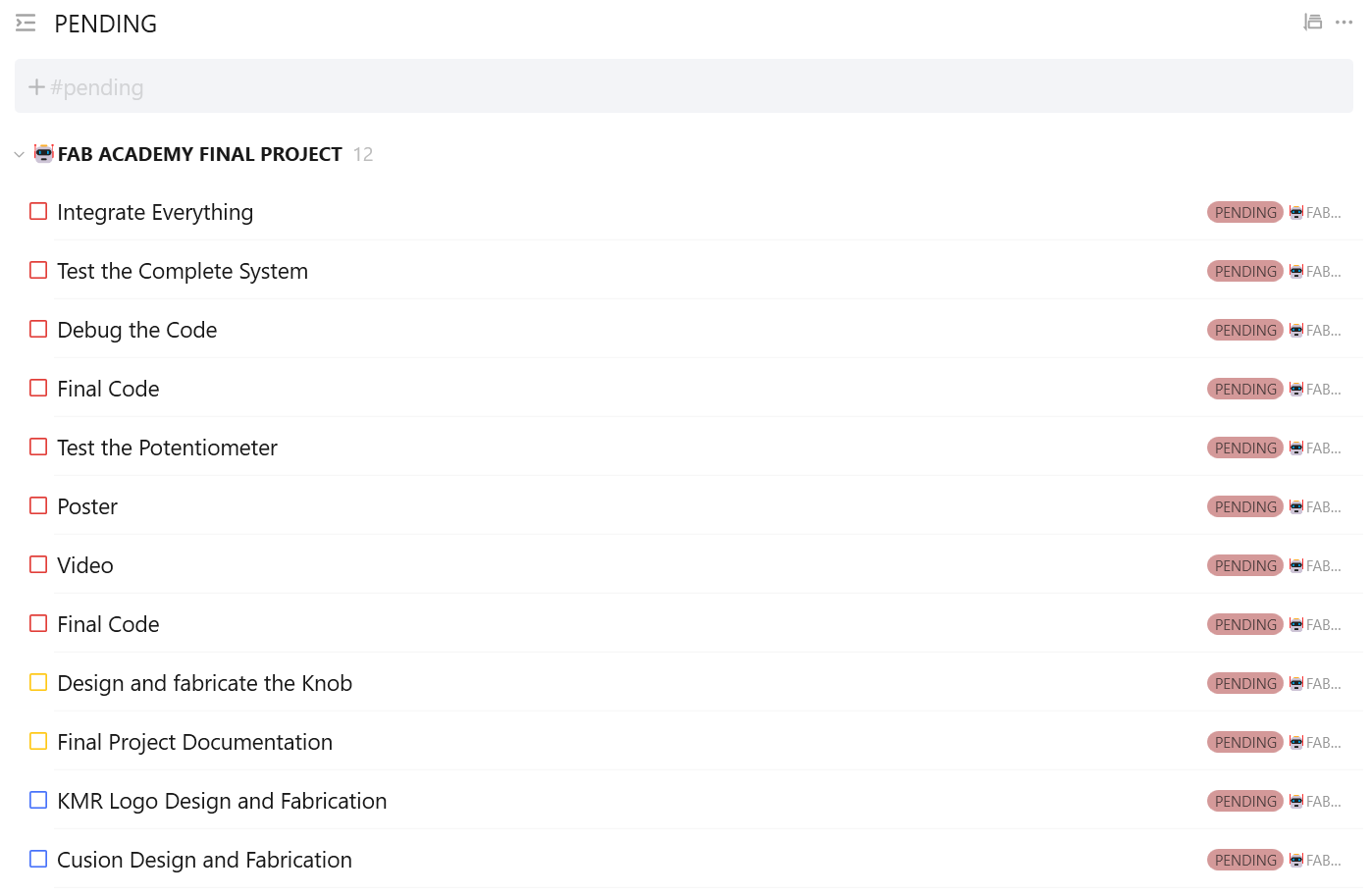
🚨
The image below illustrates the tasks that are pending.
What has Worked? what hasn’t?
✅
The CNC milling of the rocking chair has worked fine. This is one main part of the chair. However, I have faced a few challenges which I mentioned in the week 7 documentation linked below.
Rayan Abdul Gafoor - Fab Academy
© 2024 Rayan Abdul Gafoor. All rights reserved.
✅
The designing and production of the final PCB is completed and tested. Initially, I tested the board with the sample blink code. Then I tested the motor using the final board. It worked perfectly.
✅
I am also done with designing and fabricating the cases for the PCB and the MPU-6050.
❌
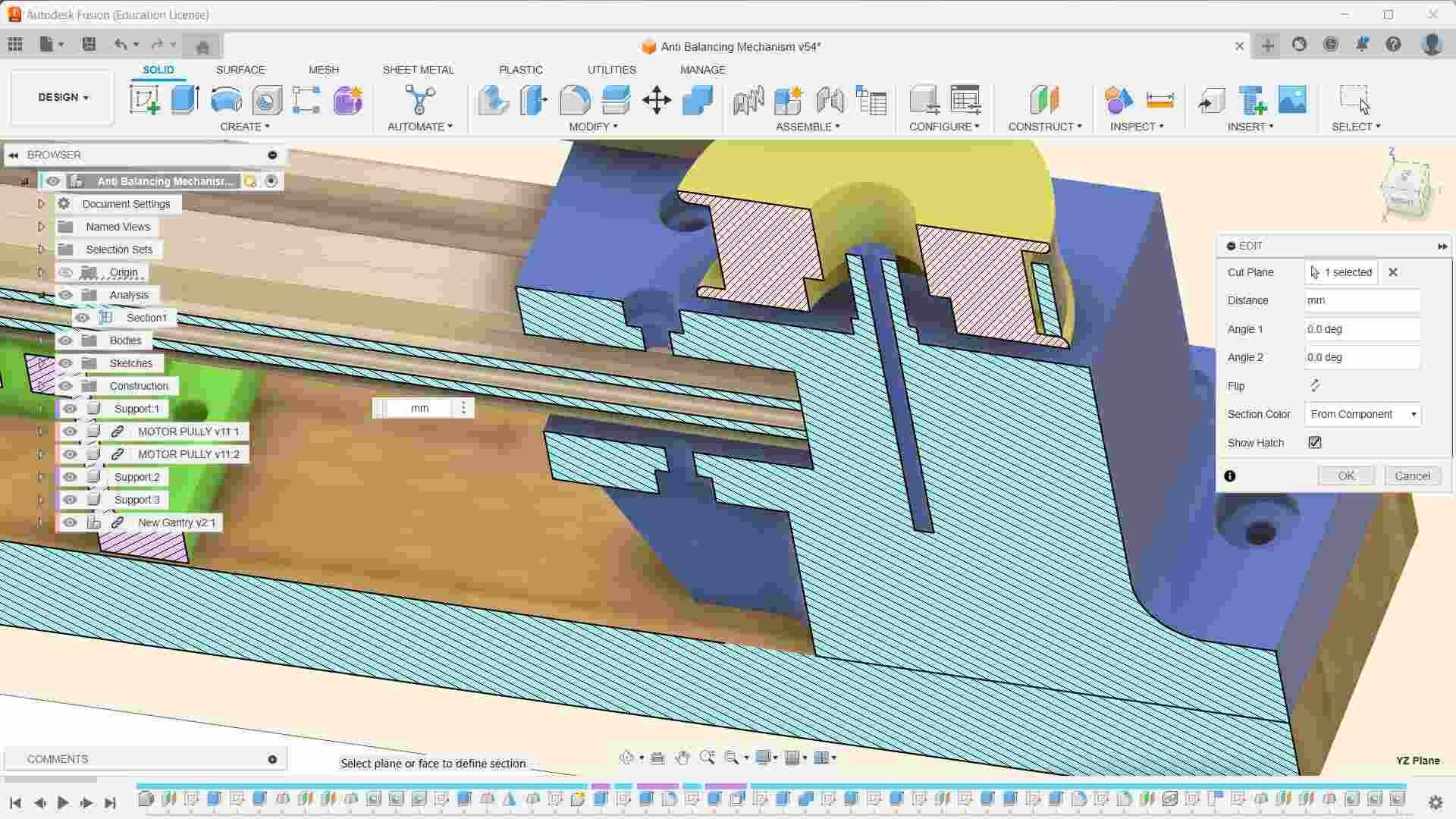
The linear mechanism fabrication still remains. However, the design parts need to be tested by splitting the required section from the main part that needs to be checked and printed to verify the design.
❌
The embedded programming phase still remains a question mark. Completing the remaining tasks is the only way to complete the programming phase. I need to fabricate the designed linear mechanism parts, and then I need to integrate them with the rocking chair to test and debug the code.
What questions need to be resolved?
⬇️
There are various questions that need to be resolved, which are wandering through my head. A Few of them are mentioned below.
📢
To mount the pulley, I decided to use a 3D-printed shaft and use a M3 bolt to screw all the way to the other end. I am not sure whether it would be enough to hold the pulley when the mass is moved.
📢
Another vital question that needs to be solved is whether auto-rocking could be achieved just by moving the mass or if I need to move it in synchrony with the movement of the rocking chair’s angle. Just by moving the mass, it won’t rock the chair. However, I need to verify it by testing.
📢
I also need to find the required amount of mass needed to move along the linear stage. This is also one of the vital parts of the project. In order to rock the chair, the required amount of mass must be sufficient to be moved along the linear stage.
📢
The programming phase is a bit more time-consuming, and there are subparts and programs that need to be tested to obtain the final code. This could only be achieved once the linear mechanism is successfully integrated into the main system.
📢
The programming phase is a bit more time-consuming and there are subparts and programs that need to be tested to obtain the final code. This could be only achieved once the linear mechanism is successfully integrated into the main system.
⬇️
Another question I need to be resolved is:
❓
How do I change the amplitude of the oscillation? 😵💫
❓
Does my application require an interface?🤔 While brainstorming about the project, I thought about developing an app or at least a web interface to control the system. Later, I realized that it was not necessary to build an interface to control the system and waste my valuable time.
What will happen when?
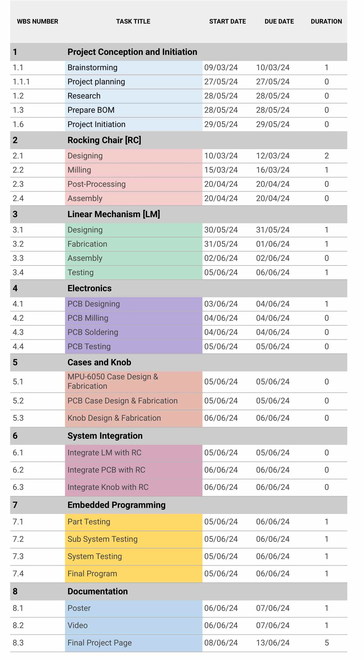
📋
The image below illustrates the Gantt chart of my final project.
What have you learned?
📢
This program helped me brush up on skills and provided me with the opportunity to challenge myself and go beyond my limits. Now, I am confident that this program will help me become the next version of myself. During the academy, I learned about the version control system. 2D and 3D design Electronics design and production. Explored various input and output devices. Various additive and subtractive fabrication processes. Embedded microcontroller interfacing and programming. System integration and packaging. This not only provided me with an opportunity to explore new methods and machines but also opened up new possibilities for digital fabrication.
📢
This is one of the projects where I pushed myself beyond my limits to be the next version of myself. I don't like to compete with anyone except one person, and that is me. I like to compete against my weaknesses. I found there are more challenges involved in this project, and I am excited to see how it goes 😊. This project helps me learn and solve real practical problems better than anything else.
✅
During the CNC milling of the rocking chair, I encountered a few challenges, and I got the opportunity to learn from my mistakes. First and foremost, I measured the thickness of the plywood from different sections of the plywood, and instead of taking the average, I chose the highest value. However, I manage to fit the parts, but it is recommended to take the average value of at least 8 values taken from 8 different sections of the plywood using a digital vernier.
✅
While arranging the parts in the Fusion 360 plugin, I gave a clearance of 20 mm between the parts, which is not sufficient for my case. After cutting the first part of my design, I realized this. Despite the tabs, the part started to vibrate, so I cut all of the parts to a depth of around 10 mm. To ensure their safety, I screwed them all to the sacrificial layer.
✅
During the CAM of the rocking chair, I used the auto-tab generation feature, and I found that the tabs were not properly placed. I removed all the tabs and placed the tabs manually.
✅
The design of the DC motor housing is pretty fun 🥲. The engineering drawing was not available to anyone. I had to completely rely on the digital vernier caliper to measure the holes and their distance from the reference lines.
📢
I am confident that I have implemented all of the knowledge I acquired during my previous week at the academy.
License I Chose
🔑
The work mentioned on this page is licensed under the Attribution-NonCommercial-ShareAlike 4.0 International (CC BY-NC-SA 4.0) license.