3D Printing & Scanning
Tasks for this week
Individual assignment:
- Design and 3D print an object (small, few cm3, limited by printer time) that could not be made subtractively.
- 3D scan an object (and optionally print it).
Group assignment:
- Test the design rules for your 3D printer(s).
3D Printing
3D printing is an additive manufacturing process. It is “additive” in the sense that it stacks and fuses layers of material rather than using a block of material or a mould to make physical objects. It can produce more complicated geometries than “conventional” technologies, is typically rapid, has cheap fixed setup costs, and a growing list of materials. The production of lightweight geometries and prototyping are two common uses for it in the engineering sector.
We can classify different manufacturing methods:
- Additive
- Subtractive
- Formative
- Additive manufacturing: This technique, involves building a part or product by adding material layer by layer. The material is usually a plastic, metal or composite material that is deposited in precise patterns to create the final object. Additive manufacturing is useful for creating complex geometries that are difficult or impossible to achieve using traditional manufacturing methods.
- Subtractive manufacturing: This technique involves removing material from a block or sheet of material to create the final product. CNC milling machines and lathes are examples of subtractive manufacturing technologies. Subtractive manufacturing is useful for creating complex shapes that cannot be produced using additive manufacturing methods.
- Formative manufacturing: This technique involves shaping or forming a material into a specific shape or form through processes such as forging, casting, or stamping. Formative manufacturing is commonly used in the production of metal parts and components.
3D printing, also known as additive manufacturing, entails fabricating three-dimensional objects from digital models through layering materials. This technology's popularity has surged over time owing to its capability to produce intricate geometries and bespoke components unattainable by conventional manufacturing methods.
The process of 3D printing commences with crafting a digital 3D model of the intended object using computer-aided design (CAD) software. Subsequently, the software divides the model into thin layers and generates a file containing instructions for the 3D printer. The printer then reads this file and proceeds to construct the object layer by layer, progressively adding material.
Various 3D printing technologies exist, such as Fused Deposition Modeling (FDM), Stereolithography (SLA), Selective Laser Sintering (SLS), and Digital Light Processing (DLP). Each of these methodologies employs distinct materials and techniques to produce the final object.
There are several types of 3D printing, which include:
- Stereolithography (SLA)
- Selective Laser Sintering (SLS)
- Fused Deposition Modeling (FDM)
- Digital Light Process (DLP)
- Multi Jet Fusion (MJF)
- PolyJet
- Direct Metal Laser Sintering (DMLS)
- Electron Beam Melting (EBM)
Fused Deposition Modeling (FDM)
Fused deposition modeling (FDM) is a common desktop 3D printing technology for plastic parts. An FDM printer functions by extruding a plastic filament layer-by-layer onto the build platform. It’s a cost-effective and quick method for producing physical models. There are some instances when FDM can be used for functional testing but the technology is limited due to parts having relatively rough surface finishes and lacking strength.
Stereolithography (SLA)
Stereolithography (SLA) is the original industrial 3D printing process. SLA printers excels at producing parts with high levels of detail, smooth surface finishes, and tight tolerances. The quality surface finishes on SLA parts, not only look nice, but can aid in the part’s function—testing the fit of an assembly, for example. It’s widely used in the medical industry and common applications include anatomical models and microfluidics. We use Vipers, ProJets, and iPros 3D printers manufactured by 3D Systems for SLA parts.
Selective Laser Sintering (SLS)
Selective laser sintering (SLS) melts together nylon-based powders into solid plastic. Since SLS parts are made from real thermoplastic material, they are durable, suitable for functional testing, and can support living hinges and snap-fits. In comparison to SL, parts are stronger, but have rougher surface finishes. SLS doesn’t require support structures so the whole build platform can be utilized to nest multiple parts into a single build—making it suitable for part quantities higher than other 3D printing processes. Many SLS parts are used to prototype designs that will one day be injection-molded. For our SLS printers, we use sPro140 machines developed by 3D systems.
PolyJet
PolyJet is another plastic 3D printing process, but there’s a twist. It can fabricate parts with multiple properties such as colors and materials. Designers can leverage the technology for prototyping elastomeric or overmolded parts. If your design is a single, rigid plastic, we recommend sticking with SL or SLS—it’s more economical. But if you’re prototyping an overmolding or silicone rubber design, PolyJet can save you from the need to invest in tooling early in the development cycle. This can help you iterate and validate your design faster and save you money.
Digital Light Processing (DLP)
Digital light processing is similar to SLA in that it cures liquid resin using light. The primary difference between the two technologies is that DLP uses a digital light projector screen whereas SLA uses a UV laser. This means DLP 3D printers can image an entire layer of the build all at once, resulting in faster build speeds. While frequently used for rapid prototyping, the higher throughput of DLP printing makes it suitable for low-volume production runs of plastic parts.
Multi Jet Fusion (MJF)
Similar to SLS, Multi Jet Fusion also builds functional parts from nylon powder. Rather than using a laser to sinter the powder, MJF uses an inkjet array to apply fusing agents to the bed of nylon powder. Then a heating element passes over the bed to fuse each layer. This results in more consistent mechanical properties compared to SLS as well as improved surface finish. Another benefit of the MJF process is the accelerated build time, which leads to lower production costs.
Metal 3D Printing Processes
Direct Metal Laser Sintering (DMLS)
Metal 3D printing opens up new possibilities for metal part design. The process we use at Protolabs to 3D print metal parts is direct metal laser sintering (DMLS). It’s often used to reduce metal, multi-part assemblies into a single component or lightweight parts with internal channels or hollowed out features. DMLS is viable for both prototyping and production since parts are as dense as those produced with traditional metal manufacturing methods like machining or casting. Creating metal components with complex geometries also makes it suitable for medical applications where a part design must mimic an organic structure.
Electron Beam Melting (EBM)
Electron beam melting is another metal 3D printing technology that uses an electron beam that's controlled by electromagnetic coils to melt the metal powder. The printing bed is heated up and in vacuum conditions during the build. The temperature that the material is heated to is determined by the material in use.
Lets Design
So for the assignment purpose (Design and 3D print an object that could not be made subtractively i choose Fusion 360.
Firstly, I began by creating a sphere as the base of my object.
.png)
Following this, I proceeded to draw a torus and applied a circular pattern to it, integrating it into the design.
.png)
.png)
Upon completing the design, I exported it in .stl format to prepare for the 3D printing process.
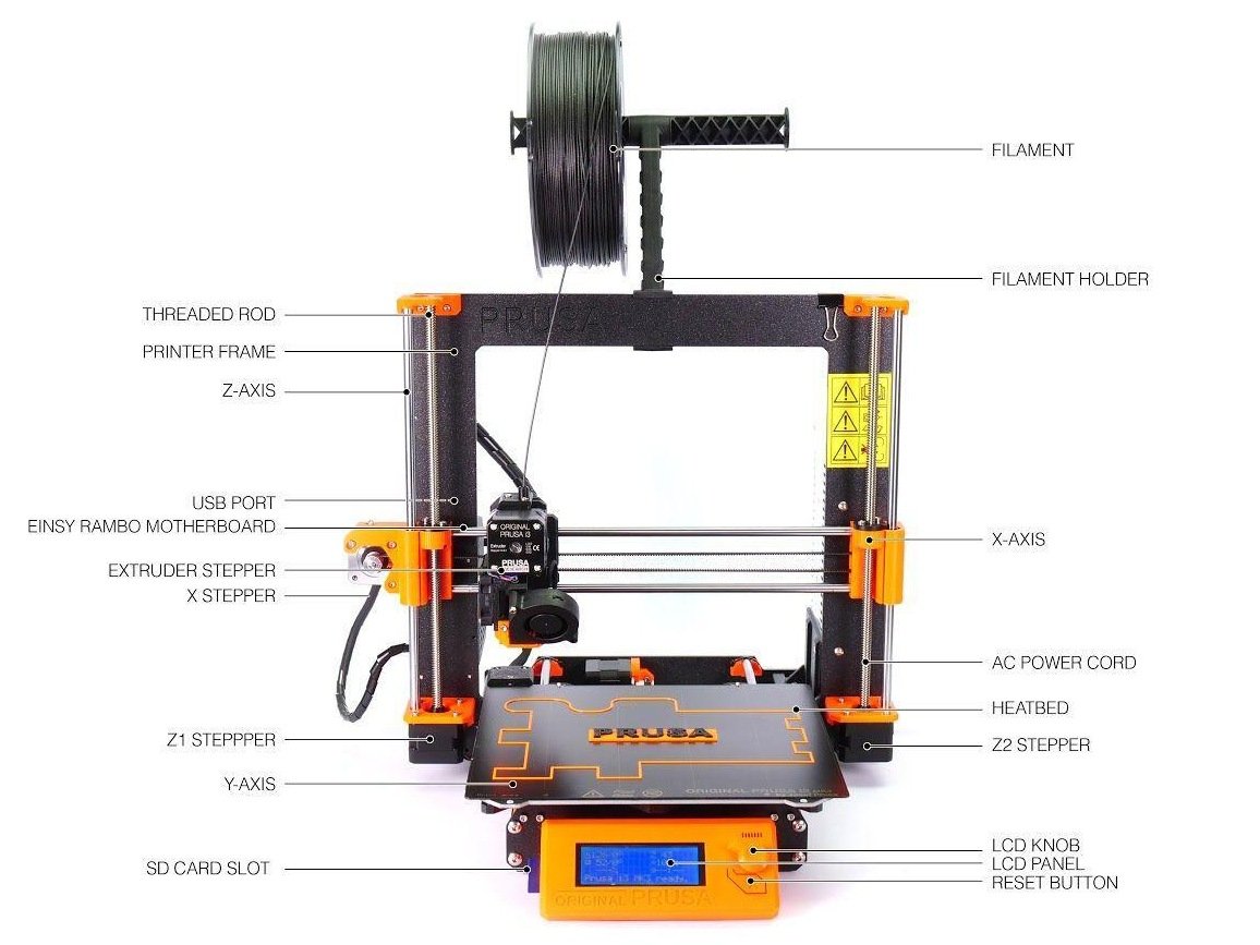
Prusa i3 MK3S
The Prusa i3 MK3S presents a wealth of advanced functionalities tailored for 3D printing enthusiasts. Utilizing FDM (Fused Deposition Modeling) technology, this printer excels in precision, boasting a remarkable capability to print layers as fine as 0.05 mm in height. Its generous build volume spans 250 x 210 x 210 mm, accommodating a diverse range of printing projects.
A standout feature of the printer is its sophisticated auto bed leveling system, ensuring optimal print bed alignment and nozzle positioning for each print. This results in consistently accurate prints with minimal user intervention.
Enhancing user experience, the printer is equipped with a filament sensor that detects filament depletion, halting printing automatically to allow seamless filament replacement without disrupting the print job.
Compatibility with the open-source Prusa Slicer software empowers users with extensive customization options and flexibility throughout the printing process.
Moreover, the printer's versatility extends to its ability to handle various materials, including PLA, ABS, PETG, and TPU, providing users with ample choices to suit their specific printing needs.
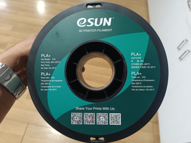
The chosen material for printing is PLA (Polylactic Acid), a widely-used thermoplastic polymer in 3D printing. PLA is known for its biodegradable nature, being derived from renewable sources such as cornflour, sugarcane, and cassava. It offers simplicity in printing and doesn't require a heated print bed, although pre-heating the bed to 60 to 80℃ is recommended. Printing temperature for PLA typically ranges between 205-225℃. Thanks to its low warping and shrinkage properties during printing, PLA results in less distortion and greater printing accuracy. Additionally, PLA is available in a wide array of colors and can be easily painted or finished to achieve desired aesthetics
Now it's time to initiate the 3D printing process. Unlike traditional 2D printing, 3D printing involves several preparatory steps before instructing the machine. The foremost consideration is the file format. As previously mentioned, the printer operates solely on G-Code, thus requiring our model to be exported in STL format. Given our use of a Prusa machine, this file is then opened using Prusa Slicer software.
Each 3D printer necessitates its own software to generate G-code.
Step 1: Begin by installing the Prusa Slicer software.
We can preset the printer by adding the printer
.png)
.png)
Step 2: Import the STL file into Prusa Slicer, either through the software's import function or by directly dragging and dropping the file into the Prusa Slicer window.
.png)
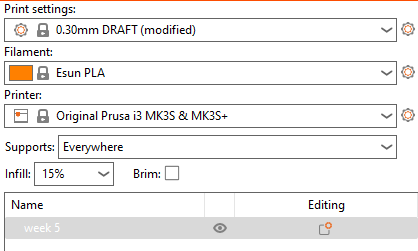
Step 3: Familiarize yourself with the Prusa Slicer interface. Basic tools are located on the left side, including Move, Rotate, and Place on Face. At the top, options like Add, Delete, and Arrange are available. On the right side, printer settings and filament type selection can be found.
Printer Select proper printer we had prusa mk3s+ ( Original Prusa i3 mk3s+)
Support - This allows you to generate support structures for overhangs and other complex features in your print.
Infill - This determines how much of the interior of your print will be filled with material, affecting the print strength and weight.
filament - A 3D printer filament is like a super-long and super-thin piece of plastic spaghetti . It comes in all sorts of colors and can be fed into a 3D printer. The printer then melts the filament and uses it to create a 3D object, layer by layer
Step 4: Once all parameters are finalized, it's time to slice the model. It's crucial to remember to add supports before slicing. The chosen material for printing is PLA (ESUN Brand).
.png)
Step 5: After slicing, the preview will showcase the outcome. If everything looks satisfactory, the next step is to export the G-Code to a memory card.
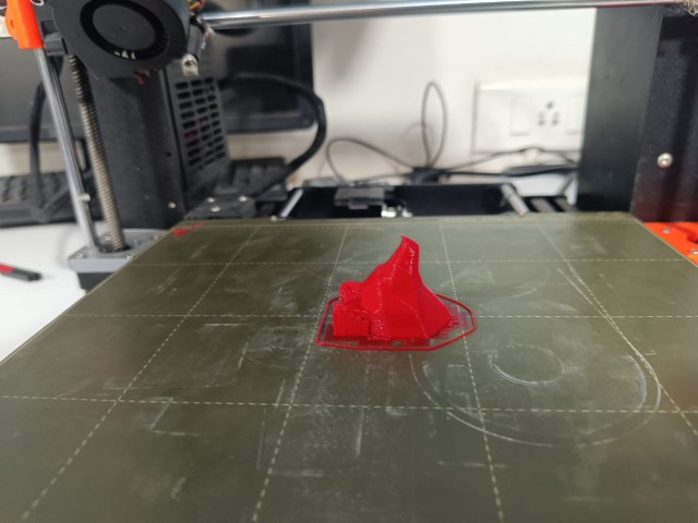
Results
Group Assignment
Test the design rules for your 3D printer(s).
.jpeg)
click on the link -Group Assignment-Week 5
3d Scanning
What is 3d Scanning ?
3D scanning is the process of capturing the shape and appearance of real-world objects and creating a digital 3D model from that data. It is typically done using a 3D scanner, which can use various technologies such as laser, structured light, or photogrammetry to capture the object's geometry, texture, and color.
3D scanning entails the process of capturing the shape and geometry of a physical object in three dimensions through specialized equipment. Various technologies and methodologies exist for 3D scanning, including structured light scanning, laser scanning, and photogrammetry. Each of these methods employs distinct approaches to capture the object's form and structure.
Artec leo
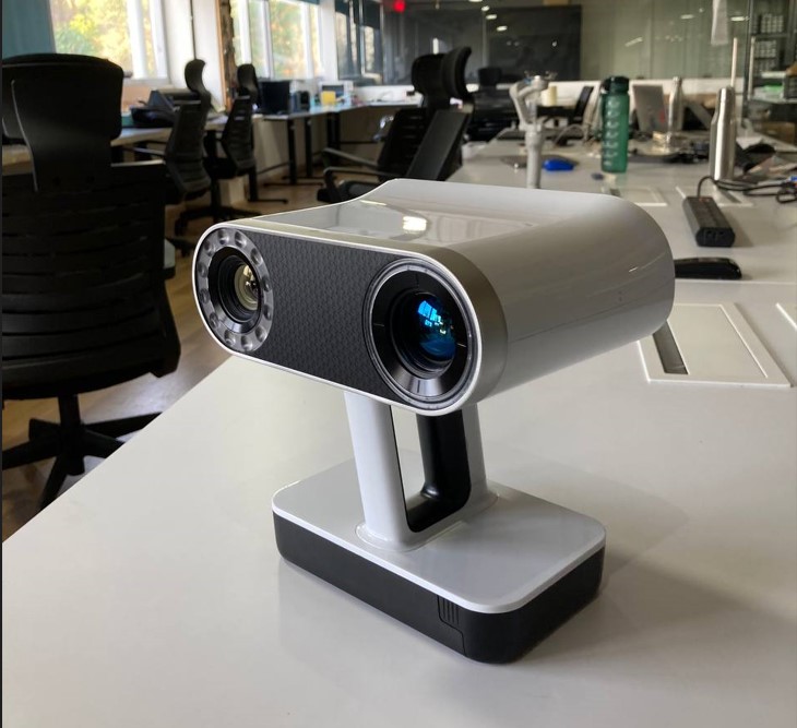
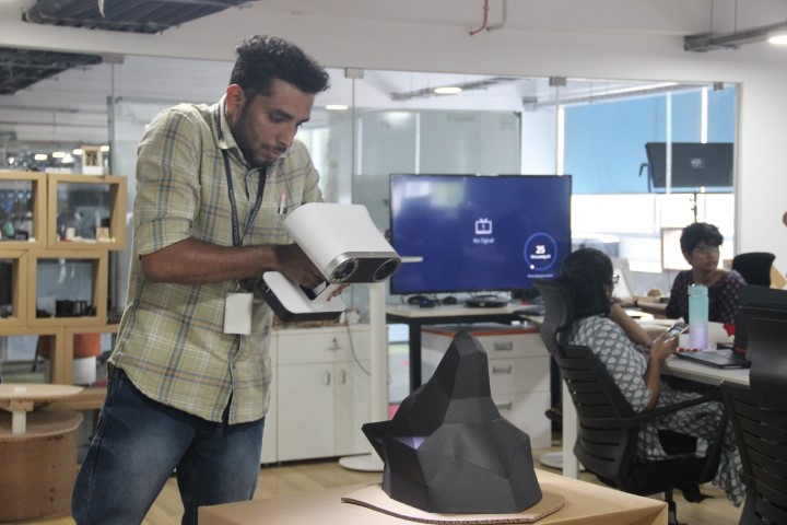
In our laboratory, we utilize an Artec Leo 3D scanner. It is one of the most advanced 3D scanners available on the market today, and it is known for its ease of use and fast scanning capabilities.This handheld, portable device is engineered for swift and precise scanning of diverse objects, ranging from human subjects to mechanical components. Equipped with an integrated touchscreen and onboard computer, the Artec Leo 3D scanner facilitates real-time scanning and 3D model processing sans the requirement for an external computer. It leverages structured light scanning technology to produce high-resolution 3D scans with an accuracy of up to 0.1mm.
Structured light scanning functions by projecting a specific light pattern onto the object and then employing cameras to record the distortions within the pattern induced by the object's contours. Artec Leo is developed by the Luxembourg-based company Artec 3D.
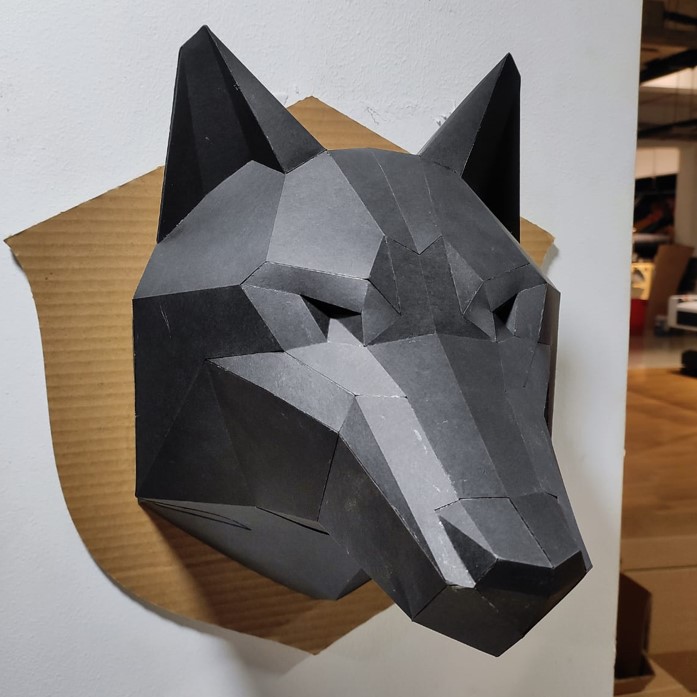
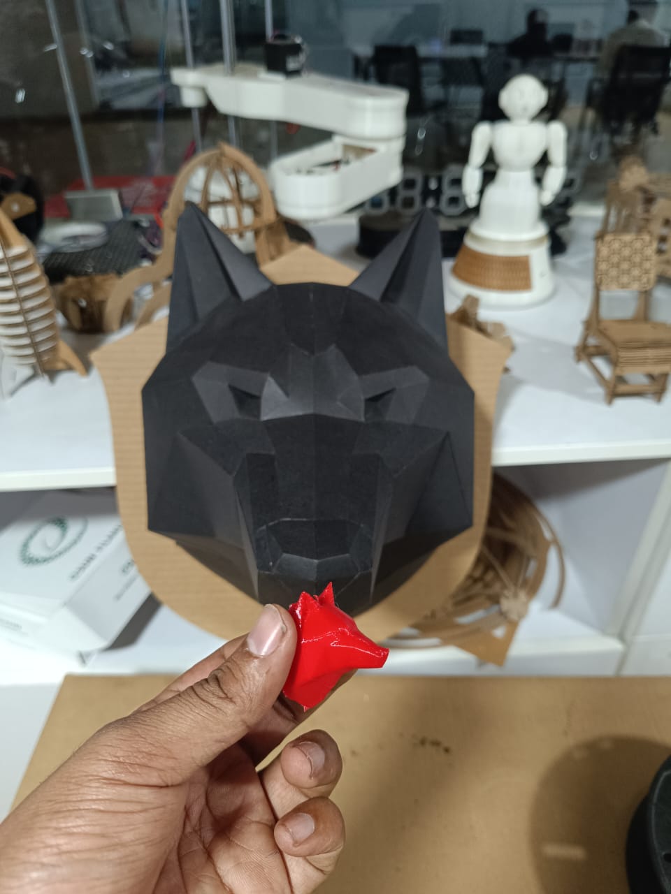
I had this idea to scan Ajith's (Our Previous Intern) polygon paper wolf head which he created on Zund.
The process starts by adding a new project. After adding the new project, focus the camera on the thing you want to scan. Once the object is visible on the screen, pressing the record button will begin the scanning process. Now move all around the object to thoroughly scan it. A parabola-like action with an upward and downward wiggle can produce positive results.

.jpeg)
.jpeg)
Artec Studio
Once the scanning is finished, it must be processed before the final result is presented. Artec Studio 15 Professional software is used for that. The process is as follows.
Artec Studio is a software developed by Artec 3D, The software is designed to help users create, process, and edit 3D models from data acquired with Artec 3D scanners.
Artec Studio provides advanced features for creating high-quality 3D models, including automatic alignment and merging of scan data, tools for removing unwanted geometry and optimizing mesh, and texture mapping. The software also includes a range of export options, allowing users to save their models in a variety of file formats, including STL, OBJ, PLY, and VRML.
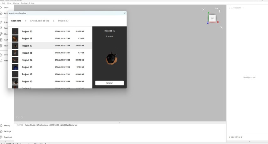
Step 1: Import The file from the scanner. Connect the scanner to the PC and import directly from the scanner using Artec Studio.
.png)
Step 2: Once connected, it shows the list of files saved in the machine. Select our model from list and import it to PC.
Step 3 :Use Auto Pilot feature to merge all these into a single model. This can be done manually also.
.png)
Step 4: Now we can edit using Editor to fix the missing features and unwanted things.
Use
Eraser to erase unwanted objects that was captured. Use Lasso tool to select the objects and erase it.
.png)
Step 5:Use Registration & Fusion for smoothening the object. Once this is done, Use Postprocessing for filling holes & simplify mesh. We can fill holes manually also.
Registration: This tool aligns multiple scans into a single model using common features, such as edges or corners. I clicked global registration on my model .
Fusion feature in Artec Studio works by aligning and merging multiple scans using common features and then applying advanced algorithms to blend overlapping areas of the scans and fill in any missing data.
I chose Smooth Fusion, to create a more accurate ,seamless and smooth representation of the object.
.png)
Step 6:We can do the Hole Filling manually also for getting better results.
.png)
Step 7 :Texture mapping is the process of applying a texture to a 3D model, allowing it to appear more realistic and visually appealing. Click on texture from the left tool bar and click apply .
.png)
Finally a texture tool crated the appearance of a real-world texture. you cad adjust the brightness , saturation , hue and contrast and gama correction using sliders.
.png)
And finally click on file to export the file to Mesh fomat ( obj ,step etc )
Finally 3d image of my scan .
%201.png)
Finally I imported the .obj in to prusa slicer
The slicer settings i have used for printing
Files
- 3D Design Fusion File-Click here
- Scanned OBJ File-Click here