Input Devices
Tasks for this Week
Individual Assignment : Measure something: Add a sensor to the microcontroller board that you have designed and read it
Group Assignment: Probe an input device's analog levels and digital signals
For this week Individual assignment I attempted the Step Response sensor.
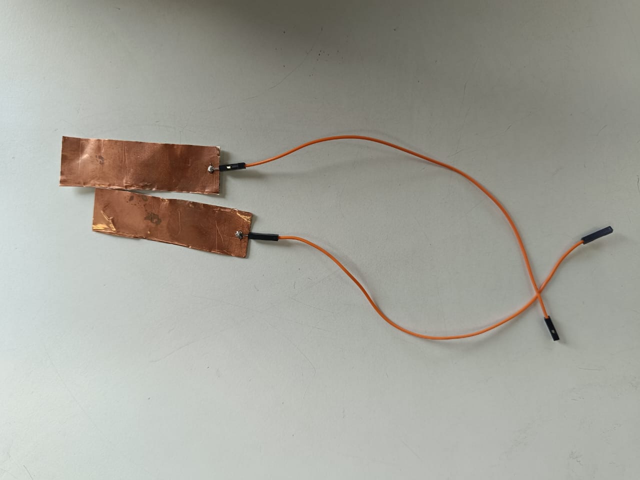
The step-response is a sensor that is made with two sheets of copper, separated from each other by a porous insulating material. It can be used to calculate the value of force, weight, resistance.
Working Principle
- When a voltage (potential difference) is applied across the capacitor's plates, an electric field forms across the dielectric.
- Electrons accumulate on the negative plate, creating a negative charge.
- An equal amount of positive charge is induced on the opposite plate due to the electric field.
- The dielectric material prevents charges from directly crossing between plates, enabling the capacitor to store energy in the electric field.
Capacitive Sensing
Capacitive sensing is a technology that detects the presence, position, and proximity of objects by measuring changes in capacitance. It leverages the principle that the capacitance of a system changes when a conductive or dielectric object is nearby. This technology is widely used in touch screens, proximity sensors, and other applications where non-contact detection is advantageous.
Working
- A capacitive sensor consists of two conductive electrodes separated by an insulating material (dielectric).
- When an object (like a finger) approaches or touches the sensor, it alters the electric field between the electrodes, changing the capacitance.
- The dielectric, an insulating material between the electrodes, can be air, glass, or any other insulator.
Types of Capacitive Sensors
- Self-Capacitance: Measures the capacitance of a single electrode with respect to ground. Commonly used in touchscreens and simple touch buttons.
- Mutual Capacitance: Measures the capacitance between two electrodes. Used in multi-touch screens to detect interactions from multiple fingers simultaneously.
Capacitive Multitouch
Creating a capacitive multitouch sensor involves designing a grid of conductive material to detect multiple touch points at once. This technology is used in modern touchscreens found in smartphones, tablets, and other interactive devices.
The step-response is a sensor that is made with two sheets of copper, separated from each other by a porous insulating material. It can be used to calculate the value of force, weight, resistance... I have followed Robert Hart's tutorial as well as Neil's examples.
A series of pulses is sent through the TX electrode, which, depending on the material between the two electrodes, allows more or less that series of pulses to pass. In the following graph you can see how it works. The other electrode will be connected between two resistors, one for pull-up and the other for pull-down and to an analog input.
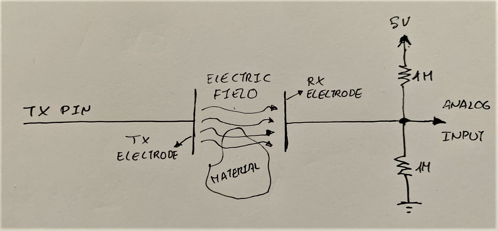
Microcontroller
Based on the different microcontrollers we used, we could connect the TX and RX into different pins. In the Step Responsee sensor case, we need an analog pin to send and receive the pulse. So in ATtiny1614 i have chosen 2 analog pins.
.jpg)
PCB Design
While designing the PCB i have referred to Neil's documentation from week 11.
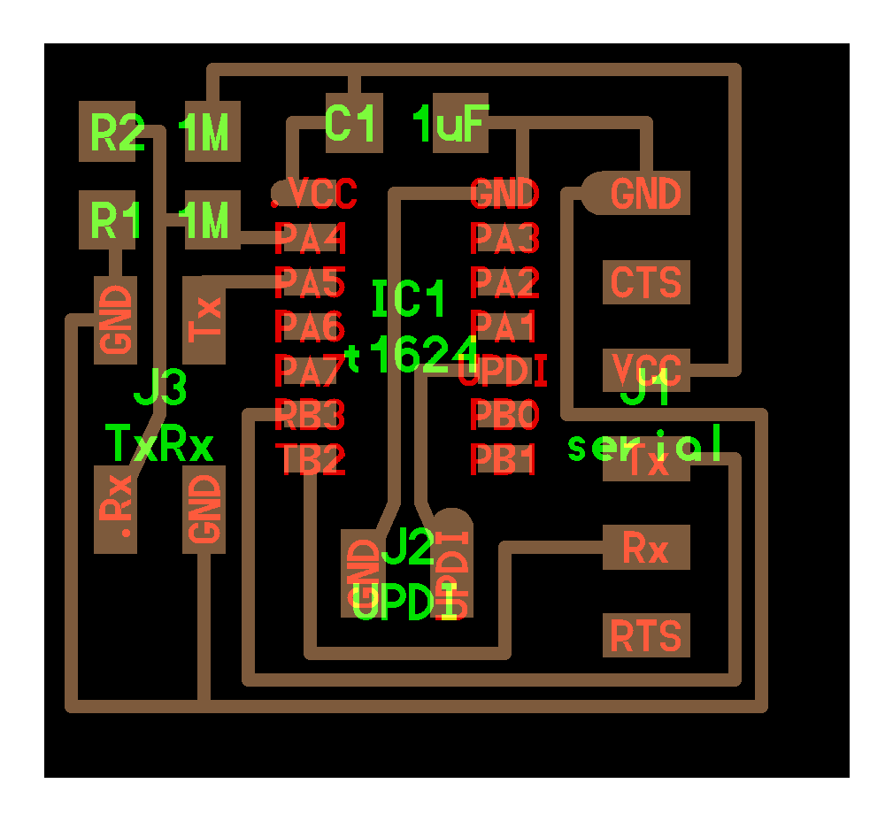
I use KiCad to draw the circuit diagram which i have studied on week 8
.png)
.png)
After milling i have soldered the components
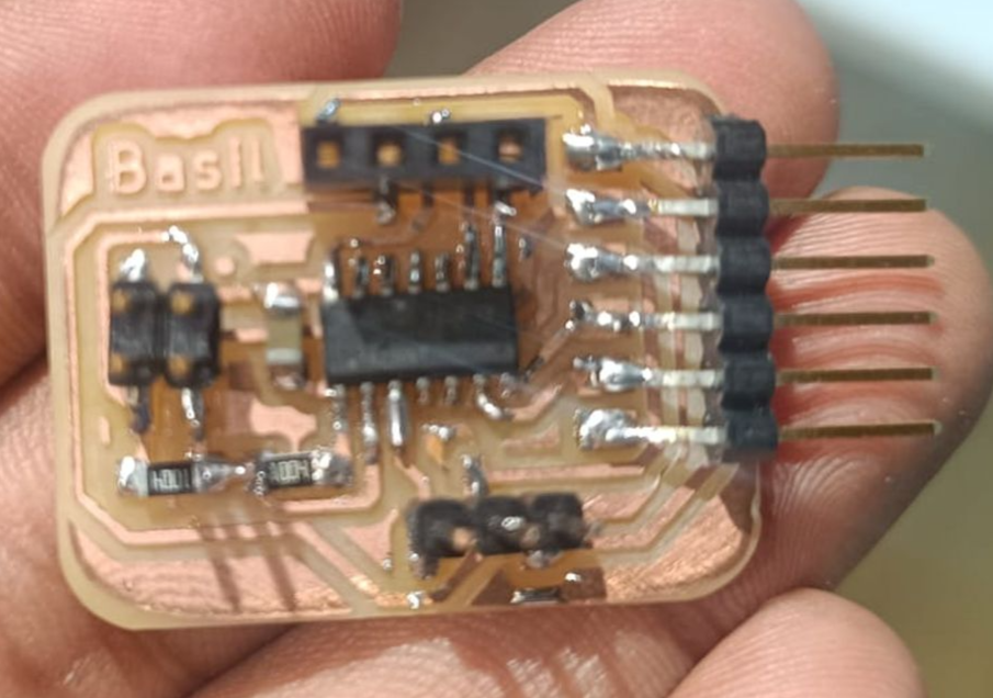
For step response i have soldered a small piexe of copper sheet for conneting to my PCB.
Problem Encountered
During the soldering process, I encountered a significant issue where two paths on the PCB were shorted, causing an electrical connection that should not have been there. This short circuit prevented the board from functioning as intended and posed a risk to the components and equipment.
Problem Identification:
To identify the source of the short circuit, I used a Lynx EVO Stereo Microscope, which provided a high-resolution view of the PCB. Upon inspection, I found that excess solder had bridged two adjacent paths, creating the unintended connection. This error was likely due to a combination of insufficiently controlled soldering and the close proximity of the paths on the PCB.
Resolution:
To resolve the issue, I took the following steps:
- Removal of Excess Solder: Using a soldering iron and a desoldering braid, I carefully removed the excess solder causing the short circuit. This step required careful attention to avoid damaging the surrounding components or the PCB itself.
- Re-soldering: Once the short was cleared, I resoldered the connections with greater precision. I used a fine-tip soldering iron and ensured that the solder was applied only where necessary, avoiding excess buildup.
- Re-inspection: After re-soldering, I used the Lynx EVO Stereo Microscope to re-inspect the area for any further issues. This thorough check confirmed that the short circuit had been eliminated and all connections were properly soldered.
- Functional Testing: Finally, I tested the PCB to ensure that it was functioning correctly. The test results indicated that the board was operating as expected, confirming that the short circuit had been resolved.
Programming
For programming the board i have already bootloaded program for ATtiny 1614 in Output Week .So for step response i have used Neils code for the programming.
//
	// hello.txrx.t1624.ino
	//
	// ATtiny1624 step response
	//
	// Neil Gershenfeld 11/14/21
	//
	// This work may be reproduced, modified, distributed,
	// performed, and displayed for any purpose, but must
	// acknowledge this project. Copyright is retained and
	// must be preserved. The work is provided as is; no
	// warranty is provided, and users accept all liability.
	//

	#define rxpin 0      // receive pin
	#define txpin 9      // transmit pin
	#define settle 100   // settle time
	#define samples 100  // number of samples to accumulate

	void setup() {
	  Serial.begin(115200);     // start serial
	  pinMode(txpin, OUTPUT);   // set transmit pin to output
	  analogSampleDuration(5);  // speed up ADC sampling
								//  analogReadResolution(12); // increase ADC resolution
	}

	void loop() {
	  int32_t up, down;
	  up = down = 0;
	  noInterrupts();  // disable interrupts while measuring
	  for (int i = 0; i < samples; ++i) {
		digitalWriteFast(txpin, HIGH);  // charge up
		up += analogRead(rxpin);        // read
		delayMicroseconds(settle);      //settle
		digitalWriteFast(txpin, LOW);   // charge down
		down += analogRead(rxpin);      // read
		delayMicroseconds(settle);      // settle
	  }
	  interrupts();               // enable interrupts after measuring
	  Serial.println(up - down);  // send difference
	  Serial.flush();             // finish communicating before measuring
	}
we can see the change in analog values . So when the value increases we can understand that there is a toch occurs. The video clearly indicate the results.
//
		#
# hello.txrx.t1624.py
#
# receive and display transmit-receive step response
#    hello.step.t1624.py serial_port
#
# Neil Gershenfeld 11/14/21
#

from tkinter import *
import serial,sys

WINDOW = 600 # window size
max = 75000 # bargraph max
eps = 0.1 # filter fraction
filt = 0.0 # filtered value

def idle(parent,canvas):
   global filt, eps
   #
   # idle routine: read, filter, and plot
   #
   value = int(ser.readline().rstrip().decode())
   filt = (1-eps)*filt + eps*value
   x = int(.2*WINDOW + (.9-.2)*WINDOW*filt/max)
   canvas.itemconfigure("text",text="%.0f"%filt)
   canvas.coords('rect1',.2*WINDOW,.05*WINDOW,x,.2*WINDOW)
   canvas.coords('rect2',x,.05*WINDOW,.9*WINDOW,.2*WINDOW)
   canvas.update()
   parent.after_idle(idle,parent,canvas)

#
#  check command line arguments
#
if (len(sys.argv) != 2):
   print("command line: hello.txrx.t1624.py serial_port")
   sys.exit()
port = sys.argv[1]
#
# open serial port
#
ser = serial.Serial(port,115200)
ser.setDTR()
#
# set up GUI
#
root = Tk()
root.title('hello.txrx.t1624.py (q to exit)')
root.bind('q','exit')
canvas = Canvas(root, width=WINDOW, height=.25*WINDOW, background='white')
#
canvas.create_text(.1*WINDOW,.125*WINDOW,text="1",font=("Helvetica", 24),tags="text",fill="#0000b0")
canvas.create_rectangle(.2*WINDOW,.05*WINDOW,.3*WINDOW,.2*WINDOW, tags='rect1', fill='#b00000')
canvas.create_rectangle(.3*WINDOW,.05*WINDOW,.9*WINDOW,.2*WINDOW, tags='rect2', fill='#0000b0')
canvas.pack()
#
# start idle loop
#
root.after(100,idle,root,canvas)
root.mainloop()
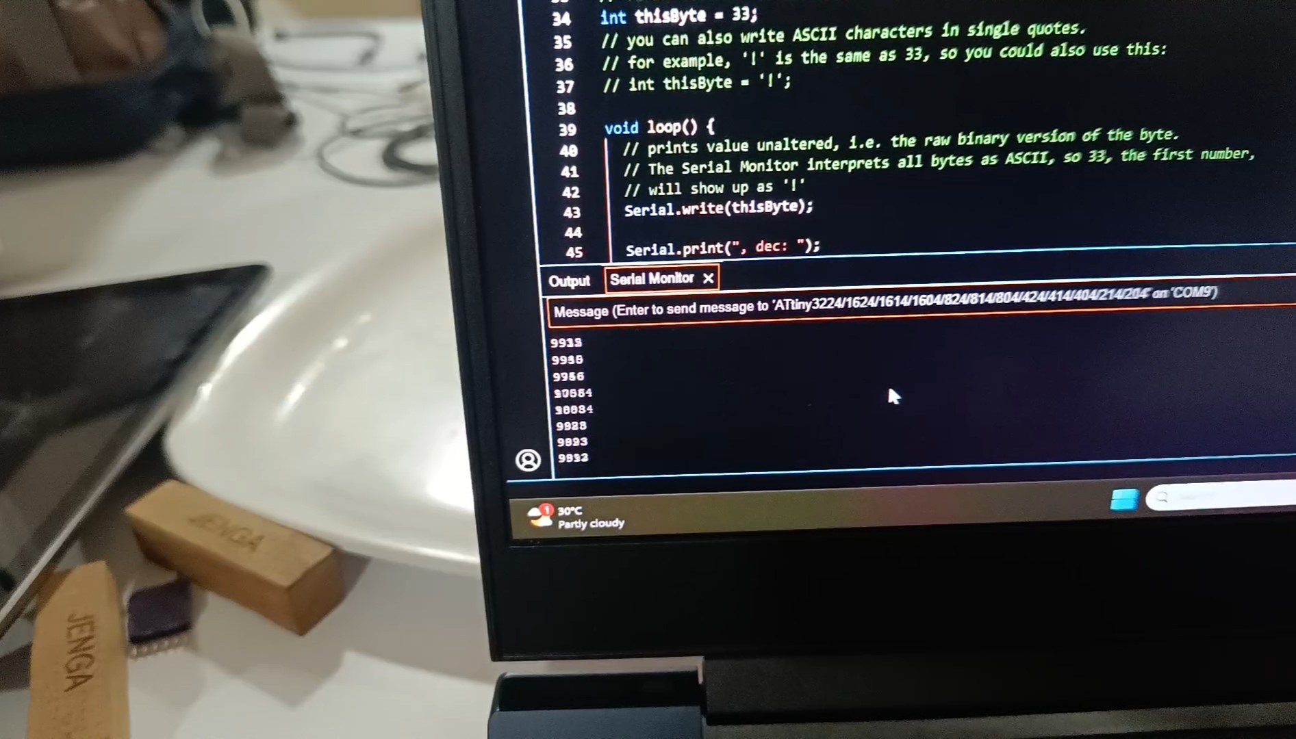
I got a wonderful result for step response
The program measures the capacitive step response by charging and discharging a capacitor connected to specific pins. The txpin is set high to charge the capacitor, and the voltage is read using analogRead(rxpin). After a short delay, the txpin is set low to discharge the capacitor, and the voltage is read again. This process is repeated 100 times to accumulate readings for both charging and discharging. The difference between these accumulated readings is calculated and displayed on the Serial Monitor, showing a stream of values that represent the capacitive step response. The values depend on the sensor's capacitance and the environment, with higher values indicating higher capacitance, which could be due to closer or more significant object proximity to the sensor.
the Serial Monitor will display numerical values representing the difference in analog readings during the charging and discharging cycles of the capacitor connected to your sensor. These readings give insight into the capacitive properties and changes in the environment or sensor contact.
we can see the change in analog values . So when the value increases we can understand that there is a toch occurs. The video clearly indicate the results.
Group Assignment
This week's group assingment was to probe an input device's analog levels and digital signals. We chose Hall Effect sensor as the input device.
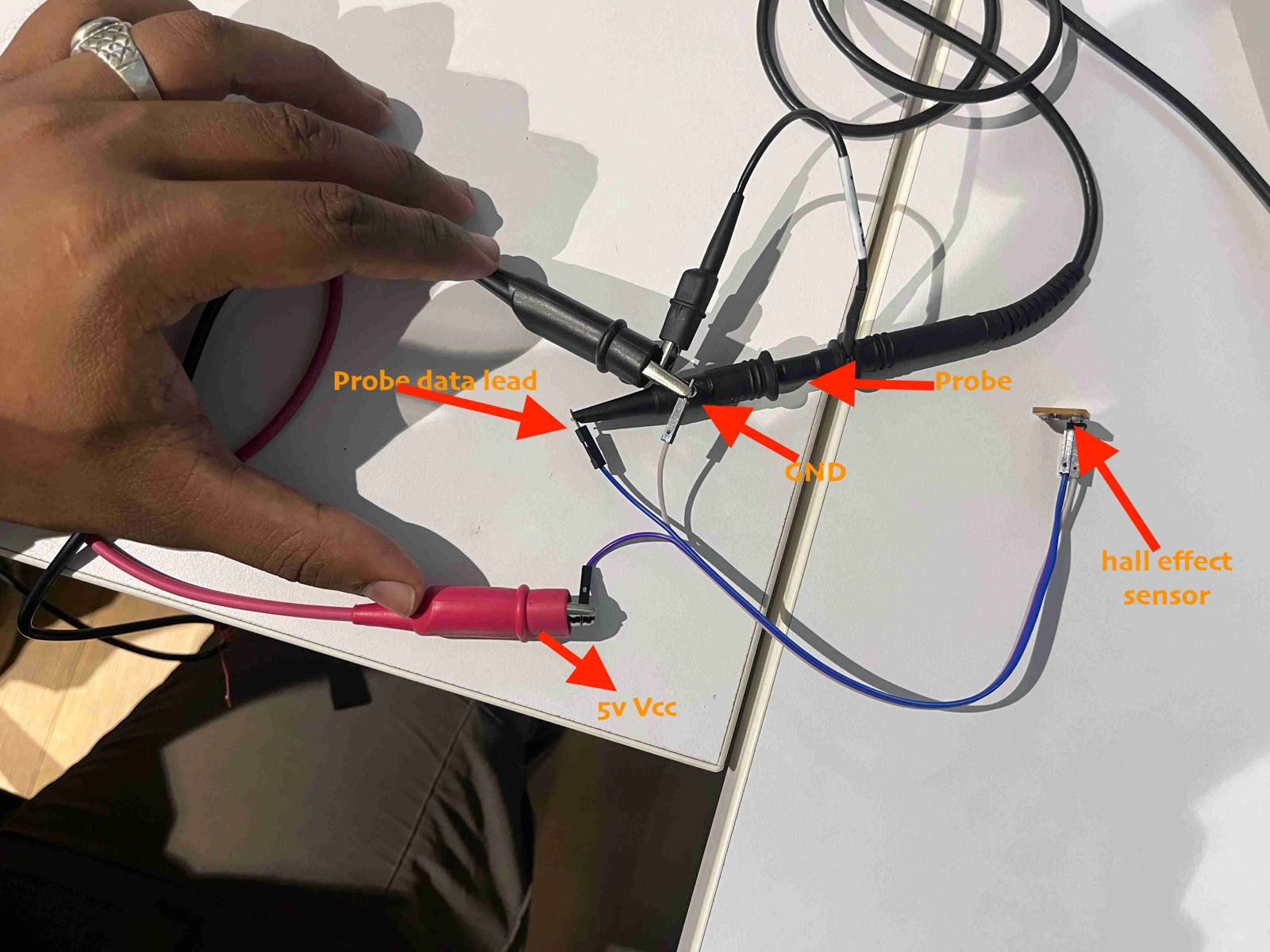
For further details, Group Assignment-Week 11