Data Sheets
For this week's group assignment, we were tasked with reviewing the safety data sheets for each of our molding and casting materials, then making and comparing test casts with each of them.
NEUKADUR PROTOCAST 105 Data sheet review
Main characteristics:
- Very good flowability
- Very impact resistant
- Very good colorability
- High heat resistance
- Cures to white color
- Only suitable for vacuum casting
| Component | Color | Mixing Ratio by Weight | Density (20°C) g/cm³ | Viscosity (25°C) mPa∙s |
|---|---|---|---|---|
| NEUKADUR ProtoCast 105 Component A | Slightly yellowish | 100 | 1.05 | 650 |
| NEUKADUR ProtoCast 105 Component B | Slightly yellowish | 200 | 1.16 | 160 |
| Mixture Properties (approximate values) | PC 105 A / PC 105 B |
|---|---|
| Mixing Viscosity (25°C) mPa∙s | 325 |
| Density (20°C) g/cm³ DIN 53479 | 1.13 |
| Processing Time (25°C) Minutes | 5 |
| Demolding Time (70°C) Minutes | 60 |
| Hardness Shore D DIN 53505 after storage 2 Hours at 70°C | 82 |
| Cured Color | White |
| Recommended Layer Thickness mm | 5 |
processing:
"NEUKADUR ProtoCast 105 Component A has to be homogenized thoroughly prior to processing. Tightly close receptacles after every use. After 30 – 60 minutes, the cured material has not yet got its full impact strength (the same is only obtained after approx. 1 - 2 hours at 70 °C) so that demoulding should be made with care, particularly when it deals with thin parts. We recommend pouring NEUKADUR ProtoCast 105 Comp. A/B into moulds having been preheated to 70°C (e. g. of ProtoSil RTV 240) and tempering the compound for at least 1 hour at 70°C before demoulding. Recommended thickness of cast layer: up to max. 5 mm Furthermore, we recommend evacuating NEUKADUR ProtoCast 105 Comp. A for 15 minutes at the highest possible vacuum, then releasing the same to 20 – 25 mbar before adding NEUKADUR ProtoCast 105 Comp. B. At < 20 mbar, heavy foaming may occur at the moment when both components are poured together."
PROTOSIL RTV 245
Main characteristics:
- Shore hardness A 40
- very good flow properties, translucent
- shrinkage-free vulcanization at room temperature
- can be made thixotropic
- high resistance to initial tearing and tear propagation
| Properties in the non-crosslinked state | ProtoSil RTV 245 Comp. A | ProtoSil RTV 245 Comp. B 1 (dry surface) |
ProtoSil RTV 245 Comp. B 2 (oily surface) |
NEUKASIL Thixotropic Agent SN 200 |
|---|---|---|---|---|
| Colour | colourless | colourless | colourless | colourless |
| Mixing ratio p.b.w. | 100 | 10 | 10 | 0.1 – 0.3 |
| Density 20 °C (approx.) g/cm3 | 1.1 | 0.95 | 0.96 | 0.98 |
| Viscosity 20 °C (approx.) mPa·s | 60,000 | 320 | 400 | 1,000 |
| Properties of the mixture (approx. values) | Mixture A/B |
|---|---|
| Mixed viscosity | 35,000 mPa·s |
| Pot life (1000 g) | 80 minutes |
| Demouldable after | 12 hours |
| Shore A hardness points | DIN 53505 40 |
| Service temperature | 200 °C |
processing:
See that as little air as possible gets into the compound while stirring. To obtain a bubble-free vulcanized material, we recommend evacuating the crosslinker-containing formulation before continuing the processing. When the vacuum is created, the mixture may expand by 3 - 4 times of its original volume under formation of bubbles. The process is finished when the bubbles have collapsed and the formulation has reobtained its original volume. Carefully pour the prepared material over the object to be cast
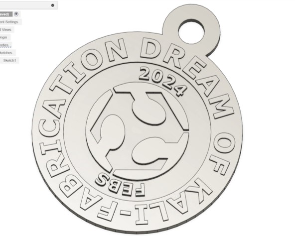
Design
We made a small design in Fusion 360 to compare different method to make a mold.

SLA Printing
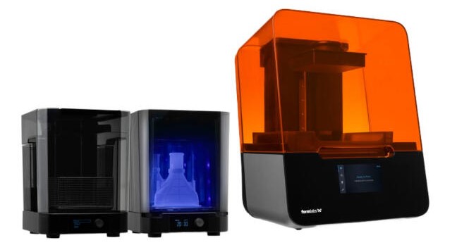
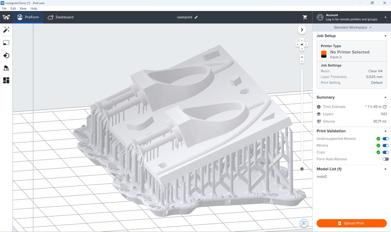
At the lab, we have a few resin printers, but the one I'll be using is the Form 3+ SLA printer by Formlabs. The slicer I used for this was Preform, and the settings I used were:
- Layer height: 0.025mm
- Resin: Clear v4
- Print settings: default
- Estumated print time: 7h 45min
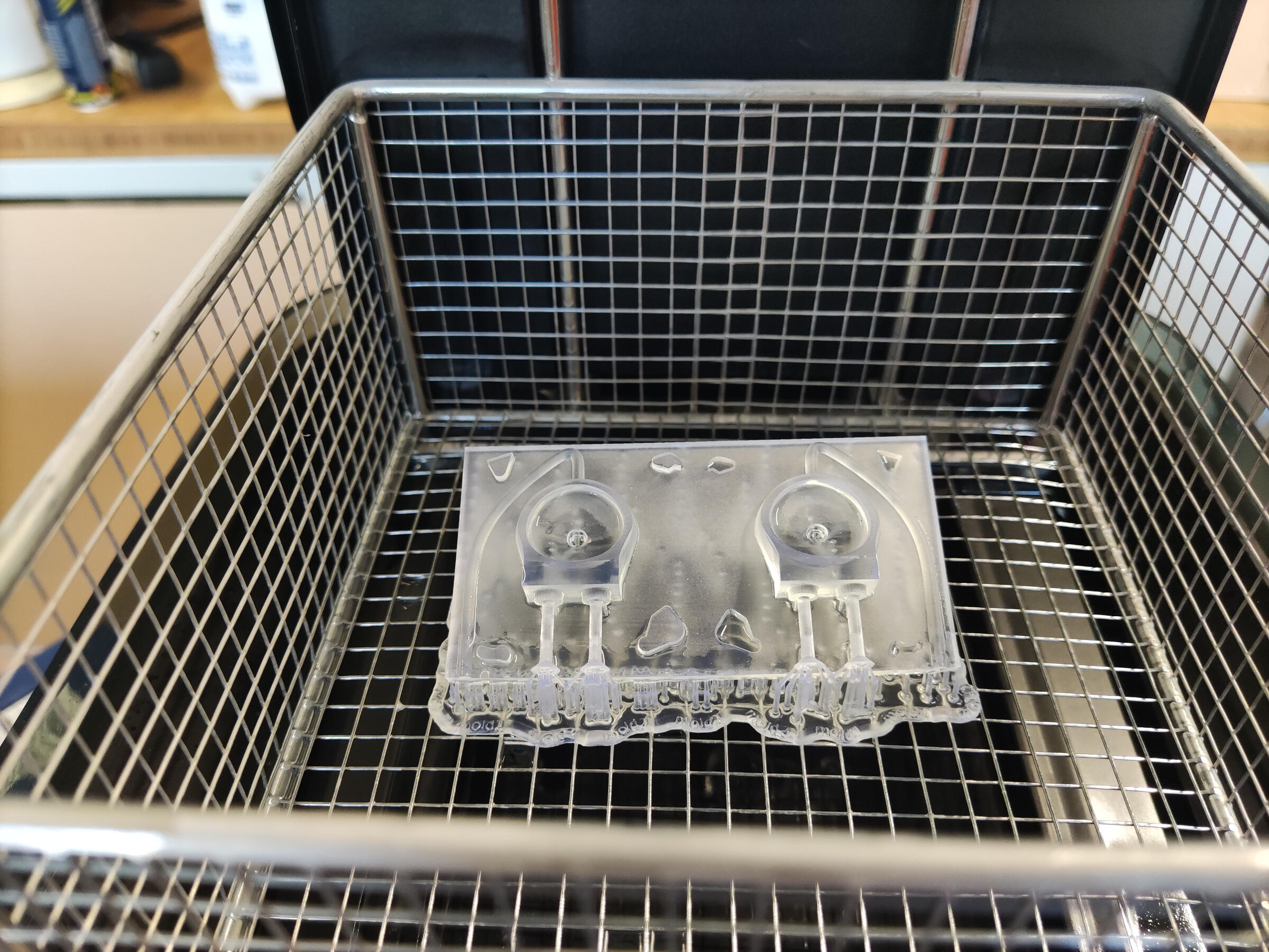
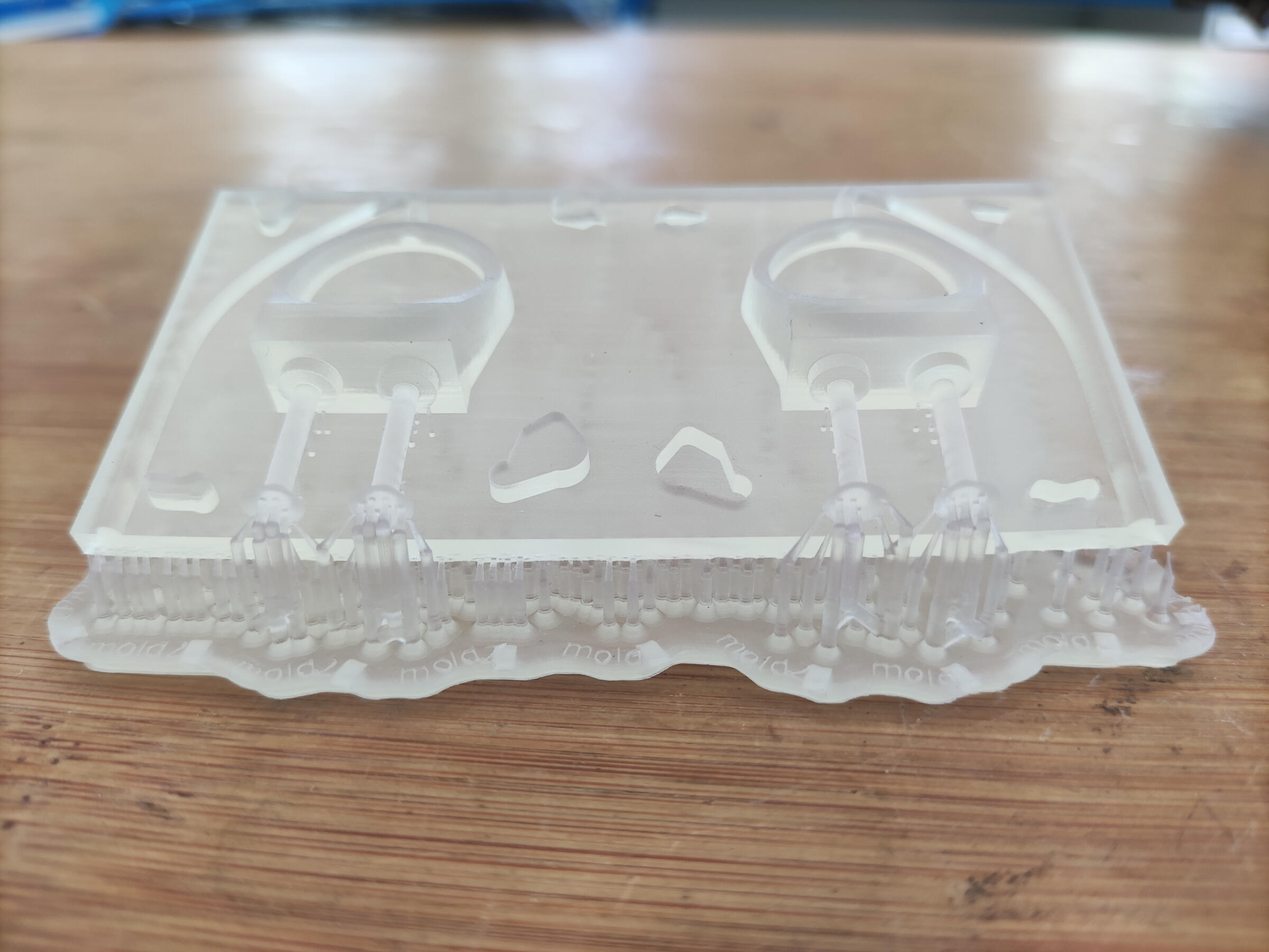
I left this print overnight, and the next morning it was ready. The final steps involved washing it in isopropyl alcohol and curing it under UV light. At the lab, we have both a UV curing chamber and a wash station, so it was quite easy to do this. Regarding the washing process, since the print is quite small, I left it in the washing station for about 30 minutes, and then cured it for an additional 30 minutes. Lastly, I removed the supports, and the print was ready to be used.
here is the final result, the difernce in the quality of the print is very noticeable, and this is crucial if you want to make a good mold for casting. where the layers won't be visible in the final product.
Milling
Pulse Width Modulation (PWM) is a technique where a power source is rapidly switched on and off at varying intervals. The width of the on-time pulses can be adjusted, allowing control over the average power delivered to a device. It's commonly used in applications like motor speed control and LED dimming for its efficient and precise power regulation capabilities.
    const int PWMpin = 2;


    void setup() {

        pinMode(PWMpin, OUTPUT);
    }

    void loop() {


            analogWrite(PWMpin, 200);

        }
When measuring the voltage of that pin the multimeter showed a value of 3.9 V. We then measured the voltage with the oscilloscope to see PWM of thr Pin.

Milling on the Roland MDX40

For milling we used the Roland MDX40 machine at FabLab Kamp-Lintfort. In addition we used wax to create our mold.
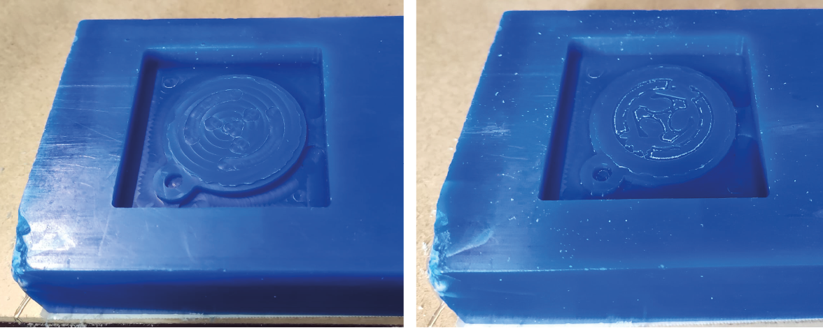
We used two different tools, 3mm and 1mm, to mill the wax. Even though we used the 1 mm tool to mill small details, it was not successful enough to mill the details of the small text in the design. As a result of milling, we see burrs on the wax and the details of the design are not clear.